 Adel Oubelaid
 Nabil Taib
 Toufik Rekioua
 Mohit Bajaj
 Arvind Yadav
 Mokhtar Shouran
 Salah Kamel
95% of researchers rate our articles as excellent or good
Learn more about the work of our research integrity team to safeguard the quality of each article we publish.
Find out more
ORIGINAL RESEARCH article
Front. Energy Res. , 15 September 2022
Sec. Smart Grids
Volume 10 - 2022 | https://doi.org/10.3389/fenrg.2022.971357
This article is part of the Research Topic Optimal Energy Management for Electric Vehicles (EVs) by the interface of Vehicle to Grid (V2G), Grid to Vehicle (G2V) and Smart Grid Scheduling View all 7 articles
High reliability is recommended in hybrid electric vehicle applications. In this study, a secure power management strategy has been developed for a fuel cell—supercapacitor hybrid electric vehicle. In addition to its ability to detect the occurrence of failures in vehicle power sources, the proposed power management strategy isolates the faulty source and reconfigures the control scheme to always guarantee bus voltage stability and vehicle traction even in faulty situations. The developed power management strategy enhances vehicle comfort and prevents exhausting one source over another by allowing the fuel cell and the supercapacitor to operate at different power levels. The multiloop control scheme associated with the power sources is highly reliable since both sources can run the vehicle alone and regulate the bus voltage. Vehicle speed and torque controllers are simultaneously tuned using a particle swarm optimization algorithm. Torque and speed ripples are automatically minimized via the use of a new proposed cost function. This approach made the controller design easier and gave the designer the possibility to tradeoff between the variables to be minimized.
In the last decade, several studies were carried out to investigate alternative nonpolluting energy sources to solve the persisting problem of carbon emission. Vehicle electrification was among the proposed solutions for the elimination or at least the reduction of gas emission. This solution has attracted many researchers and different research axes have been born out of the increasing interest given to this idea, such as vehicle safety and security (Sabaliauskaite et al., 2019), energy management (Zhang et al., 2017a; Yadav and Maurya, 2021a; Yadav and Maurya, 2021b; Yadav and Maurya, 2022), power sources protections (Oubelaid et al., 2022a), power train architecture (Wu et al., 2015), intelligent transportation (Oubelaid et al., 2022b; Oubelaid et al., 2022c), and vehicle control (Max and Lantos, 2014; Vajsz et al., 2017; Oubelaid et al., 2022d).
Hybrid electric vehicles can be thought of as mobile embedded systems that are subjected to unpredictable driving conditions. Knowing that environmental driving conditions are harsh and random, hybrid electric vehicles are permanently subjected to failure risk, which may be due to a fault in one of their components. Several research studies discussing the enhancement of hybrid electric vehicle security are available in the literature. To ensure continuous vehicle operation, researchers use different fault tolerant strategies which are applied to different hybrid electric vehicle components. Yu et al. (2017), Kersten et al. (2019), and Moosavi et al. (2019) have discussed possible open circuit faults occurring in inverters used in electrified vehicles. Faults taking place in traction machines and ensuring electric vehicle traction are also extensively studied in the literature. Mellor et al. (2003), Tashakori and Ektesabi (2013), Kaplan et al. (2021), Liu et al. (2021), and Wu et al. (2022) have proposed fault tolerant control strategies to handle possible faults in vehicle traction machine and ensure continuous and secure operation. Faults which may occur in the different sensors on vehicle boards are also extensively studied in the literature (Kommuri et al., 2016; Peñate et al., 2018; Yu et al., 2021; Zhang et al., 2021). To summarize, although inverters, traction machines, and sensors are more robust compared to fuel cells and supercapacitors, few research works have dealt with possible faults at the vehicle power sources level, except for some works which have mainly discussed power sources degradation (Shchurov et al., 2021; Song et al., 2021; Yi et al., 2022).
As mentioned earlier, vehicle power sources such as fuel cells are too sensitive. In addition, hybrid electric vehicles are always subjected to fast and abrupt load variations which could result in significant damage at both the source and motor sides. For the aforementioned reason, scientists have increased their efforts in developing novel control techniques which protect sensitive power sources such as fuel cells from possible damage due to sudden load variations. Ou et al. (2017) proposed a novel control technique that protects FC from overheating and air starvation that may be caused by rapid load variation. Koprivsek (2018) developed an over-current protection strategy to protect the battery electric vehicles from high currents resulting from rapid load variations. Liu et al. (2017) and Zhang et al. (2020) presented filter based control technique to protect both fuel cells and batteries from transient current ripples arising during abrupt power reference variation caused by abrupt load variations using rate limiters and a first-order transfer function to restrict fuel cell and battery output power and to produce a time delay necessary for the electrochemical reactions that occur within the FC. To conclude, vehicle power sources are so sensitive, and their failure possibility has to be taken into account when elaborating on control techniques or power management strategies.
Recently developed power management strategies for hybrid electric vehicles take into account the sensitivity and slowness of some vehicle power sources, such as fuel cells, but do not consider their possible failure. Ou et al. (2019) proposed a novel energy management technique based on fuzzy logic and state machine control techniques to enhance FC lifespan. He et al. (2020), Tao et al. (2020), and Trinh and Ahn (2021) developed energy management strategies that take into account only FC slow dynamics but do not consider its possible failure, and this reduces driving security. In many research works (Thounthong et al., 2009; Hwang et al., 2012; Zhang et al., 2017b; Wieczorek and Lewandowski, 2017; Meyer et al., 2018; Xie et al., 2018; Zhang et al., 2018; Raghavaiah and Srinivasarao, 2019; Kakouche et al., 2022), one power source always performs DC bus regulation, and the second source intervenes either during regenerative braking or to help the primary source during accelerations and high power demands. In case of failure of the sources fixing the DC bus voltage, the vehicle will lose its main powering source, and this may lead to serious vehicle damages and even total vehicle failure.
In this study, a novel power management strategy that takes into account possible failures in vehicle power sources is presented in this work. Unlike the previously mentioned power sharing techniques, the proposed management strategy offers the following advantages:
• Precise power flow control since, at any driving instant, the fuel cell can deliver any desired fraction of the total power required for traction
• Power sources are operated at known and defined operating points, and this reduces the stress applied on them during high power demands and, hence, increases their lifespan.
• Secure vehicle operation: a fault detection algorithm will detect possible failures in vehicle power sources and correct them via control loop reconfiguration.
Hybrid electric vehicle traction is ensured using direct torque control–based space vector modulation. All vehicle regulators are concurrently tuned using a particle swarm optimization algorithm. This aforementioned intelligent technique permits simultaneous tuning through the use of newly proposed cost functions that allows the designer to tradeoff and prioritize between the design variables to be minimized.
The motion of the vehicle shown in Figure 1 is governed by the following equation:
where
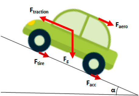
FIGURE 1. HEV in inclined surface.
The net resistive force is defined as given below:
where Faero is the aerodynamic force, Fg is the force due to gravity, Ftire is the friction force which exists between the vehicle’s tire and ground surface, and Facc is the acceleration force required by the vehicle to reach maximum speed from rest. Details about the mathematical modeling of each force are provided in the study by Shchurov et al. (2021). Vehicle parameters which are used in this study are shown in Table1.
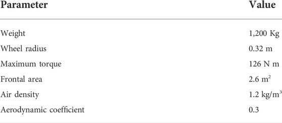
TABLE 1. HEV parameters.
The output voltage of one fuel cell (FC) is given by Eq. 3, which is approximately equal to 0.7 V. From this equation, one can notice the existence of several voltage drops, such as activation, ohm, and conduction voltage drops. More information about FC dynamics is given in the study by Song et al. (2021). From Eq. 4, the voltage of one FC stack is formed by serial grouping of Ns = 68, which makes the stack nominal voltage approximately 48 V.
The voltage-current characteristic and power-current characteristics of one fuel cell stack are highlighted in Figure 2. The green points on the curves represent the nominal current, voltage, and power of the used FC.
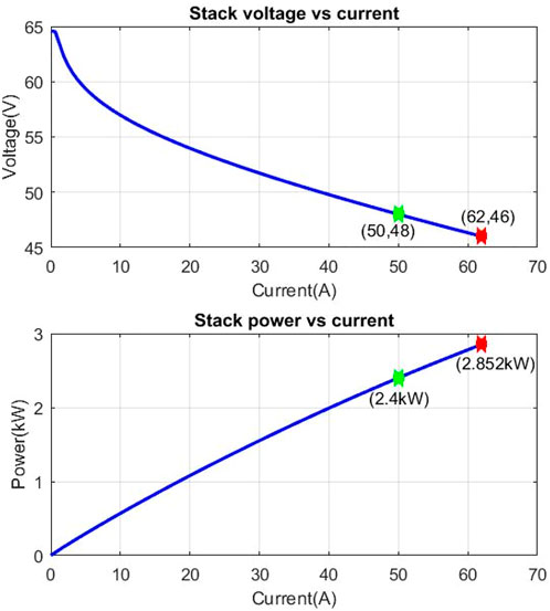
FIGURE 2. Fuel cell characteristic curves.
The supercapacitor (SC) is used along with the fuel cell to make up for the FC’s slow dynamics and also to increase vehicle performance. In addition to their fast dynamics, SCs are known for their robustness and their high number of charge and discharge cycles. Figure 3 shows the SC characteristic curve where one can notice that it gets charged very fast and sustains very high charge currents.
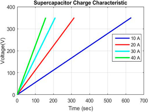
FIGURE 3. Supercapacitor characteristic curve.
The electrical SC equivalent circuit is shown in Figure 4. It is modeled as a controlled voltage source in series with an equivalent series resistance, as shown next.
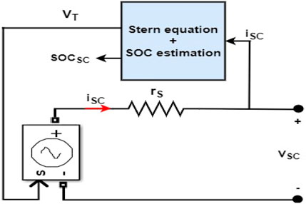
FIGURE 4. Electrical supercapacitor equivalent model.
SC cell voltage VSC is calculated by Eq. 5 using the Stern equation. Details about this last-mentioned equation are provided in the study by Yi et al. (2022). The SC state of charge (SOCSC) is calculated by Eq. 6 using the initial and the total SC charges, Qinit and QT, respectively.
The total SC stack voltage is given by Eq. 7:
where Vsc, tot is the total SC voltage, Vsc is the SC cell voltage, and Nsc is number of series supercapacitors.
Permanent magnet synchronous machine (PMSM) is used to ensure HEV traction. It is chosen among other types of machines because of its robustness and its high torque to mass ratio, which means that it can deliver high torque and occupy small place in the space at the same time.
Stator flux and currents of PMSM motor in the dq rotating frame are, respectively, given by Eq. 8 and Eq. 9:
where rS and L are the stator resistance and inductance, respectively.
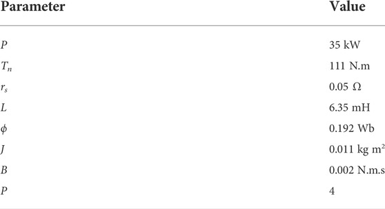
TABLE 2. HEV and environment parameters.
The HEV discussed in this study is shown in Figure 5. It can be seen that the traction machine is controlled using direct torque control–based space vector modulation This control technique was chosen on purpose because of the fast torque response it provides.
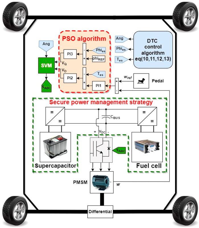
FIGURE 5. Top view of SC-FC HEV.
At each sampling time Ts, the flux on the αβ frame and flux magnitude are estimated using Eq. 10 and Eq. 11. It is worth noticing that the PMSM stator resistance was neglected during flux estimation. Eq. 12 and Eq. 13 are used to estimate PMSM torque and rotor angle, respectively.
Figure 6 presents the steps followed for the integration of particle swarm optimization (PSO) along with the DTC control technique. PSO is used offline to provide a self-tuning for HEV regulators: PI1, PI2, and PI3.
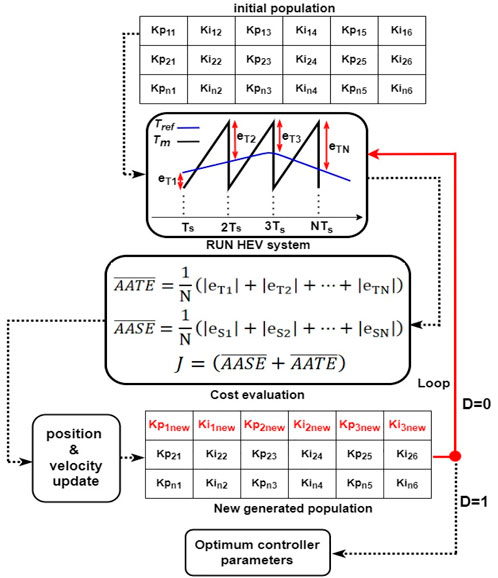
FIGURE 6. Integration of PSO to the HEV control system.
The steps for the integration of this optimization technique into the HEV control system are as follows:
• Initialize the swarm in a six-dimension search space.
• For each population particle, run the HEV system for a complete speed profile and evaluate the particle’s performance using the following cost function:
• Apply penalty function to exclude unstable PI combinations that result in infinite cost values. Infinite or large cost values mean that the actual PMSM speed or torque values are too far from their references.
• Update the particle’s speed and position using Eq. 18 and Eq. 19, respectively
• Evaluate the cost of the particle at its new location. If it is smaller than the previous cost value, then update it
• Keep iterating until the decision signal D (Figure 6) is 1. This last-mentioned signal is equal to 1 when the maximum number of iterations is elapsed or the minimum cost is reached.
• Extract the best position resulting in the smallest cost value.
The used PSO parameters in this study are highlighted in Table 3.
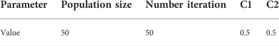
TABLE 3. Particle swarm optimization parameters.
The connection of the SC and FC to the inverter DC bus is made, respectively, through bidirectional and unidirectional DC/DC converters, as shown in Figure 7.
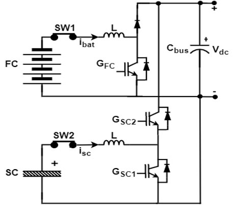
FIGURE 7. Connection of power sources to DC bus.
As mentioned earlier, SC and FC have complementary characteristics. This is why their use has to be managed to ensure driving comfort and good vehicle performance. Figure 8 highlights a top-level view of the proposed fault-tolerant power management strategy developed in this study. This bloc takes as inputs the power required by the HEV PHEV, supercapacitor current iSC and its SOC and FC current. It outputs three gate signals that control the operation of the power sources through the control of DC/DC converters gate signals.
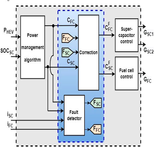
FIGURE 8. Proposed secure power management strategy.
The blue highlighted area in Figure 8 is used for the detection of faults that may occur in HEV power sources. If the SC or FC is in a failure state, this bloc will detect the fault and isolate it. After that, it will reconfigure the control loops associated with the power sources to ensure HEV traction and DC bus regulation. Details about this bloc are discussed in the coming sections. The signals NFC and NSC are called initial control signals, and A and B are considered final control signals.
In this work, the required HEV power is divided into three sets: low-power PL, average-power PA and high-power PH. The supercapacitor SOC is divided into four levels, as given by Eq. 20:
The power management algorithm sub bloc highlighted in Figure 8 takes as input the required HEV power and the supercapacitor SOC and outputs two initial control signals NFC and NSC which are integers ranging from 1 to 4. These two last mentioned signals will be used to control the flow of power in FC and SC during normal HEV operation (absence of failures in HEV power sources). The table below presents different rules that are used by the power the management algorithm unit shown in Figure 8.
From the Table 4 the following subsections, one can notice that the proposed energy management not only switches ON and OFF the power sources but also controls the percentage of power delivered by each source, as shown in the following sub-sections:

TABLE 4. Different driving rules.
The flow of power in the FC is controlled using the control scheme shown in Figure 9. Four loops are connected to a multiport switch, whose output depends on the final control signal
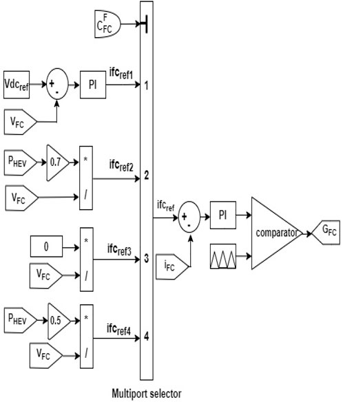
FIGURE 9. FC control scheme. If
If
If
If
The SC control scheme is shown in Figure 10. Multiple SC reference currents are connected to a multiport switch, whose output depends on the final control signal
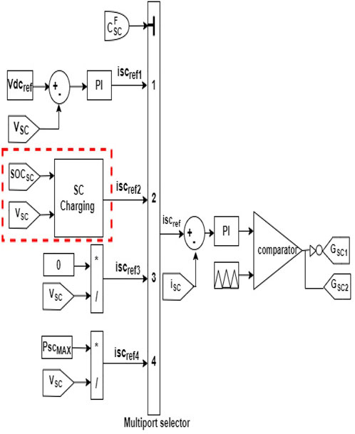
FIGURE 10. SC control scheme.
If
If
If
If
The dashed red lines of Figure 10 show the SC charging bloc, which takes as input the SC voltage and its SOC. Eq. 21 presents the two SC charging modes depending on the SOC. These two formulas limit the charging currents and prevent the SC from damage caused by current abrupt peaks.
While FC or SC is operating alone (mode 1, 2, 5, and 13), the initial control signal of the other nonoperating source (
The used function for the detection of any possible fault in the FC is given by the following equation:
In order to detect faults on SC, the following equation is used:
Once a fault is detected, the faulty source will be isolated, and the HEV must keep running by relying only on one source. When a fault occurs, the fault correction bloc, shown in Figure 8, uses the following truth table to reconfigure the control scheme and to isolate the faulty source. The correction bloc outputs two control signals
From the Table 4 the following subsections, it can be seen that, in the absence of faults (FSC = FFC = 0), the isolation bloc outputs directly the initial control signals generated by the management algorithm bloc and behaves as IN-OUT bloc. When a fault occurs, the final control signal of the non-faulty source (
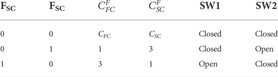
TABLE 5. Fault correction truth table.
To evaluate the effectiveness of the developed fault-tolerant power management algorithm, we cause, on purpose, two temporary faults, F1 and F2, and one permanent fault, F3, as listed below:
F1: Temporary fault occurs in FC at 84s and lasts 5s.
F2: Temporary fault occurs in SC at 300s and lasts 5s.
F3: Permanent fault occurs in FC and persists till the end of the ride.
Figure 11 shows the HEV speed along with the reference speed applied for the HEV during the 660s. It is clear that the HEV speed tracks well its reference. Figure 12 shows the HEV torque response. The vehicle torque matches its reference, and the torque ripples are minimized in a narrow hysteresis band.
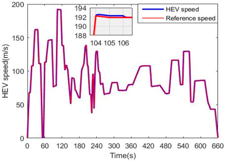
FIGURE 11. HEV speed response.
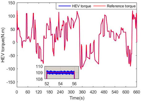
FIGURE 12. HEV torque response.
Initial control signals, final control signals, and fault signals generated are shown in Figure 13. One can notice that during normal operation, the final control signals A and B are the initial control signals image of NSC and NFC, respectively,
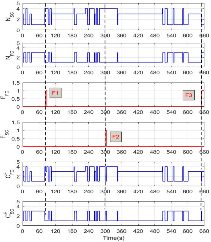
FIGURE 13. Fault and control signals during HEV ride.
generated by the power management algorithm. When a failure occurs in either SC or FC, the fault detection bloc detects the fault, and the isolation bloc uses the truth table in Table 5 to determine whether to isolate the faulty source and to keep the DC bus voltage at its reference.
• At F1: “
• At F2: “
• At F3: “
One can also remark on the effectiveness of the fault detection bloc, which did not emit any false threshold signal and responded immediately to the different faults.
Figure 14 shows the HEV, SC power, and FC power. It can be seen that the HEV power, at each instant, is obtained as the sum of SC and FC powers. It can be seen that during fault situations (F1, F2, and F3), the non-faulty source ensures HEV traction and the faulty source is isolated.
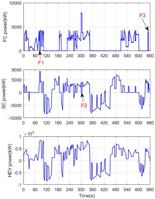
FIGURE 14. SC, FC, and HEV powers.
To provide a closer look at the behavior of power sources during vehicle ride, Figure 15 shows the SC and FC power along with the driving mode number during the period [75.5s and 92.5s].
• During [75.5, t1]: During this time period, SOCSC = SOCN and HEV power demand is low. Following Table 4, FC will ensure HEV traction while fixing DC bus voltage
• During [t1, t2]: In this time interval, HEV power demand is average, and SOCSC belongs to SOCN. In this case, both FC and SC will provide 50% of the total power required for traction, as shown in Figure 15, where both sources deliver half of the load power applied on the HEV
• During [t2, t3] U [t4, t5]: During this time period, HEV power demand is high, and the SC state of charge belongs to SOCN. Hence, FC and SC deliver 50% of the required traction power for traction, as highlighted in Figure 15, where both sources deliver 4 kW.
• During [t3, t4]: In this time interval, a fault occurs at the FC level, while HEV power demand is high and SOCSC belongs to SOCN. The fault detection and correction block, shown in Figure 8, overwrite the decision of the power management algorithm to ensure continuous HEV operation and DC bus regulation. This is achieved through the reconfiguration of the SC control scheme to position 1 (
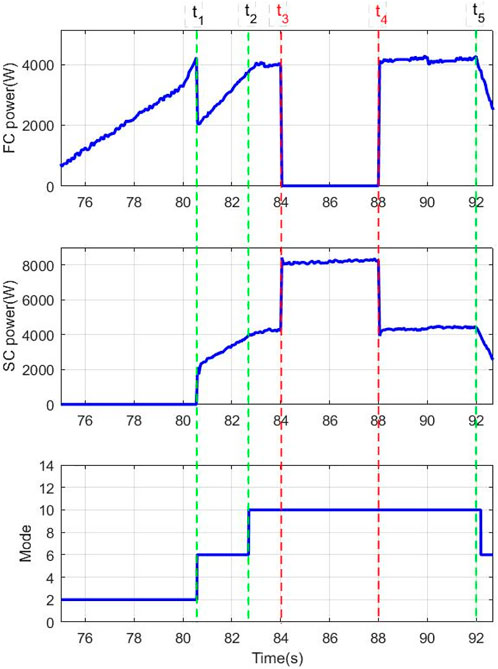
FIGURE 15. SC, FC, and HEV powers.
Figure 16 shows the SC SOC. It dropped from 82 to 70% during [210s, 350s], which corresponds to an average- and high-power demand. During the regenerative braking period [350,450], SOCSC increased from 70 to 86%. Globally, the SOCSC stayed within safe limits during the ride.
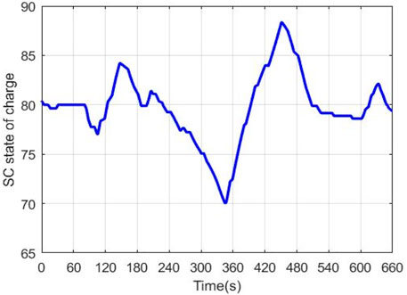
FIGURE 16. SC state of charge.
Figure 17 highlights the inverter DC bus voltage. One can notice that it follows its reference set to 560 V. The presence of some voltage ripples due to connection and disconnection of power sources can be remarked. These ripples are within an allowed band of 10 V. The zooms in Figure 17 present the voltage fluctuations during the occurrence of faults. These fluctuations are always within safe limits.
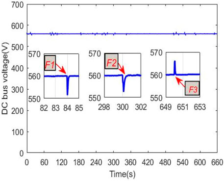
FIGURE 17. DC bus voltage.
The minimum cost after each iteration is shown at 18. It can be seen that cost decreases over iterations, which means that the solutions produced after each generation are better than the previous ones in term of torque and speed ripple minimization. Starting from 30, the cost value is constant, which means that the PSO algorithm converges to an optimum solution.
The effectiveness of the proposed energy management strategy is assessed by implementing it in real-time using the OPAL-RT LAB simulator. Figure 18 describes in detail how the HEV model is adapted for simulation on the aforementioned simulation platform. The first step toward RT simulation is model separation. It should be divided into computation and console blocks, which are highlighted with blue and dark dashed lines, respectively, in Figure 18. The console block contains user interface blocks such as scopes, displays, manual switches, and constants. It is worth noticing that the console block runs asynchronously only on the host PC from the computation subsystems. The computational subsystem contains all the computational elements of the model, mathematical operations, I/O blocks, signal generators, and physical models. Data between the computation subsystem and console are exchanged asynchronously through the TCP/IP link, but data exchange between two computation subsystems, namely, master (SM) and slave (SS), is performed synchronously through shared memory. Data from the RT simulator are displayed on the digital oscilloscope using Bayonet Neill–Concelman connector (BNC) to BNC cable.
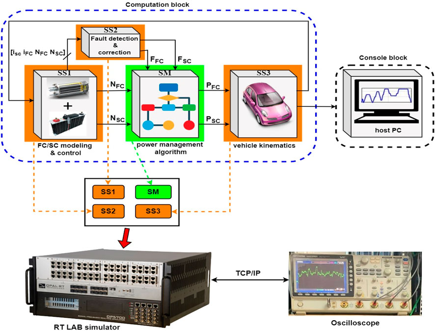
FIGURE 18. Real-time simulation using RT LAB.
After building and loading the HEV program to the OP 57000 simulator, constant power of 5 kW is applied as a load power to the vehicle. This requested power will be ensured by FC and SC following the proposed energy management strategy. Figure 19 shows the obtained results using the RT LAB simulator, where fuel cell and supercapacitor powers are highlighted with magenta and blue colors, respectively. The aforementioned figure confirms the facts stated in section 5 where it has been said that the fuel cell can be operated safely at different predefined operating points. In zone 1 (Z1), the supercapacitor delivers all the necessary power for traction while the fuel cell is turned off by setting its control loop to position 3, as shown in Figure 9. In zone 2 (Z2), FC and SC control loops were set to positions 4 and 1, respectively. This last-mentioned control loop configuration has made both FC and SC deliver 50% of the required power for traction. It is worth noticing that SC in Z2 delivers 50% of the required power for traction while ensuring DC bus regulation. At Z3, a temporary fault took place at the FC level. As soon as the fault occurs at the fuel cell level, as pointed out with white dashed lines, the fault detection and correction block, already shown in Figure 20, will intervene to isolate the FC and overwrite the power management algorithm by forcing FC power to zero. This is performed by the reconfiguration of the FC control loop from position 4 to position 3, as shown in Figure 9. This will make the supercapacitor deliver, alone, all the power required for traction while ensuring DC bus regulation. From zone 4 to 8, one can see that the fuel cell delivers a percentage of total power that is equal to the power contribution factor CFC. For example, in zones 4, 5, and 6, the fuel cell delivers respectively 50, 100, and 30% of the required power for traction. One of the advantages of such a power management technique is the precise control of power flow in power sources. In addition to that, this power management strategy reduces the stress applied on power sources by preventing their operation above their maximum power. In zone 9, a fault occurred at the SC level, which is responsible for DC bus regulation. The fault detection and correction block shown in Figure 20 has isolated SC by reconfiguring its control loop shown in Figure 9 from position 1 to position 3. Furthermore, the FC control loop was set to position 1 to ensure DC bus regulation and deliver all the necessary power for traction.
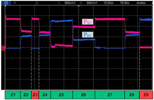
FIGURE 19. Real-time simulation using RT LAB.
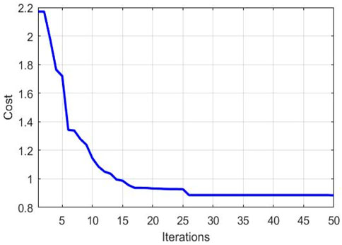
FIGURE 20. Evolution of cost over iterations.
The developed power management strategy has improved HEV security since failures in vehicle power sources are detected and isolated. HEV reliability and comfort are also enhanced because both SC and FC are able to regulate the DC bus voltage, power the HEV alone, and operate at different power levels. The offline use of PSO in the design of HEV controllers has made the controller design task easy and automatic via the use of a proposed cost function that trades between design variables to be minimized.
The original contributions presented in the study are included in the article/Supplementary Material; further inquiries can be directed to the corresponding author.
All authors listed have made a substantial, direct, and intellectual contribution to the work and approved it for publication.
The authors declare that the research was conducted in the absence of any commercial or financial relationships that could be construed as a potential conflict of interest.
All claims expressed in this article are solely those of the authors and do not necessarily represent those of their affiliated organizations, or those of the publisher, the editors, and the reviewers. Any product that may be evaluated in this article, or claim that may be made by its manufacturer, is not guaranteed or endorsed by the publisher.
He, H., Quan, S., Sun, F., and Wang, Y. X. (2020). Model predictive control with lifetime constraints based energy management strategy for proton exchange membrane fuel cell hybrid power systems. IEEE Trans. Ind. Electron. 67 (10), 9012–9023. doi:10.1109/TIE.2020.2977574
Hwang, J. J., Chen, Y. J., and Kuo, J. K. (2012). The study on the power management system in a fuel cell hybrid vehicle. Int. J. hydrogen energy 37 (5), 4476–4489. doi:10.1016/j.ijhydene.2011.11.127
Jnayah, S., and Khedher, A. (2019). “DTC of induction motor drives fed by two and three-level inverter: Modeling and simulation,” in 2019 19th international conference on sciences and techniques of automatic control and computer engineering (STA) (IEEE). doi:10.1109/STA.2019.8717227
Kakouche, K., Rekioua, T., Mezani, S., Oubelaid, A., Rekioua, D., Blazek, V., et al. (2022). Model predictive direct torque control and fuzzy logic energy management for multi power source electric vehicles. Sensors 22, 5669. doi:10.3390/s22155669
Kaplan, H., Tehrani, K., and Jamshidi, M. (2021). A fault diagnosis design based on deep learning approach for electric vehicle applications. Energies 14 (20), 6599. doi:10.3390/en14206599
Kersten, A., Oberdieck, K., Bubert, A., Neubert, M., Grunditz, E. A., Thiringer, T., et al. (2019). Fault detection and localization for limp home functionality of three-level NPC inverters with connected neutral point for electric vehicles. IEEE Trans. Transp. Electrific. 5 (2), 416–432. doi:10.1109/tte.2019.2899722
Kommuri, S. K., Defoort, M., Karimi, H. R., and Veluvolu, K. C. (2016). A robust observer-based sensor fault-tolerant control for PMSM in electric vehicles. IEEE Trans. Ind. Electron. 63 (12), 7671–7681. doi:10.1109/tie.2016.2590993
Koprivsek, M. (2018). “Advanced solutions in over-current protection of hvdc circuit of battery-powered electric vehicle,” in PCIM europe 2018; international exhibition and conference for power electronics, intelligent motion (Nuremberg, Germany: Renewable Energy and Energy ManagementVDE), 1–4.
Liu, J., Li, H., and Deng, Y. (2017). Torque ripple minimization of PMSM based on robust ILC via adaptive sliding mode control. IEEE Trans. Power Electron. 33 (4), 3655–3671. doi:10.1109/TPEL.2017.2711098
Liu, X., Yu, F., Mao, J., and Yang, H. (2021). Pre-and post-fault operations of six-phase electric-drive-reconstructed onboard charger for electric vehicles. IEEE Trans. Transp. Electrific. 8 (2), 1981–1993. doi:10.1109/tte.2021.3113316
Max, G., and Lantos, B. (2014). Time optimal control of four-in-wheel-motors driven electric cars. Period. Polytech. elec. Eng. Comp. Sci. 58 (4), 149–159. doi:10.3311/PPee.7806
Mellor, P. H., Allen, T. J., Ong, R., and Rahma, Z. (2003). Faulted behaviour of permanent magnet electric vehicle traction drives. IEEE Int. Electr. Mach. Drives Conf. 1, 554–558.
Meyer, R. T., Johnson, S. C., DeCarlo, R. A., Pekarek, S., and Sudhoff, S. D. (2018). Hybrid electric vehicle fault tolerant control. J. Dyn. Syst. Meas. Control 140 (2). doi:10.1115/1.4037270
Moosavi, S. S., Kazemi, A., and Akbari, H. (2019). A comparison of various open-circuit fault detection methods in the IGBT-based DC/AC inverter used in electric vehicle. Eng. Fail. Anal. 96, 223–235. doi:10.1016/j.engfailanal.2018.09.020
Ou, K., Wang, Y. X., and Kim, Y. B., (2017). Performance optimization for open‐cathode fuel cell systems with overheating protection and air starvation prevention. Fuel Cells 17, 299. doi:10.1002/fuce.201600181
Ou, K., Yuan, W. W., Choi, M., Kim, J., and Kim, Y. B. (2019). Development of new energy management strategy for a household fuel cell/battery hybrid system. Int. J. Energy Res. 43 (9), 4686–4700. doi:10.1002/er.4606
Oubelaid, A., Albalawi, F., Rekioua, T., Ghoneim, S. S., Taib, N., and Abdelwahab, S. A. M. (2022). Intelligent torque allocation based coordinated switching strategy for comfort enhancement of hybrid electric vehicles. IEEE Access 10, 58097–58115. doi:10.1109/ACCESS.2022.3178956
Oubelaid, A., Alharbi, H., B Humayd, A. S., Taib, N., Rekioua, T., and Ghoneim, S. S. M. (2022). Fuzzy-energy-management-based intelligent direct torque control for a battery—supercapacitor electric vehicle. Sustainability 14, 8407. doi:10.3390/su14148407
Oubelaid, A., Taib, N., Nikolovski, S., Alharbi, T. E. A., Rekioua, T., Flah, A., et al. (2022). Intelligent speed control and performance investigation of a vector controlled electric vehicle considering driving cycles. Electronics 11 (13), 1925. doi:10.3390/electronics11131925
Oubelaid, A., Taib, N., and Rekioua, T. (2022). “Novel coordinated power sources switching strategy for transient performance enhancement of hybrid electric vehicles,” in COMPEL-The international journal for computation and mathematics in electrical and electronic engineering. doi:10.1108/COMPEL-10-2021-0399
Peñate, S. G., Estrada, F. R. L., Palomo, G. V., Ríos, R. O., Hernández, J. A. Z., Rojas, C. R., et al. (2018). Sensor fault diagnosis observer for an electric vehicle modeled as a Takagi-Sugeno system. J. Sensors, 1–9. doi:10.1155/2018/3291639
Raghavaiah, K., and Srinivasarao, G., (2019), Design and simulation of a controller for a hybrid energy storage system based electric vehicle, Math. Model. Eng. Problems, 6 (2), 203–216. doi:10.18280/mmep.060208
Sabaliauskaite, G., Liew, L. S., and Zhou, F. (2019). “AVES–Automated vehicle safety and security analysis framework,” in ACM computer science in cars symposium, 1–8. doi:10.1145/3359999.3360494
Shchurov, N. I., Dedov, S. I., Malozyomov, B. V., Shtang, A. A., Martyushev, N. V., Klyuev, R. V., et al. (2021). Degradation of lithium-ion batteries in an electric transport complex. Energies 14 (23), 8072. doi:10.3390/en14238072
Song, K., Ding, Y., Hu, X., Xu, H., Wang, Y., and Cao, J. (2021). Degradation adaptive energy management strategy using fuel cell state-of-health for fuel economy improvement of hybrid electric vehicle. Appl. Energy 285, 116413. doi:10.1016/j.apenergy.2020.116413
Tao, F., Zhu, L., Fu, Z., Si, P., and Sun, L. (2020). Frequency decoupling-based energy management strategy for fuel cell/battery/ultracapacitor hybrid vehicle using fuzzy control method. IEEE Access 8, 166491–166502. doi:10.1109/ACCESS.2020.3023470
Tashakori, A., and Ektesabi, M. (2013). Fault diagnosis of in-wheel BLDC motor drive for electric vehicle application. 2013 IEEE Intell. Veh. Symp. IV, 925–930.
Thounthong, P., Rael, S., and Davat, B. (2009). Analysis of supercapacitor as second source based on fuel cell power generation. IEEE Trans. Energy Convers. 24 (1), 247–255. doi:10.1109/TEC.2008.2003216
Trinh, H. A., and Ahn, K. K. (2021). “Energy management strategy for fuel cell hybrid power system using fuzzy logic and frequency decoupling methods,” in 2021 24th international conference on mechatronics technology (Singapore: ICMT), 1–6. IEEE. doi:10.1109/ICMT53429.2021.9687291
Vajsz, T., Számel, L., and Rácz, G. (2017). A novel modified DTC-SVM method with better overload-capability for permanent magnet synchronous motor servo drives. Period. Polytech. elec. Eng. Comp. Sci. 61 (3), 253–263. doi:10.3311/PPee.10428
Wieczorek, M., and Lewandowski, M. (2017). A mathematical representation of an energy management strategy for hybrid energy storage system in electric vehicle and real time optimization using a genetic algorithm. Appl. energy 192, 222–233. doi:10.1016/j.apenergy.2017.02.022
Wu, C., Sehab, R., Akrad, A., and Morel, C. (2022). Fault diagnosis methods and Fault tolerant control strategies for the electric vehicle powertrains. Energies 15 (13), 4840. doi:10.3390/en15134840
Wu, G., Zhang, X., and Dong, Z. (2015). Powertrain architectures of electrified vehicles: Review, classification and comparison. J. Frankl. Inst. 352 (2), 425–448. doi:10.1016/j.jfranklin.2014.04.018
Xie, S., Hu, X., Qi, S., and Lang, K. (2018). An artificial neural network-enhanced energy management strategy for plug-in hybrid electric vehicles. Energy 163, 837–848. doi:10.1016/j.energy.2018.08.139
Yadav, K., and Maurya, S. (2022). “A comparative study on the performance of energy storage systems for hybrid electric vehicles,” in Advances in energy technology (Singapore: Springer), 795–803.
Yadav, K., and Maurya, S. (2021). “Fuzzy control implementation for energy management in hybrid electric vehicle,” in 2021 international conference on computer communication and informatics (ICCCI) (IEEE), 1–5.
Yadav, K., and Maurya, S. K. (2021). “Modelling and control of power flow from auxiliary source in hybrid electric vehicle,” in Recent advances in power electronics and drives (Singapore: Springer), 217–227.
Yi, F., Lu, D., Wang, X., Pan, C., Tao, Y., Zhou, J., et al. (2022). Energy management strategy for hybrid energy storage electric vehicles based on pontryagin’s minimum principle considering battery degradation. Sustainability 14 (3), 1214. doi:10.3390/su14031214
Yu, L., Zhang, Y., Huang, W., and Teffah, K. (2017). A fast-acting diagnostic algorithm of insulated gate bipolar transistor open circuit faults for power inverters in electric vehicles. Energies 10 (4), 552. doi:10.3390/en10040552
Yu, Q., Wan, C., Li, J., Xiong, R., and Chen, Z. (2021). A model-based sensor fault diagnosis scheme for batteries in electric vehicles. Energies 14 (4), 829. doi:10.3390/en14040829
Zhang, D., Liu, G., Zhou, H., and Zhao, W. (2018). Adaptive sliding mode fault-tolerant coordination control for four-wheel independently driven electric vehicles. IEEE Trans. Ind. Electron. 65 (11), 9090–9100. doi:10.1109/TIE.2018.2798571
Zhang, L., Fan, Y., Cui, R., Lorenz, R. D., and Cheng, M. (2017). Fault-tolerant direct torque control of five-phase FTFSCW-IPM motor based on analogous three-phase SVPWM for electric vehicle applications. IEEE Trans. Veh. Technol. 67 (2), 910–919. doi:10.1109/TVT.2017.2760980
Zhang, L., Wang, Z., Ding, X., Li, S., and Wang, Z. (2021). Fault-tolerant control for intelligent electrified vehicles against front wheel steering angle sensor faults during trajectory tracking. IEEE Access 9, 65174–65186. doi:10.1109/access.2021.3075325
Zhang, S., Xiong, R., and Sun, F. (2017). Model predictive control for power management in a plug-in hybrid electric vehicle with a hybrid energy storage system. Appl. Energy 185, 1654–1662. doi:10.1016/j.apenergy.2015.12.035
Zhang, Z., Guan, C., and Liu, Z. (2020). Real-time optimization energy management strategy for fuel cell hybrid ships considering power sources degradation. IEEE Access 8, 87046–87059. doi:10.1109/ACCESS.2020.2991519
Ang Angle
DC Direct current
D Decision signal
DTC Direct torque control
FC Fuel cell
HEV Hybrid electric vehicle
PMSM Permanent magnet synchronous machine
PSO Particle swarm optimization
RT Real-time
SC Supercapacitor
SVM Space vector modulation
SABC Inverter gate signals
a Vehicle acceleration [m/s2]
Enernst Nernst voltage [V]
Ftraction External force [N]
Fr Resistive force [N]
Faero Aerodynamic force [N]
Fg Gravitational force [N]
Ftire Tire force [N]
Facc Acceleration force [N]
iSC Supercapacitor current [A]
m Vehicle mass [kg]
id Direct axis current [A]
iq Quadratic axis current [A]
L Stator inductance [H]
Ns Number of series fuel cells
Nsc Number of series supercapacitors
PFC Fuel cell power [kW]
Qinit Initial supercapacitor charge [C]
QT Total supercapacitor charge [C]
PSC Supercapacitor power [kW]
rsc Supercapacitor series resistance [Ω]
SOCSC Supercapacitor state of charge
VFC, cell Fuel cell voltage [V]
VFC Fuel cell stack voltage [V]
Vact Activation voltage drop [V]
Vohm Ohmic voltage drop [V]
Vcond Conduction voltage drop [V]
VSC Supercapacitor voltage [V]
VSC,tot Supercapacitor total voltage [V]
VT Terminal voltage [V]
Vd Direct axis voltage [V]
Vq Quadratic axis voltage [V]
P Motor power [kW]
Tn Motor nominal torque [N]
rs Motor stator resistance [Ω]
J Rotor inertia [kg.m2]
B Rotor viscous friction [N.m.s]
TS Sampling time [s]
VDC DC bus voltage [V]
Cbus Bus capacitor [F]
Ωi Reference speed at ith iteration [rad/s]
Ti Reference torque at ith iteration [N.m]
N Torque and speed vectors length
Keywords: hybrid electric vehicle, secure power management, particle swarm optimization, fuel cell, supercapacitor
Citation: Oubelaid A, Taib N, Rekioua T, Bajaj M, Yadav A, Shouran M and Kamel S (2022) Secure power management strategy for direct torque controlled fuel cell/ supercapacitor electric vehicles. Front. Energy Res. 10:971357. doi: 10.3389/fenrg.2022.971357
Received: 17 June 2022; Accepted: 19 August 2022;
Published: 15 September 2022.
Edited by:
Chi-Man Vong, University of Macau, ChinaReviewed by:
Jichao Hong, University of Science and Technology Beijing, ChinaCopyright © 2022 Oubelaid, Taib, Rekioua, Bajaj, Yadav, Shouran and Kamel. This is an open-access article distributed under the terms of the Creative Commons Attribution License (CC BY). The use, distribution or reproduction in other forums is permitted, provided the original author(s) and the copyright owner(s) are credited and that the original publication in this journal is cited, in accordance with accepted academic practice. No use, distribution or reproduction is permitted which does not comply with these terms.
*Correspondence: Mokhtar Shouran, c2hvdXJhbm1hQGNhcmRpZmYuYWMudWs=
Disclaimer: All claims expressed in this article are solely those of the authors and do not necessarily represent those of their affiliated organizations, or those of the publisher, the editors and the reviewers. Any product that may be evaluated in this article or claim that may be made by its manufacturer is not guaranteed or endorsed by the publisher.
Research integrity at Frontiers
Learn more about the work of our research integrity team to safeguard the quality of each article we publish.