
95% of researchers rate our articles as excellent or good
Learn more about the work of our research integrity team to safeguard the quality of each article we publish.
Find out more
ORIGINAL RESEARCH article
Front. Energy Res. , 22 August 2022
Sec. Electrochemical Energy Storage
Volume 10 - 2022 | https://doi.org/10.3389/fenrg.2022.967756
This article is part of the Research Topic Advanced Materials for Next-Generation Alkali-Ion Batteries View all 4 articles
 Yongquan Zhang1,2
 Baoshan Zhu1
 Qingguo Chi1*Hongchang Gao1Changhai Zhang1
 Tiandong Zhang1
 Kai Zhu2Dianxue Cao2
The transport performance of lithium ions affects the rate performance of the cathode at different current densities. The poor interface contact between a solid electrolyte and the cathode makes it difficult to transport lithium ions. Adding a solid electrolyte into the cathode material can improve lithium ion transport. In this paper, we prepared some cathodes with different doping ratios, including two common cathode materials (LiFePO4 and NCM811), and tested their rate and long cycle performance. LFP-10 has a specific discharge capacity of 79.75 mAh g−1 at 5C, and the Li+ diffusion coefficient of LFP-10 is 4.91 × 10⁻¹³ cm−2 s−1, which is about 13.4 times higher than the pure LiFePO4 sample. The rate performance of an all-solid-state battery has also been improved, and there is still more than 100 mAh g−1 capacity reserved at 60°C and 2C current density. This shows that the introduction of a PEGDA-based solid electrolyte can significantly improve the Li+ transport of the cathode, and the composite cathode also provides support for the future application of all-solid-state batteries.
Energy is the driving force for the continuous advancement of modern society. Traditional lithium-ion batteries with liquid electrolytes have been deeply studied as an excellent energy storage device (Kulova, 2020; Manthiram, 2020; Chen et al., 2021; Edge et al., 2021; Wang et al., 2021). However, lithium-ion batteries using organic electrolytes have two intractable shortcomings: most electrolytes use flammable organic electrolytes, which has great potential safety hazards (Liu K. et al., 2018; Ould Ely et al., 2019; Liu et al., 2020). Secondly, current lithium-ion batteries have low energy density, which makes it difficult to meet increasing needs, such as electric vehicles (Martins et al., 2021). Solid electrolyte solutions are expected to fundamentally solve these two problems (Mahmood, 2015; Chen et al., 2018a; Gonzalez Puente et al., 2021; Rajagopal et al., 2021). A solid electrolyte usually has high thermal stability; the high temperature resistance means a low risk of thermal runaway. Then, the structure of a solid-state electrolyte battery is lighter than a traditional battery. The solid electrolyte can both transport Li+ and separate the anode and cathode. These features will reduce the volume of a single battery, which is expected to improve the energy density of lithium-ion batteries and alleviate the “range anxiety” problem faced by owners of battery-powered vehicles.
Though the potential commercialization of solid-state electrolytes is amazing, there are still some key problems to be solved. Compared with a liquid electrolyte, the ionic conductivity of a solid electrolyte at room temperature is poor, which limits the rate performance of the battery. In particular, the polymer electrolyte crystallizes easily at room temperature, resulting in fewer free chain segments in the amorphous region used for Li+ migration, leading to a low ionic conductivity (10−6–10−7 S cm−1 at room temperature) (Liu et al., 2017; Chen et al., 2018b; Wu H. et al., 2020; Ding et al., 2021). Adding plasticizers such as succinonitrile (SCN) will effectively improve the ionic conductivity of polymer electrolytes, but this practice will reduce their mechanical properties (Xin et al., 2021). The decline of mechanical properties will lead to poor interface contact between electrode and electrolyte. Simultaneously, the solid electrolyte cannot spontaneously penetrate into the electrode. This “solid-solid interface contact” will lead to extremely high interface resistance, and the increase of the internal resistance of the battery will undoubtedly cause greater difficulties for the transmission of Li+ and intensify polarization, thus affecting the performance of the battery (Shiraki et al., 2018; Dong et al., 2021).
In the past few years, many targeted methods have been proposed. For example, Chen designed an electrolyte membrane structure with cathode support; a layer of electrolyte slurry is cast on the surface of the cathode. The capacity performance of each discharge rate at 50°C is significantly improved compared with the traditional method, and the average discharge-specific capacity at 1C is 110 mAh g−1 (Chen et al., 2019). Similarly, Yun pressed a sulfide electrolyte and electrodes together in a specific container by means of hot-pressing polymerization. While enhancing the interface contact effect, it also effectively inhibits the occurrence of side reactions. The battery has not incurred significant capacity degradation after 50 cycles at a current density of 18 mAh/g (Yun et al., 2022). However, these methods often have high craftsmanship requirements, and the estimation of the quality of electrode materials is not accurate enough. Another method is to mix the solid electrolyte into a cathode to gain a composite cathode. Zhang et al. mixed 10% sodium-based electrolyte into the Na0.44MnO2 cathode and obtained a full battery that can stably cycle 160 times (Zhang et al., 2021). Wu’s team also added 10% polyethylene oxide (PEO) and LiTFSI into LiFePO4, resulting in a stable battery voltage platform and small polarization (Wu N. et al., 2020). Yu mixed a PEGDA-based composite electrolyte component into NCM811 electrode material at a ratio of 25%, and the battery has an average discharge-specific capacity of 69.5 mAh g−1 at 1C at room temperature (Yu et al., 2021).
The second method is an effective way to improve the performance of a battery, but the specific impact mechanism needs to be studied. In this work, we used PEGDA-based Ses to prepare composite cathodes with different doping ratios to explore the regulation mechanism of this modification of Li+ transport. We found that the incorporation of solid-state components is both effective for all-solid-state batteries and has a significant impact on the performance of the cathode itself, especially at high current density. We found the best performance for all-solid-state lithium batteries using LFP-10. It has a discharge-specific capacity of more than 100 mAh g−1 at 2C and 60°C, while the unmodified sample has a very low capacity. This reflects that the lithium-ion transport capacity of the modified cathode has been greatly improved, which has a good application prospect.
Polyethylene glycol diacrylate (PEGDA, Aladdin, MW = 600), polyethylene oxide (PEO, Aladdin, MW = 600,000), LiFePO4 (Tianchenghe, Shenzhen), NCM811 (Tianchenghe, Shenzhen), Super P (Kejinng, Hefei), PVDF (Solvay), N-methylpyrrolidone (NMP, Aladdin), lithium bis(trifluoromethane sulfonimide) (LiTFSI, Aladdin), anhydrous acetonitrile (Aladdin), succinonitrile (SCN, Macklin).
PEGDA and PEO were dissolved in anhydrous acetonitrile at the mass ratio of 1:5. LiTFSI (EO/Li = 12) was added at the same time, then plasticizer succinonitrile (SCN) and inorganic ceramic Li1.25Al0.25Zr1.75(PO4)3 (LAZP) were added in a certain proportion, and finally, a photoinitiator was added. The mass of the initiator accounted for 2% of the total mass of the polymers. After the electrolyte precursor solution completely dissolved, it was placed in a vacuum oven for 2 h to remove bubbles in the solution. The electrolyte slurry was evenly coated on the release film and transferred to a vacuum oven for 12 h at 50°C. The film was irradiated under an ultraviolet lamp for 30 min to obtain the final solid electrolyte membrane (SE).
PEGDA and LiTFSI were dissolved in NMP at a mass ratio of 7:3, and the solute in the solution was recorded as P-L. The cathode powder, PVDF, super P and P-L were dissolved in NMP according to different mass ratios, stirred for 6 h to obtain a uniform ink-like electrode mixed slurry, then coated on aluminum foil and dried at 80°C in a vacuum oven to obtain the required cathode sheet. The active substance mass of the electrode sheet was about 2.5–3 mg. All relevant system structures are shown in Figure 1.
Naming conventions: when the cathode material used is LFP, and the content of P-L added is 10%, it is named LFP-10, and so on. LFP-0, LFP-5 and LFP-15 are distinguished by the content of electrolyte, and the electrode sheet using NCM materials also adopts a similar naming method (NCM-x).
The composition of PEGDA in the cathode was characterized by FTIR. A small amount of cathode mixed slurry was placed in a vacuum oven at 80°C overnight. The corresponding powder and potassium bromide were pressed into a sheet in a solid state to test its IR spectrum; an X-ray diffraction instrument was used to characterize the crystal structure of the positive electrode. A Cu Κα radiation test was performed under the following conditions: the tube current was 40 mA, the tube voltage was 40 kV, the scanning range was 10–90°, the step size was 0.2°, and the residence time of each step was 0.75 s. A scanning electron microscope was used to analyze the surface morphology of active electrode material particles and prepared cathodes.
The charging and discharging performance were tested by a LANDIAN battery tester. The battery voltage test range using the LiFePO4 cathode was 3–4 V; when the cathode is NCM811, the voltage became 3–4.3 V.
The current density of the variable magnification performance test was conducted according to the magnification range of 0.2–10C (LiFePO4, 1C = 170 mAh g−1; NCM811, 1C = 270 mAh g−1). CV and EIS were tested by a CHI660E electrochemical workstation to explore the mechanism of PEGDA-based solid electrolyte improving the Li+ transport performance of the cathode. CV curves were tested with different scan rates at 0.2–0.5 mV s−1, and the voltage range was set to 2.5–4.3 V.
A 5 mV voltage perturbation was used for the EIS test over a frequency range from 0.01 Hz to 0.1 MHz. The EIS curves obtained were fitted to the body resistance Rs and charge-transfer resistance Rct through equivalent circuit fitting. The Li+ diffusion coefficient (DLi+) of the cathode was calculated using CV and EIS data, respectively, through the corresponding formulas.
PEGDA-based SE was used to modify the cathode to improve the transmission of Li+. The FTIR scanning results of each cathode are shown in Figure 2; the C=O (1730 cm−1) and C=C (1638 cm−1) were detected in all cathodes with solid components. The two chemical bonds exist only in PEGDA, which indicates that the cathode modification by PEGDA-based SE has been successfully realized. In addition, NMP is often used in the preparation of cathodes to uniformly mix the active material, Super P and PVDF. However, NMP solvent components may remain during the cathode drying process, which may adversely affect their performance (Bauer and Nötzel, 2014). Fortunately, no characteristic NMP infrared peak was found in the cathodes prepared by us, indicating that there was no residual NMP solvent.
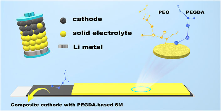
FIGURE 1. The schematic diagram of the experiment process and structure of ASSLB.
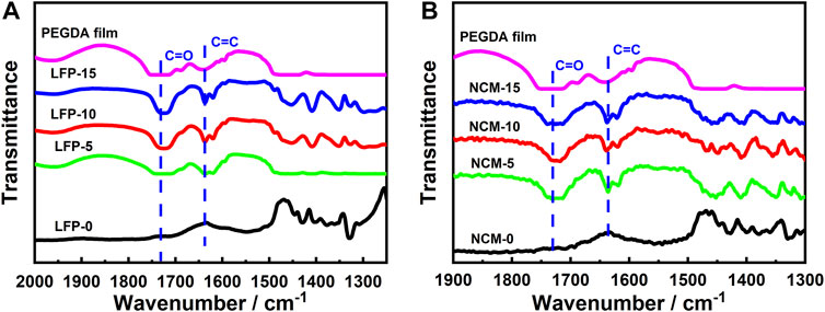
FIGURE 2. FTIR spectra of electrode samples: (A) LiFePO4 electrode material, LFP-0, LFP-5, LFP-10, LFP-15; (B) NCM811 electrode material, NCM-0, NCM-5, NCM-10, NCM-15.
The physical structure stability of SE and cathode material is key to affecting the performance of the cathode. That LiTFSI is a stable cathode component has been proved by previous research (Wu N. et al., 2020; Yu et al., 2021). Therefore, we only studied the compatibility between PEGDA and the cathode. We tested the XRD curve of all samples after they were placed in an argon atmosphere for 1 month. As shown in Figure 3, the diffraction patterns of the cathodes with PEGDA were the same as those of their control group; that is, PEGDA had no effect on the phase structure of the cathode materials. This shows that the two common cathodes, LiFePO4 and NCM811, can coexist with PEGDA stably without side reactions.
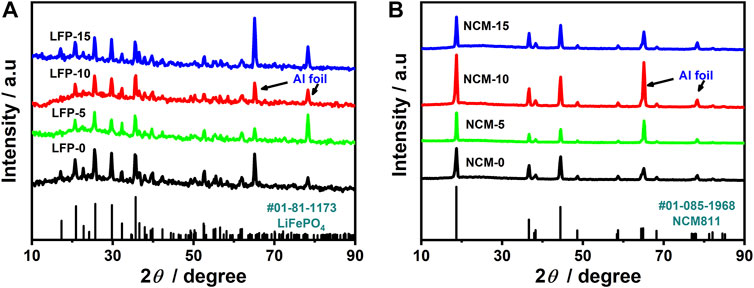
FIGURE 3. XRD curves of all electrodes: (A) LiFePO4 electrode, LFP-0, LFP-5, LFP-10, LFP-15; (B) NCM811 electrode, NCM-0, NCM-5, NCM-10, NCM-15.
The surface morphology of the cathode sheet will also have an objective impact on the battery performance. Therefore, we observed the surface morphology of the cathodes. The SEM test results are shown in Figure 4. Figures 4A–D show LiFePO4 composite cathodes; the surface of cathodes is flat and rich in pores, which is conducive to the infiltration of the electrolyte. The SEM of a partially enlarged view of cathodes (Figures 4E–H)showsa film on the surface of LiFePO4 particles, which should be PVDF. However, PVDF has poor conductivity to electrons and Li+, which will inevitably affect the Li+ transport of the cathode. Therefore, the introduction of PEGDA-based solid electrolytes will effectively improve the rate performance of cathodes. Figures 4I–L show the surface morphology of the NCM811 electrode. Due to the large particle size of NCM811 (10–20 μm), the surface looks uneven, but in fact, the cathode surface is relatively flat from the macro view. Similarly, Figures 4M–P give the image of a magnified NCM811 cathode. The surface of particles without SE (Figure 4M) is attached with thick massive PVDF and super P aggregates, which will seriously hinder the transmission of Li+. By introducing SE (Figure 4N–P), the adhesion of cathode particles is significantly improved. It is obvious that thin films (PEGDA-based SM and PVDF) and relatively dispersed super-P particles on the surface of NCM811 particles will be beneficial to the infiltration of electrolytes and the transport of Li+.
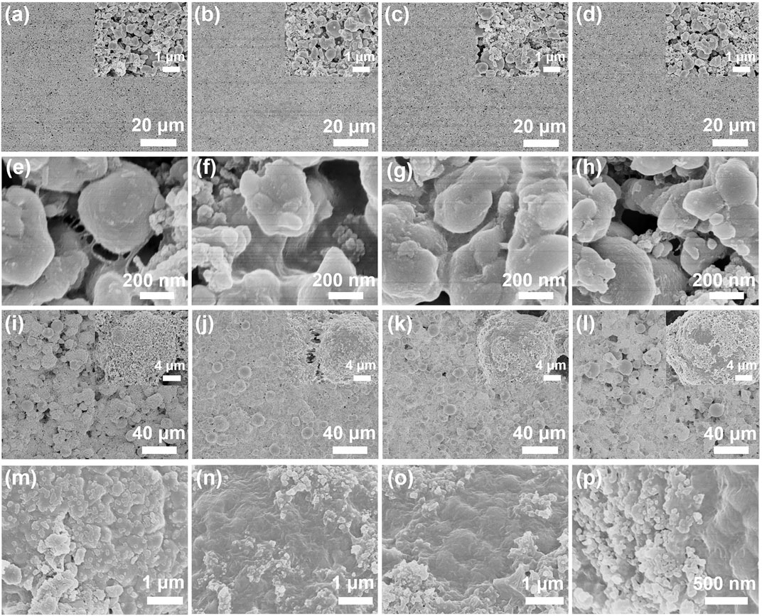
FIGURE 4. SEM photos of all samples: (A–D) LFP−0, LFP−5, LFP−10, LFP−15; (E–H) NCM811−0, NCM811−5, NCM811−10, NCM811−15; (I–P) partial enlarged image of cathodes.
Porosity and specific surface area are important performance indexes of advanced materials. For the cathode material, the larger specific surface area provides a larger contact area between the electrode material and the electrolyte, and the porous structure is conducive to the infiltration of the electrolyte. The specific surface area and pore diameter of the samples were obtained through the BET nitrogen adsorption test. The adsorption/desorption curves of several groups of samples showed the characteristic line of a mesoporous structure. The results are shown in Figure 5. In Figure 5A, the specific surface area of LFP-10 (16.43 m2 g−1) is significantly higher than that of LFP-0 (8.52 m2 g−1), which will help the contact between the electrolyte and the cathode, reduce polarization and improve rate performance. The test results of NCM811 material are shown in Figure 5B, but the specific surface area and porosity information of NCM-5 and NCM-0 are not obviously different, which may be related to the larger particle diameter of this material.
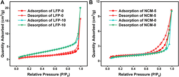
FIGURE 5. The N2 adsorption/desorption curves of some cathodes: (A) LFP-0 and LFP-10; (B) NCM-0 and NCM-5.
First, some batteries with liquid electrolyte were assembled, and the performance of the batteries was tested to determine whether the cathode performance improved. We use liquid electrolyte instead of solid electrolyte because of the poor ionic conductivity of SM, which makes the description of the discharge performance of electrode sheets under high current density incomplete. Therefore, the research starts with a conventional battery. Of course, we have also made corresponding tests on the application of cathodes in all-solid-state batteries (ASSLB), and the experimental results are provided at the end of this paper.
For LiFePO4 cathodes, the LFP-10 assembled battery has the best rate performance (Figure 6A), especially in the case of a high rate (≥5C). Specifically, LFP-10 has a discharge-specific capacity of 79.75 mAh g−1 at 5C, and it still has about 32.48 mAh g−1 even at 10C. In contrast, the capacity of the LFP-0 without SE decreased significantly at the rate of 2C. When the current density increased to 5C, the capacity approached zero. The improvement of rate performance is also fully reflected in another cathode material, NCM811 (Figure 6B). The discharge capacity of NCM-5 doped with 5% PEGDA-based SM is more reliable at high current density, and it has a capacity of nearly 100 mAh g−1 at 5C. By adjusting the doping ratio of PEGDA-based SM, the overall rate performance of the cathode shows a trend of first increasing and then decreasing. When the content of PEGDA-based electrolyte added to LiFePO4 reaches 15%, the rate performance of the cathode is not as good as that of LFP-10 but still higher than pure LiFePO4. Similarly, when the composition of PEGDA-based solid electrolyte exceeds 5%, the performance of NCM811 electrode material begins to decline. Therefore, it is necessary to control the content of the solid electrolyte to improve the electrode performance by doping SM. At the same time, the increase in rate performance reflects that the transmission resistance of Li+ decreases at a high current rate, which indicates that the doping of PEGDA-based SM can improve the transport of Li+.
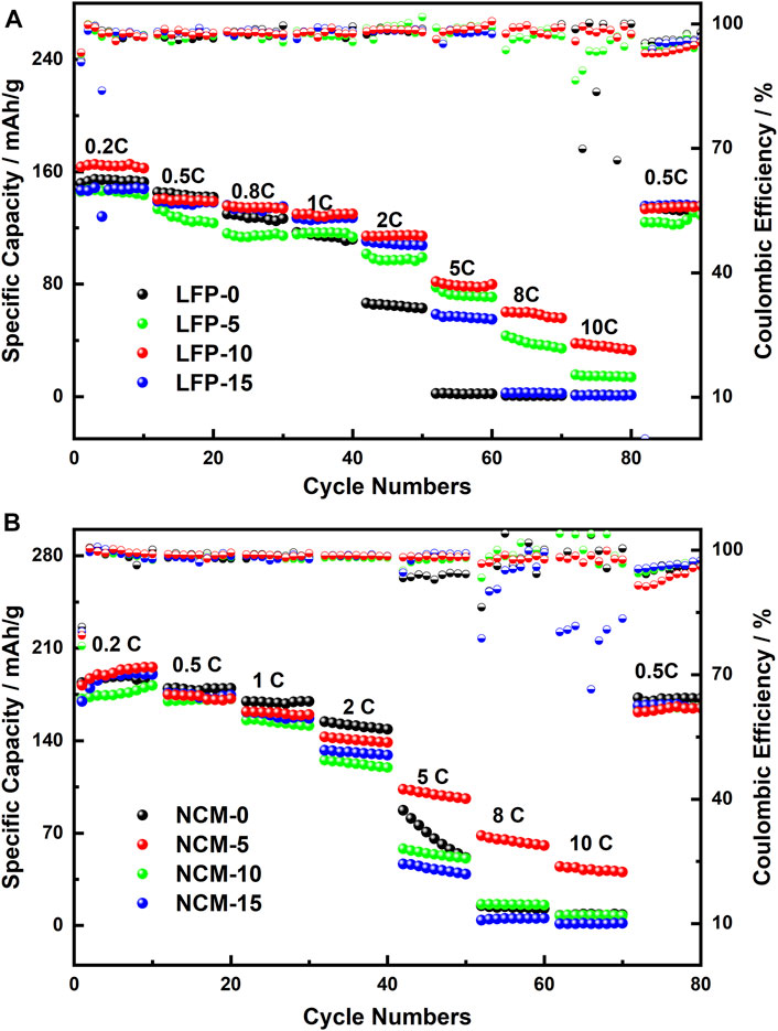
FIGURE 6. Rate performance of all samples: (A) LiFePO4; (B)NCM811.
In addition to helping to improve the rate performance of the cathode, as shown in Figure 7A, PEGA-based SM also plays a positive role in prolonging the cycle life of LiFePO4 series batteries. In our experiment, LFP-0 without any PEGDA showed significant capacity decay after only 20 cycles at a 0.5C rate, and the capacity decay reached 74.9 mAh g−1 after 200 cycles (the capacity retention rate was 54.8%). However, the LFP-10 still had 116.8 mAh g−1 capacity retention after 200 cycles (the capacity retention rate was 88.1%). Unfortunately, at the same current density, there is no significant difference in the long cycle performance of each of the NCM811 cathodes (Figure 7B). Their cycle curves all show a slow decline, which is mainly related to the poor structural stability of the NCM811 material itself. At the same time, the low charge-discharge rate of 0.5C may not be enough to show this difference.
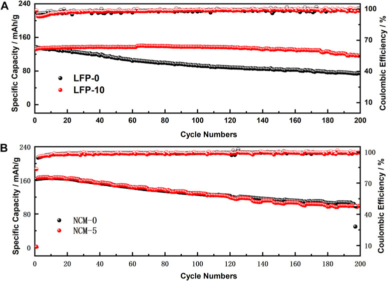
FIGURE 7. Long cycle performance of all samples: (A) LiFePO4; (B)NCM811.
The cathode in the battery system needs to undertake both the external transmission of electrons and the internal insertion and removal of ions. As we know, LiFePO4 is not an ideal electronic conductor, so the cathodes need to be doped with electronic conductors such as super P to ensure their function. The incorporation of ionic conductors into the cathode materials can obviously help LiFePO4 to embed and detach Li+. As an ionic conductor, the incorporation of PEGDA-based SE in the cathode enhances the ability to transport Li+, resulting in the reduction of Li+ transmission resistance. This is well verified in the EIS impedance data tested. As shown in Figure 8A, the impedance information of the battery can be simplified to the equivalent circuit in the illustration: Rct represents the charge-transfer resistance, shows the internal polarization process of the battery, and is usually the main part of the battery resistance; Rs refers to other resistance caused by non-polarization, such as electrolyte and separator resistance. The EIS of the two groups of batteries after 30 cycles are fitted through the equivalent circuit. The LFP-0 of the control group is 110.9 Ω after the cycle. The Rct of LFP-10 in the experimental group was 60.14 Ω, showing a significant decrease in impedance compared with the LFP-0. Meanwhile, for the EIS data after the cycle, the Li+ diffusion coefficients (DLi+) of LFP−0 and LFP−10 are calculated by using Formula 1 (Liu G. et al., 2018).
where R and T represent the gas constant and the absolute temperature of thermodynamics, respectively; n represents the number of electrons transferred by the particle motion: for Li+, this value is 1; S is the effective contact area between the cathode and the electrolyte; CLi represents the Li+ concentration in LiFePO4 material; K represents the charge transfer resistance in the impedance part of the battery relative to ω−1/2 slope. The calculation results are shown in Figure 8B. The DLi+ of the LFP-10 electrode reaches 1.08 × 10⁻¹⁴ cm2 s−1; compared with LFP-0 (8.57 × 10⁻¹⁵ cm2 s−1), it is improved by one order of magnitude. The result shows that the Li+ transport inside the cathode is significantly improved by the incorporation of PEGDA-based SE.
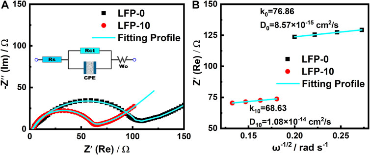
FIGURE 8. (A) Nyquist plots of electrodes LFP-0 and LFP-10; (B) diffusion coefficients of LFP-0 and LFP-10.
In addition to the AC impedance spectrum, CV data can also support the above view. Figure 9A shows the CV curve of LFP-10 under different scanning rates. With the increase of scanning rate, the oxidation potential of the cathode increases from 3.63 to 3.7 V, only a small increase. At the same time, the curve shows good symmetry, and no extra side reactions are found, which indicates that the reaction of the cathode in the process of Li+ insertion and removal is highly reversible, which brings more than 95% average Coulombic efficiency to the battery and improves the cycle life of LiFePO4. The DLi+ of the cathode is calculated using Formula 2, and the results are shown in Figure 9B.
where Ip is the peak current of the oxidation peak in the CV curve, n represents the number of electrons transferred by the Li+ movement and here takes the value of 1, S is the effective contact area between the electrode and the electrolyte, DLi+ is the diffusion coefficient, v is the preset sweep rate, and CLi is the lithium-ion concentration in the cathode. As shown in Figure 9B, the DLi+ of LFP-0 is 3.66 × 10⁻¹⁴ cm2/s, while the DLi+ of the LFP-10 cathode after doping and modification increased to 4.91 × 10⁻¹³ cm2/s, 13.4 times larger than the former. The larger Li+ diffusion coefficient means that the insertion and removal process of lithium ions in the electrode is smoother so as to alleviate the polarization of the cathode and improve the high-rate charging and discharging performance of the battery.
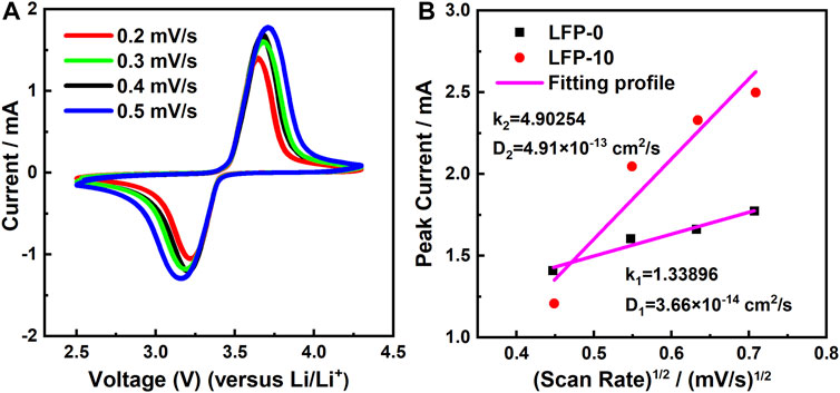
FIGURE 9. (A) CV curves of LFP-10 at different scan rates; (B) the linear fitting of the peak current versus (scan rate)1/2 for LFP-0 and LFP-10.
The following data relate to its application in an all-solid-state battery. SM is a composite polymer of PEGDA and PEO doped with LAZP and SCN. We tested the rate performance of ASSLB at 60°C. The test results are shown in Figure 10A. In the activation process of the solid-state battery, the capacity of both is almost the same. However, with the increase in charge-discharge rate, the capacity of LFP-0 decays rapidly, and only 10 mAh g−1 capacity is reserved at 2C. In contrast, LFP-10 has only a small decline in capacity at a low rate and has an average specific capacity greater than 100 mAh g−1 at 2C. It is worth mentioning that the performance of ASSLB at room temperature is poor, but LFP-10 can cycle at a small charge and discharge rate of 0.1C (Supplementary Figure S1), and LFP-0 cannot complete the cycle. The main reason for this difference is that SM particles lack fluidity and cannot spontaneously penetrate into cathode materials, making the contact between SM and LFP-0 a “rigid contact.” Poor interface contact leads to the increase of internal impedance and polarization of the battery, resulting in capacity attenuation. The comparison of charge-discharge curves in Figures 10B,C can also prove this point. For the full battery with LFP-10, the charge-discharge curve has a flat platform at each rate, while the capacity of the ASSLB with LFP-0 begins to decrease significantly even at a low current density of 0.2C. This is obviously not useful in commercial applications. The charging-discharging curves of the first cycle of the batteries are shown in Figure 10D. The platform of the battery where LFP-10 is located is maintained at 3.47 and 3.39 V, respectively. However, LFP-0 has obvious polarization during cycling, which will seriously affect the cycle life of the battery.
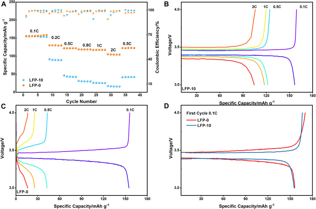
FIGURE 10. (A) Rate performance of ASSLB at 60°C; (B,C) charge-discharge curve of LFP-10 and LFP-0 at different rate; (D) charge-discharge curve of LFP-10 and LFP-0 at first cycle, 0.1C.
Through simple physical doping, adding solid electrolyte components to cathode materials can significantly improve the lithium-ion transport of the cathode. For LiFePO4, the optimum doping ratio is about 10%, while for NCM811, the ratio is 5%. In these composite samples, the DLi+ of LFP-10 is increased to 4.91 × 10⁻¹³ cm−2 s−1, which is 13.4 times that of the LFP-0 sample. The rate performance of the electrode under high current also improved. It has a capacity of 79.75 mAh g−1 at 5C, while the capacity of the original sample tends to zero at 2C. Another material shows similar behavior. Thanks to its high specific capacity, the discharge capacity of NCM-5 at 5C is higher than 100 mAh g−1, about 5 times that of the NCM-0. Improving Li+ transport performance is also beneficial to the ASSLB cycle. Closer contact reduces the polarization caused by the interface impedance of the battery. The LFP-10 battery has a stable charging and discharging platform, which ensures that the ASSLB has a capacity greater than 100 mAh g−1 at 2C (60°C).
The raw data supporting the conclusion of this article will be made available by the authors without undue reservation.
All authors listed have made a substantial, direct, and intellectual contribution to the work and approved it for publication.
Project supported by the National Natural Science Foundation of China (Grant No. 11704089), the Natural Science Foundation of Heilongjiang Province, China (Grant No. LH 2020E093), the China Postdoctoral Science Foundation (Grant No. 2017M611355), and Merit-based funding for returning overseas students in Heilongjiang Province.
We would like to thank the Merit-based funding for returning overseas students in Heilongjiang Province for their help.
The authors declare that the research was conducted in the absence of any commercial or financial relationships that could be construed as a potential conflict of interest.
All claims expressed in this article are solely those of the authors and do not necessarily represent those of their affiliated organizations or those of the publisher, the editors and the reviewers. Any product that may be evaluated in this article, or claim that may be made by its manufacturer, is not guaranteed or endorsed by the publisher.
The Supplementary Material for this article can be found online at: https://www.frontiersin.org/articles/10.3389/fenrg.2022.967756/full#supplementary-material
Bauer, W., and Nötzel, D. (2014). Rheological properties and stability of NMP based cathode slurries for lithium ion batteries. Ceram. Int. 40 (3), 4591–4598. doi:10.1016/j.ceramint.2013.08.137
Chen, S., Wen, K., Fan, J., Bando, Y., and Golberg, D. (2018a). Progress and future prospects of high-voltage and high-safety electrolytes in advanced lithium batteries: From liquid to solid electrolytes. J. Mat. Chem. A Mat. 6 (25), 11631–11663. doi:10.1039/c8ta03358g
Chen, S., Xie, D., Liu, G., Mwizerwa, J. P., Zhang, Q., Zhao, Y., et al. (2018b). Sulfide solid electrolytes for all-solid-state lithium batteries: Structure, conductivity, stability and application. Energy Storage Mater. 14, 58–74. doi:10.1016/j.ensm.2018.02.020
Chen, X., He, W., Ding, L.-X., Wang, S., and Wang, H. (2019). Enhancing interfacial contact in all solid state batteries with a cathode-supported solid electrolyte membrane framework. Energy Environ. Sci. 12 (3), 938–944. doi:10.1039/c8ee02617c
Chen, Y., Kang, Y., Zhao, Y., Wang, L., Liu, J., Li, Y., et al. (2021). A review of lithium-ion battery safety concerns: The issues, strategies, and testing standards. J. Energy Chem. 59, 83–99. doi:10.1016/j.jechem.2020.10.017
Ding, P., Lin, Z., Guo, X., Wu, L., Wang, Y., Guo, H., et al. (2021). Polymer electrolytes and interfaces in solid-state lithium metal batteries. Mater. Today 51, 449–474. doi:10.1016/j.mattod.2021.08.005
Dong, K., Xu, Y., Tan, J., Osenberg, M., Sun, F., Kochovski, Z., et al. (2021). Unravelling the mechanism of lithium nucleation and growth and the interaction with the solid electrolyte interface. ACS Energy Lett. 6 (5), 1719–1728. doi:10.1021/acsenergylett.1c00551
Edge, J. S., O'Kane, S., Prosser, R., Kirkaldy, N. D., Patel, A. N., Hales, A., et al. (2021). Lithium ion battery degradation: What you need to know. Phys. Chem. Chem. Phys. 23 (14), 8200–8221. doi:10.1039/d1cp00359c
Gonzalez Puente, P. M., Song, S., Cao, S., Rannalter, L. Z., Pan, Z., Xiang, X., et al. (2021). Garnet-type solid electrolyte: Advances of ionic transport performance and its application in all-solid-state batteries. J. Adv. Ceram. 10 (5), 933–972. doi:10.1007/s40145-021-0489-7
Kulova, T. L. (2020). A brief review of post-lithium-ion batteries. Int. J. Electrochem. Sci., 7242–7259. doi:10.20964/2020.08.22
Liu, B., Jia, Y., Yuan, C., Wang, L., Gao, X., Yin, S., et al. (2020). Safety issues and mechanisms of lithium-ion battery cell upon mechanical abusive loading: A review. Energy Storage Mater. 24, 85–112. doi:10.1016/j.ensm.2019.06.036
Liu, G., Chi, Q., Zhang, Y., Chen, Q., Zhang, C., Zhu, K., et al. (2018a). Superior high rate capability of MgMn2O4/rGO nanocomposites as cathode materials for aqueous rechargeable magnesium ion batteries. Chem. Commun. 54 (68), 9474–9477. doi:10.1039/c8cc05366a
Liu, K., Liu, Y., Lin, D., Pei, A., and Cui, Y. J. S. a. (2018b). Materials for lithium-ion battery safety. Sci. Adv. 4 (6), eaas9820. doi:10.1126/sciadv.aas9820
Liu, Y., Lin, D., Yuen, P. Y., Liu, K., Xie, J., Dauskardt, R. H., et al. (2017). An artificial solid electrolyte interphase with high Li-ion conductivity, mechanical strength, and flexibility for stable lithium metal anodes. Adv. Mat. 29 (10), 1605531. doi:10.1002/adma.201605531
Mahmood, A. (2015). Recent research progress on quasi-solid-state electrolytes for dye-sensitized solar cells. J. Energy Chem. 24 (6), 686–692. doi:10.1016/j.jechem.2015.10.018
Manthiram, A. (2020). A reflection on lithium-ion battery cathode chemistry. Nat. Commun. 11 (1), 1550. doi:10.1038/s41467-020-15355-0
Martins, L. S., Guimaraes, L. F., Botelho Junior, A. B., Tenorio, J. A. S., and Espinosa, D. C. R. (2021). Electric car battery: An overview on global demand, recycling and future approaches towards sustainability. J. Environ. Manage. 295, 113091. doi:10.1016/j.jenvman.2021.113091
Ould Ely, T., Kamzabek, D., and Chakraborty, D. (2019). Batteries safety: Recent progress and current challenges. Front. Energy Res. 7, 71. doi:10.3389/fenrg.2019.00071
Rajagopal, R., Subramanian, Y., and Ryu, K. S. (2021). Improving the electrochemical performance of cathode composites using different sized solid electrolytes for all solid-state lithium batteries. RSC Adv. 11 (52), 32981–32987. doi:10.1039/d1ra05897e
Shiraki, S., Shirasawa, T., Suzuki, T., Kawasoko, H., Shimizu, R., and Hitosugi, T. (2018). Atomically well-ordered structure at solid electrolyte and electrode interface reduces the interfacial resistance. ACS Appl. Mat. Interfaces 10 (48), 41732–41737. doi:10.1021/acsami.8b08926
Wang, X., Wei, X., Zhu, J., Dai, H., Zheng, Y., Xu, X., et al. (2021). A review of modeling, acquisition, and application of lithium-ion battery impedance for onboard battery management. eTransportation 7, 100093. doi:10.1016/j.etran.2020.100093
Wu, H., Jia, H., Wang, C., Zhang, J. G., and Xu, W. (2020a). Recent progress in understanding solid electrolyte interphase on lithium metal anodes. Adv. Energy Mat. 11 (5), 2003092. doi:10.1002/aenm.202003092
Wu, N., Chien, P. H., Li, Y., Dolocan, A., Xu, H., Xu, B., et al. (2020b). Fast Li(+) conduction mechanism and interfacial chemistry of a NASICON/polymer composite electrolyte. J. Am. Chem. Soc. 142 (5), 2497–2505. doi:10.1021/jacs.9b12233
Xin, C., Wen, K., Xue, C., Wang, S., Liang, Y., Wu, X., et al. (2021). Composite cathodes with succinonitrile‐based ionic conductors for long‐cycle‐life solid‐state lithium metal batteries. Batter. Supercaps 5 (1), e202100162. doi:10.1002/batt.202100162
Yu, X., Liu, Y., Goodenough, J. B., and Manthiram, A. (2021). Rationally designed PEGDA-LLZTO composite electrolyte for solid-state lithium batteries. ACS Appl. Mat. Interfaces 13 (26), 30703–30711. doi:10.1021/acsami.1c07547
Yun, B. N., Lee, S., Jung, W. D., Shin, H. J., Kim, J. T., Yu, S., et al. (2022). Facile method for the formation of intimate interfaces in sulfide-based all-solid-state batteries. ACS Appl. Mat. Interfaces 14 (7), 9242–9248. doi:10.1021/acsami.1c24895
Keywords: lithium ion transport, rate performance, cathode, solid electrolyte, interface impedance
Citation: Zhang Y, Zhu B, Chi Q, Gao H, Zhang C, Zhang T, Zhu K and Cao D (2022) Improvement in lithium-ion transport performance of cathodes by PEGDA-based solid-state electrolyte. Front. Energy Res. 10:967756. doi: 10.3389/fenrg.2022.967756
Received: 13 June 2022; Accepted: 28 June 2022;
Published: 22 August 2022.
Edited by:
Weibo Hua, Xi’an Jiaotong University, ChinaReviewed by:
Mingzhe Chen, Nanjing University of Science and Technology, ChinaCopyright © 2022 Zhang, Zhu, Chi, Gao, Zhang, Zhang, Zhu and Cao. This is an open-access article distributed under the terms of the Creative Commons Attribution License (CC BY). The use, distribution or reproduction in other forums is permitted, provided the original author(s) and the copyright owner(s) are credited and that the original publication in this journal is cited, in accordance with accepted academic practice. No use, distribution or reproduction is permitted which does not comply with these terms.
*Correspondence: Qingguo Chi, cWdjaGlAaG90bWFpbC5jb20=
Disclaimer: All claims expressed in this article are solely those of the authors and do not necessarily represent those of their affiliated organizations, or those of the publisher, the editors and the reviewers. Any product that may be evaluated in this article or claim that may be made by its manufacturer is not guaranteed or endorsed by the publisher.
Research integrity at Frontiers
Learn more about the work of our research integrity team to safeguard the quality of each article we publish.