 Bo Tian1,2*
 Junhu Gao2Qiang Guo2Xiaoming Zhu2Hao Zhang2Wei Zhu2Xu Hao2Chaohe Yang1Yong Yang2Yong-Wang Li2
- 1State Key Laboratory of Heavy Oil Processing, China University of Petroleum (East China), Shandong, China
- 2National Energy Center for Coal to Liquids, Synfuels China Technology Co., Ltd, Beijing, China
The direct coal liquefaction process usually produces a liquefaction residue of about 30% of its coal feed. The effective utilization of the coal liquefaction residue (CLR), which contains about 80% organic matter, is of great significance for improving the oil yield of the direct liquefaction process and reducing the amount of pollution emitted from this oil-containing organic solid waste. In this study, the CLR fluidized bed pyrolysis process was studied through a fluidized bed reactor pyrolysis experiment and steady-state thermal analysis. The characteristics of CLR were first analyzed, and then the pyrolysis experiment was conducted in a fluidized bed reactor system. The experiment results show that the oil yield is 34.81% at 540°C for an ash-free feedstock using a fluidized bed pyrolysis reactor. Based on the pyrolysis experimental data and the Aspen Plus software platform, the fluidized bed pyrolysis reactor, fractionation column, coke burner, gasifier, and other equipment were modeled to compare four different process schemes. CLR pyrolysis is an endothermic reaction, and its heat is usually supplied by coke combustion, which produces significant CO2 emissions. Case studies of the pyrolysis process were performed in detail in order to reduce CO2 emissions. Thermal efficiency, carbon efficiency, solid waste discharge, and CO2 emissions of the different schemes were compared, and a flexible fluidized pyrolysis (FFP) process coupled with water electrolysis was proposed. The introduction of green hydrogen and green oxygen to the process can realize near-complete utilization of carbon and hydrogen elements in the CLR and produce high-quality liquid fuels and syngas (for further chemical synthesis), and this new process can achieve almost near-zero CO2 emission in the entire unit. This process principle can also be applied to the CO2 emission reduction of organic solid waste pyrolysis, catalytic fluid cracking, fluid coking, and so on.
Introduction
China’s energy situation of “rich in coal, less in oil, and poor in gas” determines the clean and efficient conversion and utilization of coal, which will remain the ballast of China’s energy for a certain time in the future (Xiang et al., 2014), and the key coal conversion technologies are indirect coal liquefaction and direct coal liquefaction. Direct coal liquefaction (DCL) is a process for converting coal to liquid fuels by dissolving coal in an organic hydrogen donor solvent in the presence of hydrogen and a catalyst under high temperature and pressure. The typical pressure and temperature are 19–20MPa and 450°C, respectively, (Shu, 2009). It was reported that coal can also be liquefied at mild conditions of 5–8 MPa (Yang et al., 2020). Due to the existing ash content in coal, the coal liquefaction catalyst, and the incomplete reaction of organic matter in coal liquefaction, solids are always left in the effluent of the reactor. In discharging these solids from the separate unit, it is usually inevitable that some heavy oil accompanies them to ensure fluidity in the pipes out of the vacuum distillation unit. The direct coal liquefaction process usually produces a coal liquefaction residue (CLR) of about 30% of its coal feed (Xu et al., 2014), and there is more than 80% organic matter in the CLR. Therefore, effective utilization of the organic material in the coal liquefaction residue is of great significance for improving the oil yield of the direct liquefaction process and reducing the amount of pollution emissions from this oil-containing organic solid waste.
At present, the reported treatment technologies of the coal liquefaction residue include direct gasification, fuel for boiler combustion, coking, pyrolysis, carbon material preparation, etc. (Winschel and Burke, 1989; Cui et al., 1999; Zhou et al., 2007; Li et al., 2010; Liu, 2012; Chen et al., 2020; Tian et al., 2022) Among them, CLR pyrolysis technology, which can maximize the light oil yield from the oil containing feedstock, is considered the most promising and feasible path in the future. The reported pyrolysis studies of the coal liquefaction residue mainly focus on the use of a Thermal Gravimetric Analyzer (TGA) instrument or fixed-bed tube reactor (Li et al., 2010; Liu, 2012), which can only provide qualitative analysis results. Some groups used a continuous stirred coking unit (CSCU) to test the reaction performance of CLR fluid coking (Winschel and Burke, 1989). Unfortunately, no further study was reported. In this study, the fluidized bed pyrolysis experiments of the CLR were studied, and the fluidized bed reactor has the best temperature uniformity both in axial and radial directions, which is beneficial for the pyrolysis reaction in improving the oil yield and reducing the coking rate (Yang et al.,; Wang and Qi, 2012; kun et al., 2011; Yang et al., 2017).
Today, reducing carbon dioxide emissions has become an urgent global issue in order to delay global warming. Pyrolysis is an endothermic reaction, and its heat is usually supplied by coke combustion, which will result in CO2 emissions. Based on the CLR pyrolysis experimental study results and Aspen Plus simulation software, the four different fluidized bed pyrolysis process schemes were modeled and the case studies of reducing CO2 emissions from the pyrolysis process were performed. Eventually, solar water electrolysis for green hydrogen and green oxygen generation was also combined with the proposed fluidized bed pyrolysis process to optimize the carbon reduction effect (Xiang et al., 2022).
2 Experimental
2.1 Analysis of the coal liquefaction residue
2.1.1 Analysis method
1) Feed raw material and pretreatment
The coal liquefaction residue was taken from a coal direct liquefaction demonstration plant in China. 300-g samples were dried in an oven which was kept at a constant temperature at 105°C for 2–3 h for each experiment and crushed to about 200 mesh particles for raw material analysis, such as softening point, ash content, density, proximate analysis, ultimate analysis, and organic matter extraction (Li et al., 2010) (Liu, 2012).
2) Softening point test method
The softening point test method for the coal liquefaction residue is ASTMD3461-83, and the softening point analysis instrument is the WQD-1A drop point softening point tester.
3) Ash content test method
The ash content test method for the coal liquefaction residue is National Standard GB/T 29748-2013 (Li et al., 2010) (Liu, 2012).
4) Density analysis method
The density analysis of the coal liquefaction residues is tested with reference to GB/T 13377-2010 (Determination of Density or Relative Density of Crude Oil and Liquid or Solid Petroleum Products-Capillary Stopper Pycnometer and Double Capillary Pycnometer with Scale) and the HCR2000 petroleum density pycnometer (Li et al., 2010) (Liu, 2012).
5) Proximate analysis and ultimate analysis
The CLR proximate analysis and ultimate analysis use the national standard GB/T212-2001 and GB/T476-2001 analytical methods. The organic element analysis instrument model is the Elementar vario EL element analyzer. The sulfur measurement is made using the ZCS-1 type intelligent sulfur measuring instrument of Xuzhou Analysis Instrument Factory (Li et al., 2010) (Liu, 2012).
6) Extraction analysis method
For the rapid solvent extraction analysis of coal liquefaction residues, the solvents of n-hexane toluene, and tetrahydrofuran (THF) were used as extraction agents. The extraction methods and procedures refer to the existing analysis standard NB/T-12005-2016 of the National Energy Administration (Li et al., 2010) (Liu, 2012).
2.2 Fluidized bed pyrolysis experiment
2.2.1 Experimental apparatus and method
The CLR pyrolysis experiment was performed in a fluidized bed reactor to investigate the influence of reaction temperature conditions on the product yield and distribution and provide detailed reaction data for further process simulation and optimization.
The experimental apparatus of the fluidized bed reactor is shown in Figure 1. 400 g of the coal liquefaction residue is added into the raw material kettle for each experiment and heated up to 150–250°C according to the experimental requirements before the pyrolysis experiment starts. The high-pressure N2 is used to press the CLR into the reactor through the feed nozzle. Water vapor enters the reactor as a fluidized gas. The reaction temperature was tested in the range of 500–620°C. The product oil and gas vapor are discharged from the top of the reactor. The heavy oil and light oil are cooled stepwise and collected in the hot and cold traps. The tailgas enters the gas measurement and analysis system. After reaction, the liquid product and solid coke product from the reactor were collected for further analysis.
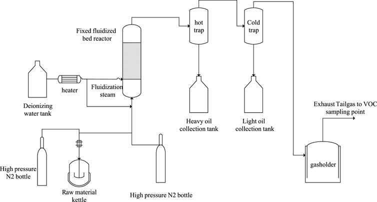
FIGURE 1. Flow diagram of the fluidized bed pyrolysis experimental apparatus. Bo Tian, female, (1981-), PhD, permanent resident of South Africa, Native place: Jiuquan, Gansu Province, Professoriate senior engineer, Technology development lead a n d senior Project technical leader, Fluidized bed process technical expert, 1. China University of Petroleum (East China), State Key Laboratory of Heavy Oil, 2. Synfuels China Technology Co., Ltd., National Energy Coal-based liquid fuel Research Center, Main research directions: coal-to-oil and chemicals, carbon-containing resource pyrolysis technology research and development, organic solid waste resource transformation, applied basic research, reaction process research, engineering technology development and design, process simulation and optimization, and engineering amplification, etc.
2.2.2 Product yield calculation method
The yield of fluidized bed pyrolysis products was calculated in two methods: water and ash-free feed basis or THF soluble feed basis. The yield calculated in THF soluble feed basis may be more accurate because the THF insoluble substances in the raw material are usually inert in the pyrolysis reaction and are directly converted into coke in the product. The dry gas and LPG of the product are calculated by the mass flow rate of each product in the actual exhaust gas. The amount of oil in different fraction sections is determined according to the simulated distillation process distribution of the actual received oil products, and the mass of the C5+ component in the exhaust gas is considered and added into the distillation of the naphtha fraction. For the coke yield calculation for water and ash-free feed basis, the total coke mass includes the coke produced by pyrolysis reaction and inert organic matter directly from the raw material, excluding the mass of inorganic ash brought into the raw material. For the coke yield calculation of the THF soluble basis, the coke yield is exactly the organic coke produced from the pyrolysis reaction.
2.2.2 Product analysis method
1) Tail gas analysis
For tail gas composition analysis, the Agilent 7890A gas chromatograph (GC) was used with the national standard GB/T 27885-2011.
2) Oil product analysis
For the simulated distillation analysis of the oil product, the Agilent 7890A gas chromatograph was used according to the national standard NB/SH/T 0879-2014 method.
3) Char ultimate analysis
The ultimate analysis of the char samples adopts the national standard of GB/T476-2001 analytical methods by the same analytical equipment as in Section 2.1.1.
2.3 Experimental results and discussion
2.3.1 Raw material analysis results and discussion
Property analysis of the coal liquefaction residue is of great significance to its utilization prospects and process scheme selection. The analysis results of the raw material properties of the coal liquefaction residue are shown in Table 1.
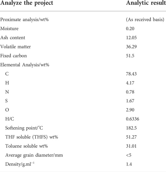
TABLE 1. Analysis results of coal liquefaction residue properties.
As can be seen from Table 1, the water content of the coal liquefaction residue is low, the ash content is 12.05%, the fixed carbon is 51.27%, and the volatile 36.29%. The ash in the coal liquefaction residue mainly comes from the ash in the raw coal and the catalyst added in the direct liquefaction reaction process. Because the water in the coal has been removed during the reaction process, a small amount of water may come from the water absorbed when the raw material is placed in the air. A large amount of ash will cause the calorific value of coke after pyrolysis to decline, and it is difficult to use it. Fixed carbon is mainly derived from unreacted coal and bituminous substances, and volatilization is the entrained heavy oil. It can be seen from the proximate analysis that if the volatile utilization of the raw material can be maximized to produce oil and the rational use of fixed carbon, it is very important for the high-value utilization of the coal liquefaction residue. It can be seen from the ultimate analysis that hydrocarbon elements account for more than 82% and the H/C element ratio is 0.6336, which has a very good utilization value. The softening point of the coal liquefaction residue is 180.2°C, which is closely related to the operating condition of the device, usually between 170 and 190°C. If the softening point is less than 170°C and the amount of heavy oil contained in the residue is large, it constantly affects the oil yield, and the residue is not easy to form. If the softening point is higher than 190°C, the liquidity is poor, making it easy to undergo coke formation and block the equipment pipeline, affecting the normal operation of the device. In addition, for the fluidized bed pyrolysis process, the softening point of the coal liquefaction residue directly affects the raw material feed and the flow condition in the fluidized pyrolysis reactor. It can be seen from the extraction results that the soluble matter content of tetrahydrofuran (THF) soluble is 51%, and it is the key index of pyrolysis of the coal liquefaction residue. Usually only THF Soluble matter undergoes pyrolysis or coke reaction, and the pyrolysis method makes the soluble matter crack into lighter oil and gas products, which is also the key benefit of pyrolysis. Therefore, the yield of pyrolysis oil is compared by using the Ash-free method and the THF soluble matter group method in Table 2.
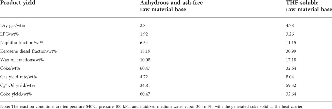
TABLE 2. Distribution of pyrolysis experimental data products of the coal liquefaction residue fluidized bed.
2.3.2 Fluidized pyrolysis experimental results and discussion
Table 2 shows the experimental results of the pyrolysis of the coal liquefaction residue in a fixed fluidized bed reactor. In the table, the yields of dry gas, LPG, C5+ ∼ 180°C naphtha fraction, 180–360°C diesel fraction, > 360°C wax oil fraction, and coke of the product are calculated according to the anhydrous ash free organic matter and tetrahydrofuran (THF) soluble organic matter of the raw material as reactants.
It can be seen that the oil yield is 34.81 wt% for the ash-free raw material base and 67.39 wt% for the THF-soluble raw material base, which shows that the fluidized bed pyrolysis process can effectively recover the oil in the raw material and convert some difficult heavy asphalt into light oil, which improves the yield of oil and realizes the light utilization of heavy oil. Compared with previous fixed-bed pyrolysis results research, the best oil yield is around 16 wt% at 600°C (Xu et al., 2014) (Liu, 2012) and while in the TGA micro reactor in N2 atmospheres, the total weight loss for oil and gas was reported to be 34.2 wt% and 33.74 wt% from two different researchers (Xu et al., 2014) (Li et al., 2010). This is mainly due to the fact that in a fluidized bed, the heat transfer efficiency is high, the temperature in the bed is easy to maintain uniform, and there is uniform gas–solid two-phase mixing of the reaction material. This is very important for the reaction process with large thermal effects and those sensitive to temperature, such as pyrolysis. The fluidized bed reactor has the best temperature uniformity both in axial and radial directions, which is beneficial for the pyrolysis reaction to improve the oil yield and reduce the coking rate. In addition, the coke product is less likely to agglomerate than in a fixed-bed reactor due to the high-speed uniform dispersion and flow of the coke inside a fluidized bed. In the fixed-bed reactor, 2∼3 g of the raw coal residue was packed in the tube reactor during the pyrolysis reaction, and it had poorer heat transfer or uneven heat transfer, which could have impacted negatively on the pyrolysis reaction. In contrast, for the TG thermal reaction analysis, 20 mg of the raw coal residue was used in the TGA micro reactor. TGA is a thermal analysis technique that is usually used to study the thermal stability and composition of materials. It is not affected by mass and heat transfer effects; hence, the gas and oil yield is much higher than in fixed-bed and fluidized bed reactors.
Due to the high content of asphalt organic matter in the raw material and the unconverted coal, most or all of the feed organic substances will produce coke. The utilization of this coke will not only affect the economy of the process but also the disposal of inorganic materials and the coke, which also has a certain impact on the environment. If coke combustion provides energy for pyrolysis reaction, it will also lead to CO2 emission problem. How to reduce CO2 emissions is vital for the process; therefore, the process optimization of the coke heating part and coke usage is the focus of the next section of this study.
3 Fluidized pyrolysis process simulation and optimization
The complete process of the coal liquefaction residue not only includes the pyrolysis reaction part and the oil and gas fractionator part but also includes the combustion or gasification part that provides heat for the reaction. Moreover, the process setting of the coking and gasification parts will determine the thermal efficiency and carbon efficiency of the whole process, which is the second focus of this study. According to the two different schemes of coke burning heating and gasification heating, this technology is divided into two schemes: fluidized pyrolysis and flexible pyrolysis. In addition, according to the oxidant part of the process, using air or oxygen, it is also divided into four process schemes: fluidized pyrolysis air combustion, fluidized pyrolysis oxygen combustion, flexible pyrolysis air gasification, and flexible pyrolysis oxygen gasification. The four specific process schemes were simulated as below.
3.1 Process flow description
1) Fluidized pyrolysis air combustion process (Case 1)
Case 1:. The fluidized pyrolysis air combustion coke process includes a fluidized pyrolysis reactor, coke air burner, oil and gas fractionator, and a fuel gas treatment system. The process requiring excess coke exhausts part of the coke.The flow of the fluidized pyrolysis air combustion process is shown in Figure 2. The coal liquefaction residue and water vapor enter the reactor through the nozzle atomization, and the organic matter in the raw material undergoes thermal cracking reactions and condensation coke reactions. The generated oil and gas are discharged from the top of the reactor into the fractionation column, distilled, and cut into pyrolysis-rich gas, pyrolysis sewage, naphtha, kerosene and diesel distillate, wax oil distillate, and other products. The generated coke absorbs the water vapor and enters the coke burner. A certain amount of coke reacts with the air. The heat generated is for the heat balance of the whole system, and the excess coke is discharged from the system. The fuel gas generated by the combustion reaction enters the fuel gas treatment system, recovers heat, removes dust, and cleans it. The heat required by the pyrolysis reactor is provided by the circulation of hot focal particles. The pyrolysis reaction temperature was controlled at 500–620°C, and the coking reaction temperature was controlled at 650–750°C. Thermal cracking and condensation of all hydrocarbons occur in the fluidized bed pyrolysis reactor, which follows the free radical chain reaction mechanism. Complete combustion and partial combustion reactions of coke occur in the fluidized bed coke reactor, and the chemical reaction equation is as follows: R1 and R2. If the fuel gas contains CO, excess air needs to be further burned before heat exchange and cooling until all of it is converted into CO2. The process oxidizer uses air because air contains a large amount of inert nitrogen, so it is required to consume additional coke and heat up the nitrogen, resulting in a decrease in thermal efficiency.Full combustion of coke: C + O2 = CO2 -394.1 kJ/mol (R 1)Incomplete combustion of coke: C + 1/2 O2 = CO -110.4 kJ/mol (R2)
2) Fluidized pyrolysis oxygen combustion process (Case 2)
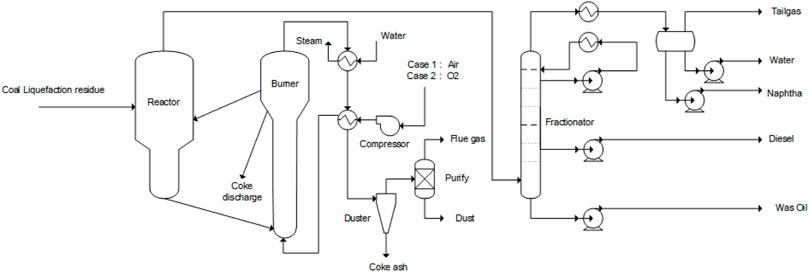
FIGURE 2. Fluidized pyrolysis process (case 1: fluidized pyrolysis with air combustion; Case 2 fluidized pyrolysis with oxygen air combustion).
Case 2:. The fluidized pyrolysis oxygen air combustion coke process includes a fluidized pyrolysis reactor, coke oxygen burner, oil and gas fractionator, and a fuel gas treatment system. The process requiring excess coke exhausts part of the coke.Compared to the Case 1 air fluidization pyrolysis process, Case 2 uses pure oxygen for coke burning and combustion, and the rest of the equipment is the same as in Case 1, as shown in Figure 2. Using pure oxygen will hopefully reduce the size of the burner. The source of oxygen can be from an air separation unit in existing plants or from green oxygen from water electrolysis, a byproduct of the electrolysis of water hydrogen production plant.
3) Flexible fluidized pyrolysis air gasification process (Case 3)
Case 3:. The flexible fluidized pyrolysis air gasification process includes a fluidized pyrolysis reactor, air coke gasifier, oil and gas fractionator, and a fuel gas treatment system. It is a process of complete coke gasification that discharges only inorganic solids and produces low calorific value fuel gas.The flow diagram of the flexible fluidized pyrolysis process is shown in Figure 3. Compared with the fluidized pyrolysis process in Figure 2, the heat supply part of the flexible fluidized pyrolysis process utilizes the mode of coke gasification and coke heat exchange to produce fuel gas or syngas instead of the air coke combustion in Case 1, and the remaining pyrolysis reaction and fractionation part are the same as the fluidized pyrolysis of Case 1. The coke generated by the pyrolysis reaction is carried into the heat exchange room through effluent gas. After heat exchange with the high-temperature fuel gas generated after the gasification reaction, one part returns to the reactor to provide heat, and the rest enters the gasification device for gasification reaction. The remaining solid after the gasification reaction is discharged, or it is mixed with the cold coke particles from the pyrolysis reactor back into the heat transfer chamber. The temperature of the gasification reaction is at 900–1,200°C, and the temperature of the heat transfer chamber is controlled at 650–750°C. For the flexible fluidized pyrolysis air combustion process, the oxidant for the gasification reaction adopts air, and all coke undergoes gasification reaction. After gasification reaction, low calorific value fuel gas is generated, which can be supplied to other units as fuel gas in the whole plant. This unit, however, only discharges the inorganic solids after high-temperature treatment, which can achieve environmental protection emission standards. The fuel gas leaving the heater is heat exchanged by the built-in cyclone separator, external high-pressure steam generator, oxygen water heater, and air heater, then enters the external high-efficiency gas-solid separator to remove the entrained dust, and is then sent to the desulfurization and purification device to produce low sulfur and low calorific value fuel gas.
4) Flexible fluidized pyrolysis oxygen gasification process (Case 4)
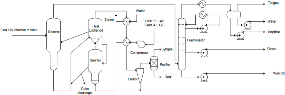
FIGURE 3. Flexible fluidized pyrolysis (case 3: flexible fluidized pyrolysis air gasification; case 4 flexible fluidized pyrolysis oxygen gasification).
Case 4:. The flexible fluidized pyrolysis oxygen gasification process includes a fluidized pyrolysis reactor, oxygen coke gasifier, oil and gas fractionator, and a syngas treatment system. This process of coke is complete gasification, and only discharged inorganic solids, with high calorific value syngas, can be used in the production of chemicals.Based on the flexible fluidized pyrolysis process of Case 3, Case 4 introduces pure oxygen as an oxidant for the gasification reaction, which can reduce the heat loss of nitrogen heating and improve the calorific value of the generated gas and produce direct syngas (H2 and CO) for downstream syngas production. This amount of syngas can be combined with green hydrogen to be used as feed gas for methanol or olefin production.
3.2 Process simulation assumptions and physical property selection
The simulation benchmark of the abovementioned four process schemes is the annual treatment capacity of the coal liquefaction residue of 700,000 tons, that is, 87,500 kg/h. The four fluidized pyrolysis reaction process parts are the same, while the effects of different coke combustion processes and gasification processes were compared. The ASPEN Plus simulation software platform is used to model these four process schemes. The mass balance, energy balance, thermal efficiency, and carbon efficiency, as well as CO2 emission and solid discharge, were analyzed and compared.
The thermodynamic equation of the Soave–Redlich-Kwong (SRK) equation is used for pyrolysis and fractionation partial simulation, and the Peng–Robson equation of state is used to simulate the combustion and gasification part. The simulation of the reactions in the fluidized pyrolysis reactor was performed using the RYield yield reactor model to calculate the product distribution after the reactions based on the experimental results in Table 2. The fractionation tower uses the PetroFrac tower module combined with the design provisions to calculate the product distribution of different distillation processes. The coke combustion reactor was simulated by a RStoic reactor, considering two reactions, R1 and R2, and containing the CO/CO2 in the tail gas according to the experimental coking reaction. The selectivity of the proportional adjustment reaction is carried out as follows: if the exhaust gas contains CO, the CO will be completely converted into CO2 with the RStoic reactor module at the combustion reactor, thus calculating the carbon balance and the CO2 emission reduction effect. According to the H content in coke, the reaction of H2 and O2 to generate water is adopted, and the combustion heat of H2 is considered. For the coke gasification reaction, the RYield yield reactor and the RGibbs reactor were used to simulate the gasification process and adjust the proportion of key components in the product according to the reaction equilibrium temperature distance method to be close to the actual composition reported in the literature (Chen et al., 2020). The calculation method of the heat loss in the heat balance of the reactor, burner, and gasifier is obtained from the estimated heat exchange area of the estimated major equipment and the heat dissipation coefficient with reference to the fluidized catalytic cracking (FCC) process (Cao et al., 2000).
In this study, the thermal efficiency calculation adopts the ratio of the low calorific value of the whole process unit before and after the reaction, that is, the ratio of the low calorific value of all products to the low calorific value of all raw materials. The comparison of process schemes of the units only considers the difference in coke heating parts, and the other equipment is basically the same. Therefore, the change in energy consumption of the unit can be judged by the thermal efficiency. Carbon efficiency refers to the mass ratio of carbon elements in all products to carbon elements in raw materials, which can judge the transform direction of carbon in raw materials and the amount of CO2 produced.
3.3 Process simulation/optimization results and discussion
1) Material balance of the fluidized pyrolysis reaction part
The abovementioned four coal liquefaction residue treatment process schemes have the same process of fluidized pyrolysis reaction parts, and the material balance of the reaction is shown in Table 3. For a direct coal liquefaction plant with an oil output of 1 million tons/year, the by-product coal liquefaction residue is about 700,000 tons/year. If the fluidization pyrolysis plant with a coal liquefaction residue treatment capacity of 700,000 tons/year is designed, the annual yield of C3 + oil products is 225,600 tons/year, which is equivalent to an increase of 22% of the production capacity. At the same time, 17,200 tons/year of dry gas will be produced and processed in the downstream tail gas treatment unit. Fluidization pyrolysis produces about 371,400 tons/year of organic coke per year and 84,000 tons/year of inorganic ash at the same time. The organic coke produced by fluidized pyrolysis is attached to the inorganic ash, usually coke particles in the range of 10–100 microns. The granular coke with high ash content is difficult to be further processed and utilized. Only when the organic coke is burned or gasified can the inorganic ash be discharged up to the standard.
2) Heat balance analysis
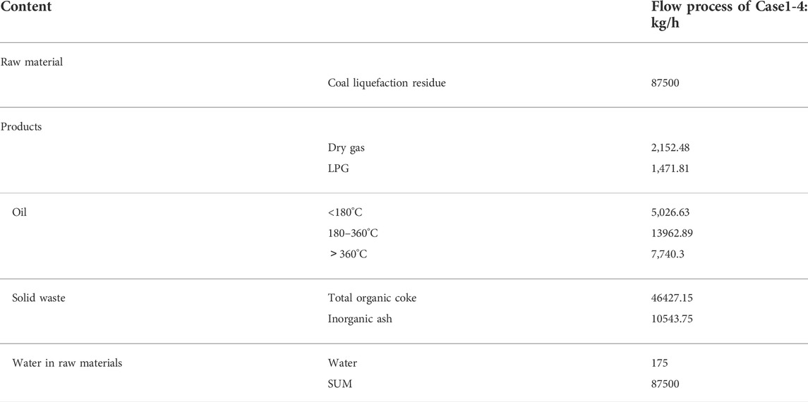
TABLE 3. Material balance of reaction part of the fluidized bed.
The heat balance calculation results of two different coke burning/combustion methods of the fluidized pyrolysis process are shown in Table 4. For the pyrolysis reaction of the coal liquefaction residue, a raw material with a high coke generation rate, and because the condensation coke generation is an exothermic process, which will offset part of the heat absorbed by cracking, the total heat absorbed by the reaction is less, and the heating up energy of the raw material accounts for a large proportion, up to 72.67%, which is also related to the difficulty in heating solid raw materials and the low preheating temperature. The heat loss of the pyrolysis reactor is about 3.88%, which is equivalent to that of a traditional fluidized catalytic cracking reactor. The total heat required by the pyrolysis reactor is about 78264.37 MJ/h, which is provided by the circulating coke between the two reactors. For fluidized pyrolysis coke air combustion process Case 1, the combustion reaction between coke and oxygen in the air provides heat for circulating coke temperature increase, combustion and exhaust coke temperature increase, main air temperature increase, and heat loss. For burners, in addition to the large proportion of circulating coke (66.81%), the temperature rise heat of the main air accounts for 21.15% because oxygen only accounts for 21% (volume ratio) in the air, and the remaining 79% is nitrogen. In order to obtain the oxygen required for the reaction, nitrogen is added to the system with air, which is about four times more to be heated up to the temperature of the coke burner (700 °C) and then discharged from the system, resulting in a large waste of energy and more CO2 emissions.

TABLE 4. Heat balance of the fluidized pyrolysis process of the coal liquefaction residue.
For the fluidized pyrolysis coke oxygen combustion process Case 2, the coke and pure oxygen carry out the combustion reaction of carbon in the burner to provide heat for the temperature increase of circulating coke, the temperature increase of combustion and coke discharge, the temperature increase of main air, and the heat loss of the burner. Compared with Case 1, after coke is burned with oxygen in Case 2, the total heat decreases to 95729.86 MJ/h, a decrease of 18.27%. At this time, the temperature rise heat of the main air (oxygen) only accounts for 4.56%, saving 21406.06 MJ/h of heat required for heating N2. Thus, 91% of the heat generated by combustion reaction is used for the temperature increase of circulating coke and other coke, indicating that the heat utilization rate of the system is significantly improved.
The heat balance calculation results of two different flexible fluidized pyrolysis gasification methods are shown in Table 5. As with the fluidized pyrolysis conditions Case 1 & 2, the total heat required for the flexible fluidized pyrolysis reactor is about 78264.37 MJ/h, as provided by the circulating coke particles between the pyrolysis reactor and the heat transfer chamber. In the flexible fluidized pyrolysis process, all the organic coke generated by the pyrolysis is vaporized to produce fuel gas or syngas, while providing heat to the reactor. In order to control the temperature of the gasification device within the required range (the gasification temperature in this study is controlled at 950°C), it is often necessary to supplement a certain amount of steam. At this time, in addition to the gasification reaction between carbon and oxygen to generate CO, the reaction between water vapor and carbon will also occur in the gasification chamber to generate CO and H2, the hydrogen element in coke will also generate H2, C and H2 may generate methane, and CO and water will also undergo a water vapor conversion reaction to generate CO2, but the main reaction is the gasification reaction between carbon and oxygen and water to generate CO and H2. For the flexible fluidized pyrolysis air gasification process Case 3, coke reacts with oxygen in the air, and the generated heat provides heat for circulating coke heating, gasification coke and discharged solid heating, main wind heating, and heat loss. As can be seen by the heat proportion, the gasification of heat consumption is the main wind heating, accounting for 49.07%, and has exceeded the circulating coke and gasification coke heat sum (37.74%), reaching 118999.17 MJ/h. While using air gasification, noble gas nitrogen heat has seriously affected the process of heat utilization, caused a larger energy waste, and produced more CO2 discharge. At the same time, the presence of nitrogen causes the fuel gas produced by gasification to contain a large amount of nitrogen, and the volume and calorific value are reduced.
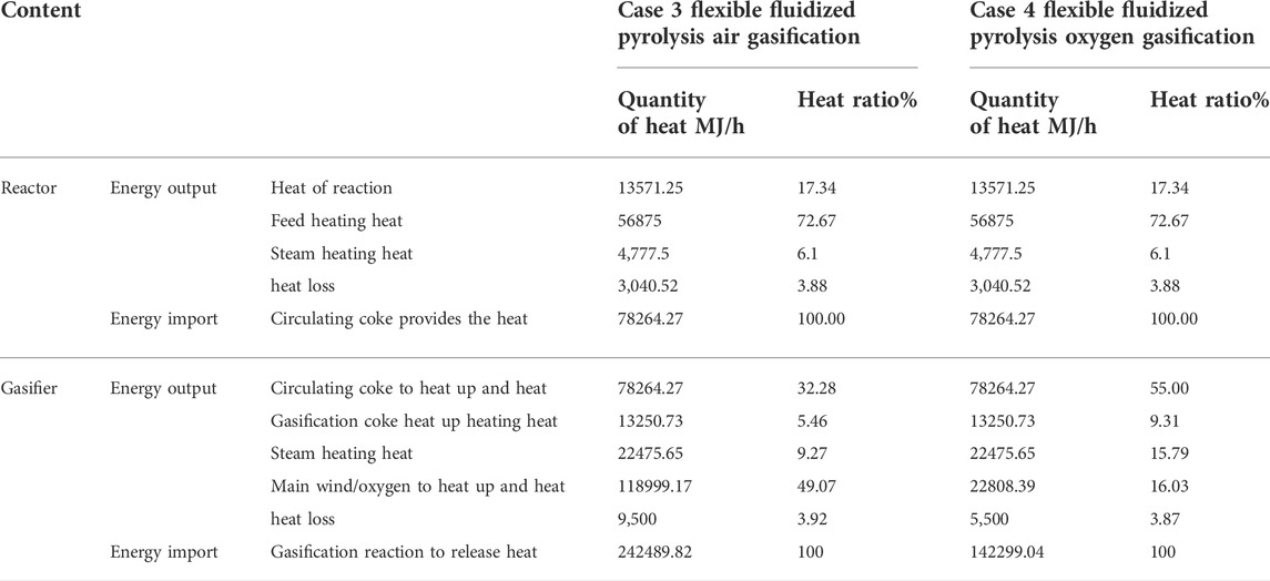
TABLE 5. Heat balance of the flexible fluidized pyrolysis process of the coal liquefaction residue.
For the flexible fluidized pyrolysis oxygen gasification process Case 4, when the gasifying agent air in Case 3 is replaced with oxygen, it can be seen that the temperature rise heat of oxygen in the main air has decreased to 19.16% and its proportion has also decreased to 16.03%. At this time, the temperature rise heat of circulating coke and gasification coke accounts for 64.31% and returns to the dominant position. From the total heat release of the gasification reaction, it can be seen that the heat release required by oxygen gasification decreased by 41.32%, indicating that oxygen gasification has a very obvious effect on improving the heat utilization rate of the process.
3) Comparison of the main technical indexes of the four process schemes
The main technical indexes of the four process schemes for the coal liquefaction residue are shown in Table 6. From the amount of organic coke consumed in the reaction and the amount of remaining organic coke, it can be seen that for the fluidized pyrolysis scheme of partial combustion, the coke consumed in Case 1 and Case 2 reactions accounts for only 7.5% of the total amount of organic coke, which can meet the heat balance of the whole pyrolysis and coke burning system. Compared with Case 1, the coke consumption of Case 2 is reduced by 18% due to the use of oxygen coke burning. For the flexible fluidized pyrolysis schemes Case 3 and Case 4, the organic coke is completely gasified and only inorganic solids are discharged. After high-temperature heat treatment above 900°C, the discharged solid meets the requirements of environmental protection easily.
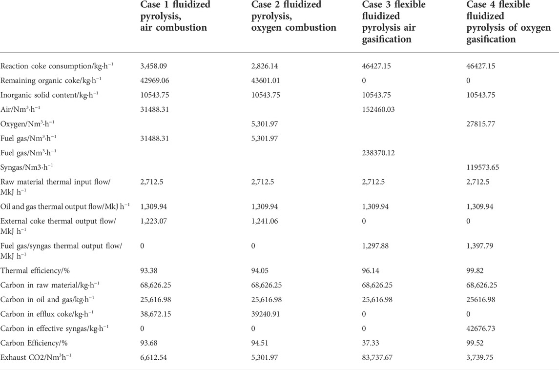
TABLE 6. Main technical indexes of the four processing schemes of the coal liquefaction residue.
For oxidants and gasifiers, the amount of main air or oxygen required by a fluidized pyrolysis scheme is much less than that of a flexible fluidized pyrolysis scheme. For the fluidized pyrolysis scheme, oxygen coke burning is adopted, and the gas volume is far less than that of air coke burning. The size of the coke burner and main air and fuel gas systems can be greatly reduced, which can significantly reduce the equipment investment. Moreover, the actual amount of oxygen in oxygen coking is also less than that in air coking, indicating that the heat required in the process decreases and the thermal efficiency improves. For flexible fluidized pyrolysis, the amount of main air or oxygen is nearly five times higher than that of fluidized pyrolysis, indicating that the size of the equipment will increase significantly. However, the granular coke produced by fluidized pyrolysis needs further treatment, and the coke produced by flexible fluidized pyrolysis can be transformed in situ. Therefore, the increased investment is meaningful. Compared with Case 3, the amount of the gasification agent in Case 4 is significantly reduced to 18%, and the equipment size can be significantly reduced.
For the thermal efficiency of the process, if the product contains coke and fuel gas/syngas, the chemical thermal efficiency of the four process schemes is higher, at 93–99%. In contrast, the flexible fluidized pyrolysis scheme is higher than the fluidized pyrolysis scheme, and the utility of oxygen as an oxidant or gasifier is higher than that of air as an oxidant or gasifier.
For carbon efficiency, in addition to the carbon entering the pyrolysis products in the fluidized pyrolysis process, a small part of the carbon is used as fuel for coke burning and generates CO2, and the rest of the carbon enters the coke products (granular coke is of little use and subsequent processing is difficult, so the direction of this part of carbon determines the total carbon efficiency). The total carbon efficiency is 93–94%. For the flexible fluidized pyrolysis process, if air is used as the gasification agent, coke gasification will make all the carbon in the coke generated by pyrolysis enter the fuel gas, which can only be burned as fuel and produce CO2 in the heating furnace. Therefore, the carbon efficiency of the flexible fluidized pyrolysis air gasification process in the calculation is very low, only 37.33%, and produces a large amount of CO2 emissions. In Case 4, because oxygen is used as a gasification agent, all the carbon in coke can enter syngas and be used as raw material for downstream chemical production. Therefore, the total carbon efficiency of this process reaches 99.52%, which is the highest among all processes and the lowest CO2 emissions. It can be seen that whether it is product scheme, thermal efficiency, or carbon efficiency, the flexible fluidized pyrolysis oxygen gasification scheme is the best scheme, which not only improves the process economy but also conforms to the China national environmental protection policy of energy conservation, emission reduction, and CO2 emission reduction.
Table 7 shows the composition of fuel gas for Case3 and Case4. It can be seen that the nitrogen content of fuel gas produced by Case 3 by using air as a gasification agent reaches 50.62 mol%, the low calorific value is only 5.4448 MJ/Nm3, and the molar ratio of H2/CO is 0.4560. It can only be used as fuel gas for factory heating furnaces. However, when oxygen is used as the gasification agent, as in Case 4, the generated synthesis gas contains almost no nitrogen, the low calorific value reaches 11.6898 MJ/Nm3, and the H2/CO molar ratio is 0.4432. After a certain amount of hydrogen is proportioned, the H2/CO is adjusted to the appropriate ratio, which can be used for syngas to methanol or syngas to olefin processes, which can produce high-value chemical products.
4) Flexible fluidized pyrolysis coupled with the water electrolysis process
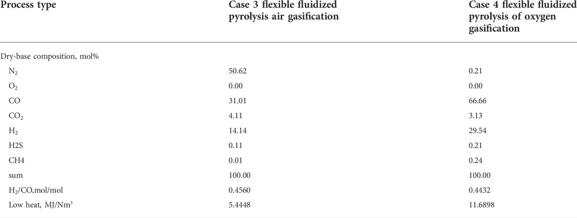
TABLE 7. Composition of fuel gas and syngas in the flexible fluidized pyrolysis process.
The comparative study of the abovementioned four schemes shows that the flexible fluidized pyrolysis process using oxygen as a gasification agent is the best choice, which can not only realize the complete transformation and utilization of organic matter in raw materials but also meet the heat balance of the unit. The carbon efficiency and thermal efficiency are close to 100%. For the oxygen required by this process, if it is produced through the traditional air separation device, the cost is greater. The production of oxygen itself requires energy consumption, so it will lead to a reduction in the energy efficiency of the whole plant. The coupling process of the flexible fluidized pyrolysis process with the water electrolysis process by solar energy is presented as shown in Figure 4. The source problem of oxygen in this scheme can be well-solved, and the green hydrogen produced by water electrolysis can be used to regulate the H2/CO of the syngas to meet the downstream chemical production requirements. This process scheme realizes the complete product utilization of organic matter in raw materials and the environmental protection standard discharge or comprehensive utilization of inorganic solids, and the heat required in the reaction is balanced by means of a small gasifier and its heat release. The oxygen required comes from the low-cost green oxygen byproduct of green hydrogen, and the syngas can be mixed with green hydrogen for chemical production. Syngas conversion into production chemicals, such as synthetic methanol in the process of water purification, can be used as a raw material for water electrolysis. Compared with the traditional fossil energy hydrogen production technology, hydrogen from water electrolysis production technology undergoes a simple process, no pollution, high hydrogen purity advantage, can be very good with renewable energy, and can also greatly reduce the cost of oxygen production from traditional air separation unit, so to become the final form of green hydrogen and green oxygen, the energy needed can come from solar or wind energy (Hu and Xu, 2022) (Yu et al., 2021) (dos Santos et al., 2017), which can realize the local coal conversion and utilization of solar energy.
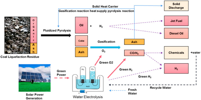
FIGURE 4. Coupling process of flexible fluidized pyrolysis of coal liquefaction residue with water electrolysis.
4 Conclusion and future work
In this study, the feed material characterization and fluidized bed pyrolysis experiments of the coal liquefaction residue were conducted. Aspen modeling and analysis of four fluidized pyrolysis processes were performed. The experiment and simulation results lead to the following conclusions:
1) The fluidized bed pyrolysis can be an effective process for CLR treatment. A C5+ oil yield of 34.81 wt% was obtained in the experiment for water and ash-free raw material basis. The best temperature distribution both in axial and radial directions in the fluidized bed reactor for the heat sensitive pyrolysis reaction is favorable to improving its oil yield as reaction temperature is the most crucial parameter for the pyrolysis process. There is an optimal value of 540°C for pyrolysis reaction temperature since the higher or lower value will lead to reduction of oil yield. In addition, the product coke is less likely to agglomerate than in the fixed-bed reactor due to the high-speed uniform dispersion and flow of the coke inside a fluidized bed. Based on the outcome of the present experimental study, the coke formation mechanism of fluidized bed pyrolysis should be further investigated.
2) The comparison results of four fluidized bed pyrolysis process simulation schemes indicate that the coal liquefaction residue can be converted into a clean product with the highest carbon efficiency (99.52%) for the proposed flexible fluidized bed pyrolysis coupled with water electrolysis. In this scheme, green O2 from water electrolysis is used for coke gasification for synthesis gas generation, and the green H2 can be used for adjusting the H2/CO ratio of the syngas, which can thus be used as feed gas for chemical production plants. This process can realize the energy balance between pyrolysis and gasification reactions, the complete organic matter utilization in raw materials, and nearly zero emission of CO2. All the carbon elements in coke are converted into syngas, which can be further utilized for chemical production, such as methanol or olefins.
3) Since the proposed flexible fluidized bed pyrolysis coupled with the water electrolysis can realize nearly zero CO2 emission in the CLR treatment process, it provides a new technical route for the CO2 emission reduction in organic solid waste utilization and other organic conversion processes, for instance, solid containing coal tar pyrolysis, refinery vacuum residue fluidized catalytic cracking (FCC), and fluidized coking (FC) process.
Data availability statement
The original contributions presented in the study are included in the article/Supplementary Material; further inquiries can be directed to the corresponding author.
Author contributions
BT is the author of the article; leads project research and technology development, engineering development and scale up. Bo processed research data and analytical data and process flow design, and performed Aspen simulations; JG, has contributed in reviewing the final article; QG has contributed in reviewing the final article. XZ, contributed in assisting wit experimen ts and analytical work; HZ, has contributed by assisting with experimental and analytical work; WZ, has contributed by assisting with experimental and analytical work; XH, has contributed by guiding the work; CY, has contributed in guiding the work and article; YY, has contributed in guiding and supervising the work; Y-WL, has contributed to guiding the work.
Conflict of interest
Authors BT, JG, QG, XZ, HZ, WZ, XH, YY, Y-WL, were employed by Synfuels China Technology Co., Ltd.
The remaining author declares that the research was conducted in the absence of any commercial or financial relationships that could be construed as a potential conflict of interest.
Publisher’s note
All claims expressed in this article are solely those of the authors and do not necessarily represent those of their affiliated organizations, or those of the publisher, the editors, and the reviewers. Any product that may be evaluated in this article, or claim that may be made by its manufacturer, is not guaranteed or endorsed by the publisher.
References
Cao, H., and Xiren, H. (2000). Calculation and Technical Analysis of Catalytic Cracking Process. Xi’an: Petroleum Industry Press, 10.
Chen, M., Yaohui, , Wang, H., and Chang, H. (2020). Exploration and Research on the Preparation of High Value-Added Products from Direct Coal Liquefaction Residues [J]. China coal. 46 (05), 74–80. doi:10.19880/j.cnki.ccm.2020.05.014
Cui, H., Yang, J., and Liu, Z. (1999). Investigation on the Basic Properties and Gasification Activity of Coal Liquefaction Residual Coke [J]. J. Fuel Chem. (S1), 16–20.
dos Santos, K. G., Eckert, C. T., De Rossi, E., Bariccatti, R. A., Frigo, E. P., Lindino, C. A., et al. (2017). Hydrogen Production in the Electrolysis of Water in Brazil, a Review. Renew. Sustain. Energy Rev. 68, 563–571. doi:10.1016/j.rser.2016.09.128
Hu, B., and Xu, L. (2022). Research Progress of PEM Electrolytic Water Hydrogen Production under Carbon Peak and Carbon Neutralization Target, Chemical Progress, 1–15 [2022-09-02]. doi:10.16085/j.issn.1000-6613.2021-2464
kun, G., Tian, Y., Xia, D., et al. (2011). Research Progress of Heavy Oil Catalytic Cracking Technology. Chem. Ind. Prog. 30 (6), 1219–1223.
Li, J., Yang, J., and Liu, Z. (2010). Research on the Pyrolysis Characteristics of Coal Direct Liquefied Residue. J. Fuel Chem. 38, 4.
Liu, B. (2012). Study on the Pyrolysis Characteristics of Direct Coal Liquefaction Residues. Northwestern University.
Shu, Geping (2009). Development Process and Significance of Shenhua Direct Coal Liquefaction Process [J]. Shenhua Sci. Technol. 7 (01), 78–82.
Tian, B., Yang, C., and Yang, Y. (2022). Research Progress on the Treatment Process of Direct Coal Liquefaction Residues [J]. Contemp. Chem. Industry Res. (09), 144–149.
Wang, Y., and Qi, J. (2012). Research Progress in Fluidized Coking Technology in China. Contemp. Chem. Ind. 41.
Winschel, R. A., and Burke, F. P. (1989). Recycle Oils from Fluid Coking of Coal Liquefaction Bottoms. Energy fuels. 3 (4), 437–443. doi:10.1021/ef00016a002
Xiang, Hongwei, Yang, Yong, and Li, Yongwang (2014). Indirect Coal Liquefaction: From Basic to Industrialization [J]. China Sci. Chem. 44 (12), 1876–1892.
Xiang, H., Yang, Y., and Li, A. (2022). Coal Chemical Industry Reform and Development. Chem. Prog. 41, 2022.
Xu, Long, Tang, Mingchen, Duan, Line, Liu, Baolin, Ma, Xiaoxun, Zhang, Yulong, et al. (2014). Pyrolysis Characteristics and Kinetics of Residue from China Shenhua Industrial Direct Coal Liquefaction Plant. Thermochim. Acta, 1–10. doi:10.1016/j.tca.2014.05.005
Yang, C., Chen, X., Li, C., and Shan, H. (2017). Challenges and Opportunities for Catalytic Cracking Technology. J. China Univ. Petroleum Nat. Sci. Ed. 41 (6), 171177.
Yang, Y., Tian, B., Gao, J., Zhu, X., Guo, Q., and Li, Y. (2020). A Continuous Treatment Method Containing Solid Slurry and a Device Used for the Implementation of This Method, CN112048339A
Yang, Yong, Xu, Jian, Liu, Zhenyu, Guo, Qinghua, Ye, Mao, Wang, Gang, et al. (2020). Progress in Coal Chemical Technologies of China. Rev. Chem. Eng. 36 (1), 21–66. doi:10.1515/revce-2017-0026
Yu, H., Shao, Z., Hou, M., Yi, B., Duan, F., and Yang, Y. (2021). Hydrogen Production by Water Electrolysis: Progress and Suggestions. Chin. J. Eng. Sci. 23 (2), 146. doi:10.15302/j-sscae-2021.02.020
Keywords: direct coal liquefaction, coal liquefaction residue, fluidized bed pyrolysis, flexi-fluid pyrolysis, carbon emission reduction, energy analysis, process simulation
Citation: Tian B, Gao J, Guo Q, Zhu X, Zhang H, Zhu W, Hao X, Yang C, Yang Y and Li Y-W (2022) Process study and CO2 emission reduction analysis of coal liquefaction residue fluidized bed pyrolysis. Front. Energy Res. 10:965047. doi: 10.3389/fenrg.2022.965047
Received: 09 June 2022; Accepted: 04 August 2022;
Published: 20 September 2022.
Edited by:
Nallapaneni Manoj Kumar, City University of Hong Kong, Hong Kong SAR, ChinaReviewed by:
Puranjan Mishra, Hong Kong Baptist University, Hong Kong SAR, ChinaAnshu Priya, City University of Hong Kong, Hong Kong SAR, China
Idiano D'Adamo, Sapienza University of Rome, Italy
Copyright © 2022 Tian, Gao, Guo, Zhu, Zhang, Zhu, Hao, Yang, Yang and Li. This is an open-access article distributed under the terms of the Creative Commons Attribution License (CC BY). The use, distribution or reproduction in other forums is permitted, provided the original author(s) and the copyright owner(s) are credited and that the original publication in this journal is cited, in accordance with accepted academic practice. No use, distribution or reproduction is permitted which does not comply with these terms.
*Correspondence: Bo Tian, dGlhbmJvQHN5bmZ1ZWxzY2hpbmEuY29tLmNu