
95% of researchers rate our articles as excellent or good
Learn more about the work of our research integrity team to safeguard the quality of each article we publish.
Find out more
ORIGINAL RESEARCH article
Front. Energy Res. , 04 August 2022
Sec. Smart Grids
Volume 10 - 2022 | https://doi.org/10.3389/fenrg.2022.964485
This article is part of the Research Topic Evolutionary Multi-Objective Optimization Algorithms in Microgrid Power Dispatching View all 16 articles
Large-scale photovoltaic (PV) generation grid connection causes lack of inertia and insufficient frequency regulation capacity of power system. To solve this problem, this study proposed the active power-frequency droop control (APFDC) and virtual inertia control (VIC) for single-stage PV generation. PV generation is able to participate in the grid frequency regulation by improving the control system of voltage source converter (VSC). The effect of control parameters on the inertia characteristic of PV generation is analyzed. On this basis, the distribution mechanism of unbalanced active power among PV generators with inertia control strategy is revealed. The simulation results indicated that PV generation can be controlled by setting the control strategy of the voltage source converter (VSC) to reduce or increase the active power; it also takes part in the frequency regulation of the system. The inertia provided by PV generation is controllable and frequency-dependent, increases with the increase in control gain, the decrease in the time constant of VIC, and the decrease in phase-locked loop (PLL) control bandwidth.
The development of photovoltaic (PV) generation is an important means to deal with the current severe environmental problems and global energy transformation. At the end of 2020, the installed capacity of grid-connected PV generation in China has reached 253 million kW, indicating a year-on-year increase of 24.1%. It is estimated that by the end of 2030 and 2050, this value will reach 1,500 million and 2,700 million kW, respectively.
PV generation unit is connected to the power grid through power electronic converters. Large-scale PV generation grid connection weakens the system inertia, reduces the system ability of frequency regulation, and seriously endangers system frequency security and stability (Pedro et al., 2016; Jesus et al., 2017; Fang et al., 2019). Some countries and regions have issued requirements and technical guidelines, which require PV plants to have the ability to respond to system frequency changes (Datta et al., 2011; Liu et al., 2014; Jibji-bukar and Anaya-lara, 2019). Field test on PV generation participating in primary frequency control was conducted by the State Grid Corporation of China (Xiaoqiang et al., 2017; Xiaoqiang et al., 2018).
A novel power point track method was proposed by Pappu et al. (2010), which is used for frequency stabilization and active power reserves. In the frequency dynamic process, the reloading algorithm is activated by the control sign; the algorithm uses a modified fractional open-circuit voltage (Mohammad et al., 2017). A power point tracking method based on Lagrange quadratic interpolation method was proposed by Yun et al. (2012) and Huanhai et al. (2013), according to the relationship of the maximum output power and output demand of PV array, related to the relationship between the maximum output power and output PV array demand, PV generation can choose between two modes (constant power output mode and MPPT mode) automatically. Zarina et al. (2014) proposed a frequency regulation method by improving the DC voltage control loop of the inverter. The method illustrates frequency regulation by establishing the proportional integral relationship between the grid frequency deviation Δf and the output DC voltage deviation ΔUdc. Nevertheless, how to establish the proportional integral relationship between Δf and ΔUdc is still unanswered.
In the research from “A control strategy for photovoltaic generation system based on quadratic interpolation method.” (Yun et al., 2012) and “A new frequency regulation strategy for photovoltaic systems without energy storage” (Huanhai et al., 2013) and “Exploring frequency control capability of a PV system in a hybrid PV-rotating machine-without storage system.” (Zarina et al., 2014), the DC voltage controller of VSC plays one of the key roles of actualizing participation in the grid frequency modulation of PV generation. The reference value of the DC capacitor voltage can be adjusted using the grid frequency deviation Δf so PV generation can participate in frequency regulation. However, it is not easy to set initial reference of the DC capacitor voltage because of the randomness of illumination and the nonlinear relationship between the DC capacitor voltage and PV array output active power. PV generation participating in frequency modulation is strictly limited by the aforementioned relationship between Δf and ΔUdc. Furthermore, how to evaluate the inertia characteristics of PV generation is rarely studied.
In the study of the frequency characteristics of system with PV generation, the relationship between the output active power of PV generation and grid frequency has gained a considerable amount of attention. Therefore, a model that accurately describes the characteristics of PV generation electromechanical transient serves as the basis for on-grid analysis. At present, America’s WECC and China’s GB/T 32,826–2016 “Guide for modeling photovoltaic power system” have proposed a general PV generation model for electromechanical transient analysis (WECC Renewable Energy Modeling Task Force, 2012; Lei et al., 2015; SPC, 2016). (Linan et al., 2018) combined with the measured data for the manual short-circuit test of a PV power station in Northwest China, effectively verified the proposed model is “verified the electromechanical transient model of PV generation.” Unlike the electromagnetic transient model, the electromechanical transient model ignores numerous processes, such as PWM modulation and coordinate transformation, and replaces its DC voltage controller with active power controller (Nanou and Papathanassiou, 2014). Because of the differences between the two model control systems, there is discrepancy in designed control strategies (Sangwongwanich et al., 2017; Lyu et al., 2018).
This study proposed the virtual inertia control (VIC) strategy and the active power-frequency droop control strategy (APFDC) based on the single-stage PV generation electromechanical transient model, evaluating the inertia characteristics of PV generation. The contributions of this study are as follows:
1) The control system of VSC was improved so that PV generation actively participates in the system frequency regulation.
2) According to the relationship between unbalanced active power from the system and phase output of internal voltage, the effect of the PLL control bandwidth, control gain, and time constant on the PV generation inertia characteristics is discussed, and the effect of the PV generation inertia on frequency dynamics is analyzed.
3) The dynamic power distribution mechanism of PV generation units with VIC is revealed.
The structure of this article is arranged as follows: the configuration of single-stage grid-connected PV generation is investigated in Section 2. The electromechanical transient model of VSC is proposed in Section 3. In Section 4, the frequency regulation control strategies, including APFDC and VIC, are presented. Section 5 discusses the inertia characteristics of PV generation. The simulation results are presented in Section 6 and the conclusions in Section 7.
The structure of grid-connected single-stage PV generation is presented in Figure 1. The figure shows the main parts of the system, including the PV array, voltage source converter (VSC), and AC grid. The output active power of the PV array can be delivered to the grid side through the VSC (Yu et al., 2018). C is the DC filter capacitor, Udc is the DC-side voltage of the PV array, Lf is the filter inductance, Ut is the voltage of point of common coupling (PCC), Lg is the inductance, Rg is the resistance of the transmission line, Pload is the load, and Ug is the grid side voltage.
The configuration of the PV array is presented in Figure 2, in which Ns and Np represent the number of series and parallel connected cells. The Udc-IPV characteristic of a PV array from manufacturer is shown in (1).
Here, IPV is the DC current, Isc and Uoc are the short-circuit current and open-circuit voltage, respectively; C1 and C2 are coefficients obtained in (2).
Here, Im and Um represent the maximum current and voltage, respectively, when the PV array operates at the maximum power point.
The relationship of PPV and Udc is obtained in (3) based on (1).
The transcendental equation in (3) adds many difficulties to the modeling of PV array. Thus, Lei et al. (2015) proposed a simplified output active power model of PV array, which is expressed in (4).
where Sref is the rating irradiance, b is the constant associated with the material of battery (typical reference value b = 0.0005 m2/W), and e is the Euler number.
The active power reserves ΔP of PV generation if operating in the limited power mode (σ% is the active power reserve ratio) is expressed in (5).
The electromagnetic transient model of VSC is shown in Supplementary Figure SA1 of Supplementary Appendix SA, and a typical vector control strategy is shown in Supplementary Figure SA2 of Supplementary Appendix SA. In the electromagnetic transient control system of VSC, it contains the current controllers, PWM modulation, etc. However, the response speed of these modules is in millisecond, and the dynamic process of rapid response can be neglected while analyzing the electromechanical transient problems.
To accurately describe the electromechanical transient characteristics of VSC, Linan et al. (2018) established an electromechanical transient model of VSC. Figure 3 shows the VSC equivalent model, where S is the illumination; Pn is the maximum active power of PV array under the current illumination; Pcmd and Qcmd represent the reference of active and reactive powers, respectively; PPV and QPV represent the actual values of active and reactive power; and utem is the PCC voltage.
Supplementary Figure SA3 of Supplementary Appendix SA shows the specific control structure of active and reactive power control modules. Compared with the electromagnetic transient control system of VSC, the active power control replaces the DC voltage control in the electromechanical transient control system of VSC; however, this part will not be described in detail. The PV generation frequency support control strategy will pay more attention to the electromechanical transient model of VSC and its control system in the next part (Varma et al., 2015; Batzelis et al., 2017).
In this section, the active power-frequency droop characteristic curve of PV generation is presented in Figure 4 and the corresponding mathematical expression in (6).
where fd is the system frequency response value of VSC, Pn is the maximum active power output of PV generation under the current illumination, k is the frequency adjustment coefficient in 1/Hz, and P0 is the initial output active power of PV generation.
Figure 5 shows the modified control system of VSC, where PV generation is operated under limited power mode. The output active power of PV generation (P0) when the grid frequency f is stable is PPV*(1-σ%). When power disturbance occurs in the system, f is sent to the droop control loop and generates the output active power reference PPVref (Firdaus and Mishra, 2019). The d-axis current reference value idref of VSC is generated by comparing the differences between PPVref and P in active power controller.
As can be seen from Supplementary Figure SA2 of Supplementary Appendix SA, the function of the phase-locked loop (PLL) is to align the d-axis frame with the PCC voltage Ut. Supplementary Figure SA4 of Supplementary Appendix SA shows the control system of the PLL (Panda et al., 2019).
According to the control strategy of the PLL, the relationship of f and the PLL is shown in (7); (8) obtains the active power increment ΔPPV of VIC, which makes VIC based on the dynamics of PLL achieved.
where Utq is the PCC voltage in the q-axis, kp4 and ki4 are the PLL parameters, and HPV is the time constant of VIC.
Figure 6 presents the relationship of ΔPPV, HPV, and Utq with the fixed integral coefficient of PLL. Figure 6 demonstrates that as the HPV and Utq increase, the PV will generate more active power.
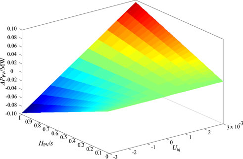
FIGURE 6. The relationship of ΔPPV, HPV, and Utq with the fixed integral coefficient of PLL (ki4 = 100)
In general, APFDC and VIC are combined to participate in frequency regulation; the control strategies are shown in Figure 7. When active power disturbances occur in the system, the grid frequency disturbance f is delivered to the VIC link (a low-pass filter is introduced to the inertia control link; K1 and T1 are the control gain and the filter time constant, respectively), and the APFDC link can generate the power reference value because of the detection by the PLL (Anderson and Mirheydar, 1990; Ma et al., 2021a).
Based on the relationship of VSC (Kakimoto et al., 2009; Fazeli et al., 2014), the inertia characteristics of PV generation with different control parameters will be further analyzed (Moradi-shahrbabak et al., 2018; Wu et al., 2018; Ma et al., 2021b). The linearization relationship of the unbalanced active power excitation–phase output response of the VSC is shown in Figure 8A (the influence of reactive power control on active power control is ignored). In Figure 8A, ΔPin is the PV array output power disturbance, ΔPPV is the VSC output power disturbance, Δθt is the PCC voltage phase disturbance, Δθpll is the PLL output phase disturbance, Δθ is the internal phase disturbance in VSC, and E0 and Ut0 are the initial of the internal voltage of VSC and the initial of PCC voltage, respectively (Yuan et al., 2017; Ma et al., 2021c).
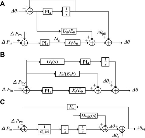
FIGURE 8. The unbalanced active power excitation–phase output response of VSC. (A) Block diagram of PV generation inner electric potential phase dynamic. (B) Block diagram of replaced PV generation voltage phase. (C) Block diagram of PV generation including equivalent inertia and damping coefficient.
The expression of PV generation output power and internal potential as well as the PCC voltage are presented in (9); replacing the Δθt in Figure 8A with the linearization result of (9). The relationship between the unbalanced active power excitation and the phase output response of VSC can be further simplified as in Figures 8B, C, where G1(s) is expressed in (10).
In Figure 8C, GM(s) is the equivalent inertia of PV generation, and DVSC(s) is the equivalent damping coefficient. GM(s) and DVSC(s) are related to system structure parameters and operating conditions; their expressions are presented in Supplementary Appendix SA. Furthermore, the unbalanced active power excitation–phase output response relationship indicates how power disturbance influences the movements of E by the inertia and damping coefficient (Ma et al., 2021d) and also how coefficients are determined by the operating points and control parameters of PV generation.
Considering the relationship between the rate of range of frequency (ROCOF) and Utq, the linearization result is shown in (11). When the VIC strategy is adopted in PV generation, its unbalanced active power excitation–phase output response is shown in Figure 9A and further simplified in Figures 9B, C, D.
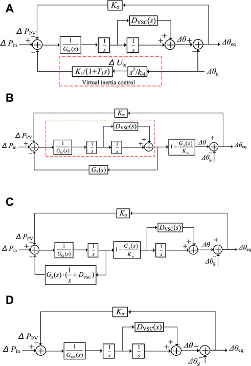
FIGURE 9. The unbalanced active power excitation–phase output response of VSC based on the virtual inertia control strategy. (A) Block diagram of PV generation inner electric potential phase dynamic. (B) Organized block diagram of PV generation inner electric potential phase dynamic. (C) Block diagram of input active power-output inner electric potential phase. (D) Block diagram of PV generation including equivalent inertia and damping coefficient.
In Figure 9D, its equivalent inertia GM1(s) is shown in (12). Based on (12), Figure 10 shows the Bode diagrams of GM1(s), which are obtained under different control gain coefficients K1, different time constants T1, and different PLL control bandwidths (Sangwongwanich et al., 2018). Figure 10shows that 1) the equivalent inertia of PV generation is frequency-dependent and controllable, different from the constant inertia of SG, and 2) with the increase in the control gain coefficient K1 (1–30), decrease in the time constant T1 (30–1), or decrease in the control bandwidth (9.99–3.65 Hz) of PLL, a larger inertia can be provided by PV generation in the dynamic process of grid frequency.
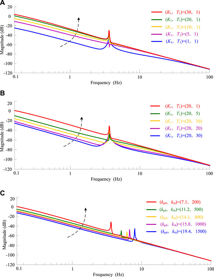
FIGURE 10. The inertia characteristics of PV generation. (A) Control gain coefficient variation. (B) Time constant variation. (C) PLL control bandwidths variation.
Figure 11 shows the synchronous frequency regulation (SFR) model of SG (Linan et al., 2018). In Figure 11, TJ is the inertia time constant of SG, Dg is the equivalent damping coefficient of SG, R is the adjustment coefficient of speed regulator, TR is the prime mover reheat time constant, FH is the fraction of total power generated by the HP turbine, Km is the mechanical power gain factor, Psp is the incremental power set point, PL2 is the load power, and Δωg is the inner frequency of the internal voltage of SG.
Based on the unbalanced power excitation–phase output relation in Figure 9 and the SFR model of SG in Figure 11, it can be observed that
where ΔωPV is the inner frequency of PV generation of internal voltage.
If Δωg = ΔωPV, by combining (13) and (15), Δωg can be expressed as follows:
In this method, we give a considerable amount of attention to ΔPL in the form of a step function, ΔPL = ΔPs/s. Thus,
According to the final value theorem, we can obtain the initial ROCOF and steady-state frequency error of the system as follows:
It can be seen from (17), (18), and (19) that PV generation with VIC does not affect the initial rate of change and steady-state deviation of the grid frequency (Yazdani et al., 2011; Sangwongwanich et al., 2018). However, during the dynamic of grid frequency means the dynamic characteristics of the grid frequency, PV generation plays a vital role, depending on its inertia. It can effectively restrain the drop of the lowest frequency point (or the rise of the highest frequency point) and the ROCOF under different control parameters.
When PV generation units adopt the VIC, the dynamic power distribution mechanism of PV units is further discussed based on the unbalanced active power excitation–phase output response of VSC (Hydro Quebec TransÉnergie, 2009; Khazaei et al., 2020). The structure of two paralleled PV units is shown in Figure 12. In Figure 12, E1 and E2 are the magnitudes of the internal voltage vector; θ1 and θ2 are the phases of the internal voltage vector; E′ and θ’ are the magnitude and the phase of the PCC voltage vector, respectively; Xf1 and Xf2 are the output filter reactance; Xc1 and Xc2 are the reactance of each PV generation to the interconnection point; and Xg is the transmission line reactance.
The output power of each PV generation is shown in (20), linearizing (20) (neglect the effect of voltage magnitude disturbance), and the phase θ’ of the PCC voltage vector can be obtained using (21).
where X is the total reactance.
Combining (21) and Figure 9D, the unbalanced active power excitation–phase output response of two paralleled PV generation units with the inertia control strategy is shown in Figure 13A and the simplified relationship in Figure 13B, where the derivation and expression of G11(s) and G12(s) are given in Supplementary Appendix SB; D11(s) and D12(s) are the power distribution coefficients.
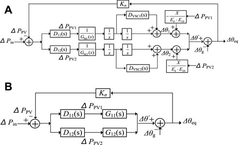
FIGURE 13. The unbalanced active power excitation–phase output response of two paralleled PV generation units based on the virtual inertia control strategy. (A) Block diagram of two parallel PV generation units. (B) Simplified block diagram of two parallel PV generation units.
According to Figure 13B, the phase θ’ of the PCC voltage vector is also shown in (22), and the dynamic power distribution coefficients D11(s) and D12(s) are shown in (23) and (24).
From (24), it can be seen that the dynamic power distribution coefficients depend on the inertia characteristics of PV generation units. Therefore, the dynamic power distribution mechanisms are similar to those of conventional synchronous generators (ENTSO -E, 2013), which is helpful in understanding the dynamic process of PV generation units with inertia control strategy.
Figure 14 presents the Bode diagrams of D11(s) and D12(s) with different control parameters. We can see from Figure 14 that with the increase in control gain, decrease in the time constant of VIC, and decrease in the PLL control bandwidth, the power distribution coefficient of PV generation in the low-frequency band will also increase, indicating that PV generation provided a more active power during active power disturbance.
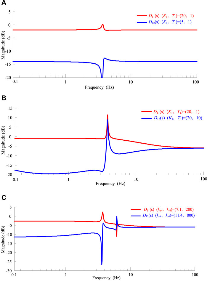
FIGURE 14. The Bode diagrams of D11(s) and D12(s) with different control parameters. (A) Control gain coefficient variation. (B) Time constant variation. (C) PLL control bandwidths variation.
A simulation model was built in PSCAD/EMTDC to verify the above theory analysis, as shown in Figure 15. Table 1 presents the main parameters of the single-stage PV system; the PV power plant is represented by a single equivalent model in the following simulations.
The background of the simulation is as follows: output active power of PV generation PPV = 600 MW (σ% = 20%), system load PL = 2000MW, and a load increased by 200-MW disturbance occurs at t = 40s. Figure 16 reflects the output power of synchronous unit 1 responses (PG1), the output power of PV generation responses (PPV) under different controls, and the grid frequency responses (f) during the disturbance.
The simulation results in Figure 16 indicated the following: 1) If PV units do not participate in the system frequency regulation, the system frequency will drop below 49.6 Hz; the ROCOF of the system is large. 2) If VIC is activated, the PV units will increase the active power by 100 MW immediately to contain the drop of frequency. However, when the system frequency tends to be stable, the PV output active power has the same value as in the first case, which means that VIC does not affect the steady-state frequency after the disturbance, only the transient-state process of system frequency. 3) If the APFDC is activated, the active power of the PV array is controlled by the VSC according to the active power-frequency droop curve shown in Figure 4. As a result, an 80-MW extra active power is added to inhibit the drop of frequency. After a dynamic process of about 20 s, the steady-state frequency of the system is about 49.85 Hz, which is higher than those in the former cases. 4) If both droop control and VIC are activated, PV generation will obviously improve the dynamic process characteristic by adding more active power. It not only increases the equivalent inertia of the system, which can constrain the ROCOF, but also reduces the frequency deviation.
The background of the simulation is as follows: output active power of PV generation PPV = 600 MW (σ% = 20%), system load PL = 2000 MW, and a load increased by 200-MW disturbance occurs at t = 40 s. When the low-pass filter controlled by the virtual inertia is constant (T1 = 1 s), the control gain of the low-pass filter is increased from 5 to 20. Figure 17A indicates that with the increase in control gain, the virtual inertia of PV generation gradually increases, the ROCOF of the system during the active power disturbance decreases, and the maximum frequency deviation decreases.
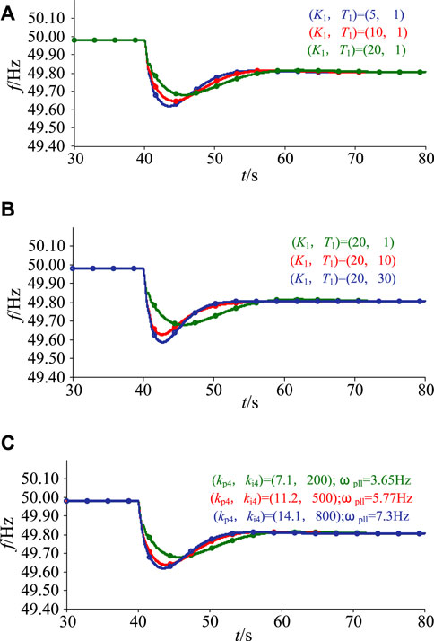
FIGURE 17. System operation curve with various control parameters. (A) control gain coefficient variation. (B) Time constant variation. (C) PLL control bandwidths variation.
When the control gain of the low-pass filter controlled by the virtual inertia is constant (K1 = 20), T1 is increased from 1 to 30. Figure 17B indicates that with the increase in time constant, the virtual inertia of PV generation gradually decreases, the ROCOF of the system during the active power disturbance increases, and the maximum frequency deviation increases.
Figure 17C shows the grid frequency responses at different PLL control parameters of the VSC. According to Figure 17C, with the increase in the PLL bandwidth (ωPLL = 3.65–7.3 Hz), the equivalent inertia of PV generation decreases, the ROCOF of the system during the active power disturbance increases, and the maximum frequency deviation increases.
Taken together, with the increase in control gain, more output active power can be produced in the PV generation, the ROCOF becomes smaller, and the maximum frequency deviation decreases.
The PV power station consist of two PV generation units, as shown in Figure 18, the rated active output power of each PV generation unit is 400 MW (=10%), the load of the system is 2000 MW, a disturbance with 200 MW load increase occurred at t = 40 s. Figure 18 shows the active power of PV array responses (Pin1 and Pin2) and the output power of PV generation unit responses (PPV1 and PPV2) under different control parameters.
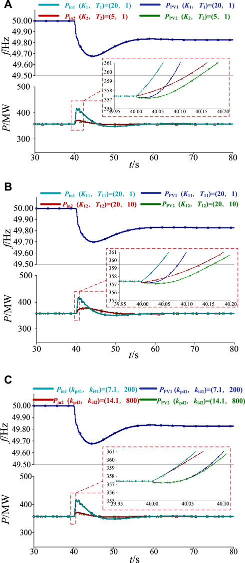
FIGURE 18. The system responses for PV generation units under different control parameters. (A) control gain coefficient variation. (B) Time constant variation. (C) PLL control bandwidths variation.
The difference between the input and output active powers of the PV array represents the unbalanced power borne by the PV generation unit. Figure 18 shows that when the control gain K1 of PV generation unit 1 is greater than K2 of PV generation unit 2, the time constant T1 is smaller than the time constant T2, or the control bandwidth ωPLL1 of the PLL is smaller than ωPLL2, the equivalent inertia GM1(s) of PV generation unit 1 is greater than GM2(s) of PV generation unit 2, the corresponding unbalanced power distribution coefficient D11(s) is greater than D12(s), and the unbalanced power borne by PV generation unit 1 is greater than the unbalanced power borne by PV generation unit 2 during the dynamic of grid frequency.
In the actual grid operation scenarios, the proposed PV generation frequency regulation strategy has proven effective. The simulation was performed under the condition of variable irradiance and load. Figure 19 presents the grid frequency responses under the variable load, and Figure 20 shows the normal distribution of grid frequency. Figure 21 presents the grid frequency responses under variable irradiance, and Figure 22 shows the normal distribution of grid frequency. We can see from Figures 19–22, we can conclude that when PV generation participates the frequency regulation, under this condition, the frequency fluctuation is inhibited as well as enhances the grid frequency stability based on the pre-set APFDC strategy and VIC strategy.
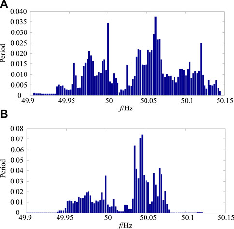
FIGURE 20. Normal distribution of grid frequency: (A) no frequency regulation, (B) frequency regulation.
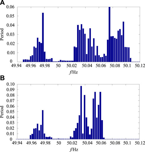
FIGURE 22. Normal distribution of grid frequency: (A) no frequency regulation, (B) frequency regulation.
In this study, the single-stage PV generation frequency regulation strategies are proposed, including VIC and droop control, based on the electromechanical transient model. The method proposed in this study is to realize that the control strategies modify the VSC control system. The effect of the control parameters on the inertia characteristics is analyzed. Furthermore, the dynamic power distribution mechanism of PV generation units with the inertia control strategy is revealed, and the following conclusions were drawn:
1) The PV generation can decrease or increase the output active power controlled by VSC based on the PV generation frequency regulation strategies, thus improving the frequency stability of the system. PV generation can increase (or decrease) the output active power to respond to the changes in the system frequency when active power disturbances occur in the system according to the pre-set droop curve.
2) Different from the synchronous unit (SG), the inertia provided by PV generation with VIC is controllable and depends on the grid frequency. With the increase in the gain, decrease in the time constant of the VIC, and decrease in the control bandwidth of PLL, more inertia will be provided by PV generation.
3) The dynamic power distribution mechanisms of PV generation units with the VIC strategy are similar to those of conventional synchronous generators, which depend on the inertia characteristics of PV generation units. With the increase in the gain, decrease in the time constant of the VIC, and decrease in the control bandwidth of PLL, the active power distribution coefficient of PV generation in the low-frequency band will also increase, and thus, more active power can be provided to constrain the changes in the grid frequency.
The raw data supporting the conclusion of this article will be made available by the authors, without undue reservation.
XF: research paper writing, research paper structure design, simulation model design. XW: research paper writing, literature review. QJ: simulation model design. HW: research paper writing.
The authors declare that the research was conducted in the absence of any commercial or financial relationships that could be construed as a potential conflict of interest.
All claims expressed in this article are solely those of the authors and do not necessarily represent those of their affiliated organizations, or those of the publisher, the editors, and the reviewers. Any product that may be evaluated in this article, or claim that may be made by its manufacturer, is not guaranteed or endorsed by the publisher.
The Supplementary Material for this article can be found online at: https://www.frontiersin.org/articles/10.3389/fenrg.2022.964485/full#supplementary-material
Anderson, P., M., and Mirheydar, M. (1990). A low-order system frequency response model. IEEE Trans. Power Syst. 5 (3), 720–729. doi:10.1109/59.65898
Batzelis, E. I., Kampitsis, G. E., Papathanassiou, S. A., and Member, S. (2017). Power reserves control for PV systems with real-time MPP estimation via curve fitting. IEEE Trans. Sustain. Energy 8 (3), 1269–1280. doi:10.1109/tste.2017.2674693
Datta, M., Member, S., Senjyu, T., Member, S., and Yona, A. (2011). A frequency-control approach by photovoltaic generator in a PV – diesel hybrid power system. IEEE Trans. Energy Convers. 26 (2), 559–571. doi:10.1109/tec.2010.2089688
ENTSO-E (2013). ENTSO-E: Network code for requirements for grid connection applicable to all generators (nc rfg). Brussels: Entsoe.
Fang, J., Li, H., Tang, Y., and Blaabjerg, F. (2019). On the inertia of future more-electronics power systems. IEEE J. Emerg. Sel. Top. Power Electron. 7 (4), 2130–2146. doi:10.1109/jestpe.2018.2877766
Fazeli, M., Ekanayake, J. B., Member, S., and Holland, P. M. (2014). Exploiting PV inverters to support local voltage. A Small-Signal Model 29 (2), 453–462. doi:10.1109/TEC.2014.2300012
Firdaus, A., and Mishra, S. (2019). Auxiliary signal-assisted droop-based secondary frequency control of inverter- based PV microgrids for improvement in power sharing and system stability. IET Renew. Power Gener. 13, 2328. doi:10.1049/iet-rpg.2018.6171
Huanhai, X., Yun, L., Zhen, W., Gan, D., and Yang, T. (2013). A new frequency regulation strategy for photovoltaic systems without energy storage. IEEE Trans. Sustain. Energy 4 (4), 985–993. doi:10.1109/tste.2013.2261567
Hydro Quebec TransÉnergie (2009). Transmission provider technical requirements for the connection of power plants to the hydro-Québec transmission system. Canada: Hydro Quebec TransÉnergie, Montréal, QC.
Jesus, C., H., Pedro, G., B., and Francisco, S. (2017). Enhanced utility-scale photovoltaic units with frequency support functions and dynamic grid support for transmission systems. IET Renew. Power Gener. 11 (3), 361–372. doi:10.1049/iet-rpg.2016.0714
Jibji-bukar, F., and Anaya-lara, O. (2019). Frequency support from photovoltaic power plants using offline maximum power point tracking and variable droop control. IET Renew. Power Gener. 13, 2278. doi:10.1049/iet-rpg.2019.0211
Kakimoto, N., Takayama, S., Satoh, H., and Nakamura, K. (2009). Power modulation of photovoltaic generator for frequency control of power system. IEEE Trans. Energy Convers. 24 (4), 943–949. doi:10.1109/tec.2009.2026616
Khazaei, J., Tu, Z., Member, S., Liu, W., and Member, S. (2020). Small-Signal modeling and analysis of virtual inertia-based PV systems. IEEE Trans. Energy Convers. 35 (2), 1129–1138. doi:10.1109/TEC.2020.2973102
Lei, Z., Lingzhi, Z., Ning, C., Zhao, D., and Qu, L. (2015). Review on generic model for renewable energy generation. Automation Electr. Power Syst. 39 (24), 129–138. doi:10.7500/AEPS20150629010
Linan, Q., Luming, G., Lingzhi, Z., Shuanbao, N., Shuang, Z., and Sijia, B. (2018). Transient modeling of photovoltaic power plant and its test validation. Automation Electr. Power Syst. 42 (10), 170–175.
Liu, Y., Xin, H., Wang, Z., and Yang, T. (2014). Power control strategy for photovoltaic system based on the Newton quadratic interpolation. IET Renew. Power Gener. 8, 611–620. doi:10.1049/iet-rpg.2013.0067
Lyu, X., Xu, Z., Zhao, J., and Wong, K. P. (2018). Advanced frequency support strategy of photovoltaic system considering changing working conditions. IET Gener. Transm. &. Distrib. 12, 363–370. doi:10.1049/iet-gtd.2017.0700
Ma, L., Wang, X., Wang, X., Wang, L., Shi, L., Huang, M., et al. (2021a). TCDA: Truthful combinatorial double auctions for mobile edge computing in industrial internet of things. IEEE Trans. Mob. Comput., 1. doi:10.1109/TMC.2021.3064314
Ma, L., Huang, M., Yang, S., Wang, R., and Wang, X. (2021c). An adaptive localized decision variable analysis approach to large-scale multiobjective and many-objective optimization. IEEE Trans. Cybern. PP(99), 1–13. doi:10.1109/TCYB.2020.3041212
Ma, Lianbo., Cheng, Shi, and Shi, Yuhui (2021b). Enhancing learning efficiency of brain storm optimization via orthogonal learning design. IEEE Trans. Syst. Man. Cybern. Syst. 51 (11), 6723–6742, Nov. doi:10.1109/tsmc.2020.2963943
Ma, Lianbo, Li, Nan, Guo, Yinan, Huang, Min, Yang, Shengxiang, Wang, Xingwei, et al. (2021d). Learning to optimize: Reference vector reinforcement learning adaption to constrained many-objective optimization of industrial copper burdening system. IEEE Trans. Cybern., 1–14. doi:10.1109/TCYB.2021.3086501
Mohammad, D., Mokhlis, H., and Saad, M. (2017). Inertia response and frequency control techniques for renewable energy sources: A review. Renew. Sustain. Energy Rev. 69, 144–155. doi:10.1016/j.rser.2016.11.170
Moradi-shahrbabak, Z., Member, S., and Tabesh, A. (2018). Effects of front-end converter and DC-link of a utility-scale PV energy system on dynamic stability of a power system. IEEE Trans. Ind. Electron. 65 (1), 403–411. doi:10.1109/tie.2017.2721902
Nanou, S. I., and Papathanassiou, S. A. (2014). Modeling of a PV system with grid code compatibility. Electr. Power Syst. Res. 116, 301–310. doi:10.1016/j.epsr.2014.06.021
Panda, R. K., Mohapatra, A., and Srivastava, S. C. (2019). Enhancing inertia of solar photovoltaic-based microgrid through notch filter-based PLL in SRF control. IET Renew. Power Gener. 14, 379. doi:10.1049/iet-gtd.2018.7058
Pappu, V., Chowdhury, B., and Bhatt, R. (2010). “Implementing frequency regulation capability in a solar photovoltaic power plant,” in Proceeding of North American Power Symposium Conference, Arlington, TX, USA, 26-28 September 2010 (NAPS), 1–6.
Pedro, G., B., Jesus, C., H., and Francisco, J., R. (2016). Stability assessment for transmission systems with large utility-scale photovoltaic units. IET Renew. Power Gener. 10 (5), 584–597. doi:10.1049/iet-rpg.2015.0331
Sangwongwanich, A., Yang, Y., Blaabjerg, F., and Sera, D. (2017). Delta power control strategy for MultistringGrid-connected PV inverters. IEEE Trans. Industry Appl. 53 (4), 3862–3870. doi:10.1109/TIA.2017.2681044[
Sangwongwanich, A., Member, S., and Yang, Y. (2018). Benchmarking of constant power generation strategies for single-phase grid-connected photovoltaic systems. IEEE Trans. Industry Appl. 54 (1), 447–457. doi:10.1109/TIA.2017.2740380
SPC (2016). Guide for modeling photovoltaic power system: GB/T 32826-2016. Beijing: Standards Press of China.
Varma, R. K., Member, S., Rahman, S. A., and Vanderheide, T. (2015). New control of PV solar farm as STATCOM (PV-STATCOM) for increasing grid power transmission limits during night and day. IEEE Trans. Power Deliv. 30 (2), 755–763. doi:10.1109/tpwrd.2014.2375216
WECC Renewable Energy Modeling Task Force (2012). Generic solar photovoltaic system dynamic simulation model specification.
Wu, Z., Gao, W., Gao, T., Yan, W., Zhang, H., Yan, S., et al. (2018). State-of-the-art review on frequency response of wind power plants in power systems. J. Mod. Power Syst. Clean. Energy 6 (1), 1–16. doi:10.1007/s40565-017-0315-y
Xiaoqiang, S., Song, C., Xin, L., Naixin, D., Yunlong, C., and Hua, L. (2018). Test method for frequency characteristics of Northwest sending-end power grid. Power Syst. Technol. 42 (2), 148–153.
Xiaoqiang, S., Min, G., Xin, L., Song, C., Naixin, D., Yunlong, C., et al. (2017). Actual measurement and analysis of fast frequency response capability of PV-inverters in Northwest power grid. Power Syst. Technol. 41 (9), 2792–2798.
Yazdani, A., Di Fazio, A. R., Ghoddami, H., Russo, M., and Kazerani, M. (2011). Modeling guidelines and a benchmark for power system simulation studies of three-phase single-stage photovoltaic systems. IEEE Trans. Power Deliv. 26 (2), 1247–1264. doi:10.1109/TPWRD.2010.2084599
Yu, G., Wang, Y., Li, Z., Shi, X., Song, P., Yang, W., et al. (2018). Photovoltaic virtual synchronous generator engineering application effects analysis and optimization. Power Syst. Technol. 42 (9), 1–8.
Yuan, H., Xiaoming, Y., and Jiabing, H. (2017). Modeling of grid-connected VSCs for power system small-signal stability analysis in DC-link voltage control timescale. IEEE Trans. Power Syst. 32 (5), 3981–3991. doi:10.1109/tpwrs.2017.2653939
Yun, L., Ying, K., Huanhai, X., Lu, Z., and Gan, D. (2012). A control strategy for photovoltaic generation system based on quadratic interpolation method. Automation Electr. Power Syst. 36 (21), 29–35. doi:10.3969/j.issn.1000-1026.2012.21.006
Keywords: photovoltaic generation, frequency regulation, phase-locked loop, inertia, droop control
Citation: Fu X, Wang X, Jia Q and Wang H (2022) Frequency support strategy for single-Stage grid-Connected photovoltaic generation with active power reserves. Front. Energy Res. 10:964485. doi: 10.3389/fenrg.2022.964485
Received: 08 June 2022; Accepted: 27 June 2022;
Published: 04 August 2022.
Edited by:
Lianbo Ma, Northeastern University, ChinaReviewed by:
Ming Wan, Liaoning University, ChinaCopyright © 2022 Fu, Wang, Jia and Wang. This is an open-access article distributed under the terms of the Creative Commons Attribution License (CC BY). The use, distribution or reproduction in other forums is permitted, provided the original author(s) and the copyright owner(s) are credited and that the original publication in this journal is cited, in accordance with accepted academic practice. No use, distribution or reproduction is permitted which does not comply with these terms.
*Correspondence: Xuan Fu, ZnV4dWFuQHNpZS5lZHUuY24=
Disclaimer: All claims expressed in this article are solely those of the authors and do not necessarily represent those of their affiliated organizations, or those of the publisher, the editors and the reviewers. Any product that may be evaluated in this article or claim that may be made by its manufacturer is not guaranteed or endorsed by the publisher.
Research integrity at Frontiers

Learn more about the work of our research integrity team to safeguard the quality of each article we publish.