 Changjun Li
 Xingfu Cai
94% of researchers rate our articles as excellent or good
Learn more about the work of our research integrity team to safeguard the quality of each article we publish.
Find out more
METHODS article
Front. Energy Res., 15 July 2022
Sec. Nuclear Energy
Volume 10 - 2022 | https://doi.org/10.3389/fenrg.2022.963990
This article is part of the Research TopicAdvanced Modeling and Simulation of Nuclear ReactorsView all 14 articles
The high-pressure tritium leakage is a typical nuclear leakage accident, which can cause radioactive harm. The study aims at the tritium leakage problem in the high-pressure vessel of a nuclear reactor, installing a typical tritium leakage scenario and establishing the thermodynamic model of tritium leakage behavior which describes the transient process of tritium leakage. To analyze the effect of different ventilation scenes on tritium removal efficiency, the study sets up six different ventilation scenes and carries out the numerical simulation of tritium migration and mixing behavior based on Fluent. The result shows that different ventilation scenes will form different swirl distributions; the more complex the swirl distribution is, the faster the tritium concentration decreases. The shortest time required to decrease tritium concentration in space to the background level at the ventilation rate of 1 m3 s−1 is about 830 s and the longest time is about 1100 s. The overall tritium removal efficiency can be effectively improved when the swirl concentration distribution area is opposite to the exhaust outlet position. The setting method of ventilation is optimized, which provides technical support for the emergency treatment of tritium leakage accidents in the room.
Tritium is one of the raw materials for nuclear fusion reactions. It will decay and release beta rays in the natural environment, which poses radioactive hazards to people and the environment (Mei et al., 2020). Therefore, tritium gas is usually stored in high-pressure vessel of a nuclear reactor in the process of tritium storage. The pressure inside the storage vessel is hundreds of normal atmospheres, and the tritium gas will quickly leak into the air and form a radioactive environment when the storage vessel is damaged accidentally due to external action. Ventilation is considered to be the best emergency treatment method for tritium leakage that can effectively decrease the tritium concentration in the room. However, different ventilation scenes have different effects on tritium removal efficiency. Therefore, it is of great practical significance to study the emergency treatment effect of tritium leakage accidents in high-pressure vessels of a nuclear reactor under different ventilation conditions.
In terms of tritium release experimental study, a great deal of research studies about intentional tritium release experiments and numerical simulation of three-dimensional fluid have been carried out aiming at nuclear fusion tritium safety. From the 1980s to the early 21st century, Los Alamos National Laboratory (LANL) built a Tritium Systems Test Assembly (TSTA) (Carlson et al., 1985; Hayashi et al., 1998; Kobayashi et al., 2008) and the Japan Atomic Energy Research Institute (JAERI) built a Caisson Assembly for Tritium Safety (CATS) (Hayashi et al., 2000; Iwai et al., 2001; Yasunori et al., 2001; Cristescu et al., 2005; Munakata et al., 2010) to carry out a series of experimental studies on intentional tritium release behavior and tritium removal performance. However, the ventilation scene in the experiment is single, and there are few studies on the influencing factors of tritium removal efficiency. In terms of numerical simulation of tritium leakage, many scholars have also carried out a lot of research works on tritium behavior simulation. Li et al. (2020) carried out a numerical simulation of tritium diffusion in low-pressure tritium leakage accidents of tritium storage vessels in closed and open spaces. Liu (2017)and Liu et al. (2017) studied the effect of ventilation on tritium concentration and tritium diffusion in a TBM glove box under tritium leakage accident conditions, but few ventilation scenarios were set. Wei (2021) carried out simulation research on the tritium migration and tritium removal behavior under accident conditions in a tritium plant room and analyzed the effects of room ventilation design, temperature conditions, and wall materials on tritium removal. In emergency ventilation optimization design, Arjmandi et al. (2022) studied the effects of four ventilation scenarios on indoor virus propagation and realized the optimal design of ventilation system to minimize the indoor COVID-19 virus propagation. However, the tritium gas is essentially different from virus, and the optimal design of a ventilation system to reduce virus transmission may not be applicable to tritium gas.
To sum up, a lot of research work has been carried out on tritium behavior simulation under tritium leakage accident conditions at home and abroad, and the influence of ventilation on tritium concentration has been analyzed. However, the setting of the ventilation scene is also single, and there is less research on tritium leakage accidents to maximize the tritium removal efficiency of ventilation system optimization design. In this study, the numerical simulation of high-pressure tritium release behavior in a confined space is carried out according to the characteristics of fixed and rapid tritium release in a tritium leakage accident of high-pressure storage vessel, which is compared with CATS test data. Six different ventilation scenes are set, and the influence of different ventilation scenes on tritium removal efficiency is analyzed. The study will get the shortest ventilation time required to decrease tritium concentration to the background level for the tritium leakage accident in a room and provide the ventilation setting methods with the highest tritium removal efficiency, which provides technical support for the emergency treatment of tritium leakage accident.
The pressure inside the storage vessel is hundreds of normal atmospheres; when the tritium gas is stored in a high-pressure environment, the molecular behavior of tritium deviated from ideal gas behavior. The ideal gas molecular compressibility factor is 1, and the tritium molecular compressibility factor is greater than 1 in a high-pressure environment. To accurately describe tritium leakage behavior in a high-pressure vessel of a nuclear reactor, the study adopts the Abel–Noble equation of state (AN-EOS) (Li et al., 2013) thermodynamic model to modify the molecular specific volume of tritium gas. The relation between the pressure in the vessel and the correction term is given as follows:
where
Assuming that the gas leakage process is an isentropic process, according to the AN-EOS model (Johnston, 2005):
where
Because the volume of the high-pressure storage vessel is constant, then,
Solving equations by an iterative method, we get
where
The object of this study is a high-pressure storage vessel of a nuclear reactor, with the pressure of the storage vessel being 34.5 MPa and the temperature being 300 K, ignoring the change of tritium gas mass fraction due to decay in the storage vessel; installing the tritium leakage scene model is as follows:
1) Assuming tritium leakage occurs in a cuboid space, and the cuboid space is 5W m × 3D m × 2.5H m, where installing detritiation vent, as shown in Figure 1.
2) The high-pressure storage vessel is simplified as a cube (0.3W m × 0.3D m × 0.3H m), which is placed in the center of the scene ground, as shown in Figure 1. A leakage orifice is simplified as a circular hole (10 mm diameter), which remains constant during leakage.

FIGURE 1. Physical model.
In this study, the tritium leakage numerical simulation is carried out in six ventilation vent designs, and the total area of the air inlet and exhaust outlet in each model is equal. The vents of model 1 and model 2 are set at the roof of the space; the sizes of the inlet and outlet in model 1 are 0.5 × 0.5 m, and the sizes of the inlet and outlet in model 2 are 0.354 × 0.354 m, as shown in Figure 2 model 1 and model 2. The air inlet of model 3 is set at the roof of the space with a size of 0.354 × 0.354 m, and the outlet is set on the two walls in the x-axis direction with a size of 0.25 × 0.25 m, as shown in Figure 2 model 3. The air inlet and outlet of model 4 are set on the two walls in the y-axis direction with a size of 0.354 × 0.354 m, as shown in Figure 2 model 4. The air inlet and outlet of model 5 are set on the front wall with a size of 0.354 × 0.354 m, as shown in Figure 2 model 5. The air inlet of model 6 is set on the front wall, and the outlet of model 6 is set on the side wall, with both sizes being 0.354 × 0.354 m, as shown in Figure 2 model 6.
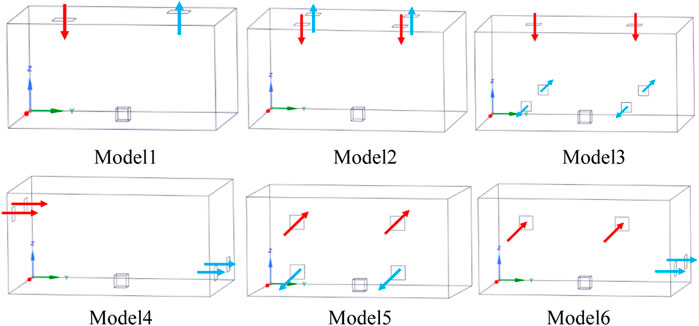
FIGURE 2. Optimal design of the vent.
In mesh division, the physical model is divided by an unstructured mesh of poly-hexcore. The leakage orifice adopts local mesh refinement and adds boundary layers to the wall to describe the gas flow in the leakage orifice and the boundary area for refinement.
In the Fluent solver setting, the flow of tritium gas in the air is multiple species transport, and it has complex flow types including jet and diffusion, setting the species transport model and the realizable k–ε turbulence model (Shih et al., 1995).
In the boundary condition setting, the tritium gas leakage outlet is defined as a mass flow inlet and establishes the relationship between mass flow rate, leakage outlet pressure, temperature, and the time by using the user-defined function (UDF) to compile interface codes, and the ventilation duct is defined as the velocity inlet. In the material setting (Huang, 2002), the mole mass of tritium is 6.034 kg kmol−1, and the diffusion coefficient in air is 7.41 × 10⁻⁶ m2 s−1. The wall material of the confined space is calcium-carbonate, and the storage wall material is steel. The semi-implicit method for pressure-linked equations is used to simulate the flow field.
The simulation results were compared with the experimental data of “Caisson” tritium release in JAERI to verify the reliability of the numerical simulation method for tritium leakage (Hayashi et al., 2000). The simulation conditions are the same as the “Caisson” tritium release experiment, and numerical simulation is carried out based on Fluent. Figure 3 shows the geometrical model of “Caisson,” selecting three monitoring points in “Caisson,” T1, T2, and T3, to monitor the variation of tritium concentration, as shown in Figure 4.
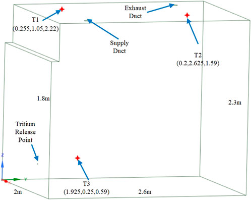
FIGURE 3. Geometrical model of Caisson.
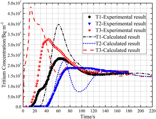
FIGURE 4. Tritium concentration comparison between experimental results and calculated results at monitoring points.
Figure 4 shows the tritium concentration comparison between calculated results and “Caisson” experimental results; the result shows that the tritium concentration at T3 nearest tritium release point increases rapidly in the tritium release initial stage and the tritium concentration at T2 farthest tritium release point increases gradually at 40 s. The time of tritium concentration increasing is different between calculated results and experimental results, and the main reason is that the time lag of tritium gas flowing into “Caisson” after release is not considered in simulation. The simulated tritium concentration is larger than that of the experimental, and the tritium concentration variation at monitoring points has obvious fluctuations. The tritium concentration at T2 decreases and increases in the range of 70–120 s before becoming stable, which may be caused by the weak airflow nearing the exhaust outlet. There are some errors in the calculated results that may be caused by less amount of tritium release. The tritium concentration tends to be stable in calculated and experimental results after 120 s of tritium release, and both tritium concentration stable values of calculated results and experimental results are 1.5 × 10⁷ Bq m−3. The calculated results are in good agreement with experimental results. The result shows that the model can be used to simulate tritium release behavior.
In order to accurately describe the transient behavior of tritium leakage, the tritium leakage process is simulated and gets the XZ plane tritium leakage velocity contour at y = 2.5 m when t = 1s, t = 3s, and t = 4.5 s, as shown in Figure 5.
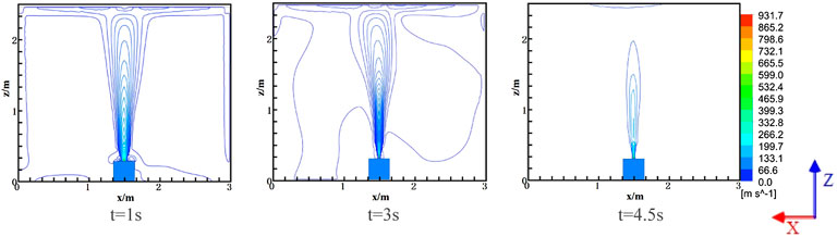
FIGURE 5. Velocity contour in the XZ plane at y = 2.5 m.
Figure 5 shows the tritium leakage velocity contour in the XZ plane at y = 2.5 m; it can be seen from the simulation results that the leakage rate of tritium gas is large, and the flow in space is jet flow in the early stage of tritium leakage in the high-pressure storage vessel. The jet flow of tritium gas is impeded by the closed space, as shown in Figure 5 t = 1 s. With the continuous leakage, the leakage velocity of tritium gas decreases, and the jet flow phenomenon weakens gradually, as shown in Figure 5 t = 4.5 s.
In order to analyze the effect of different ventilation scenes on the tritium gas migration after leakage, the simulation calculation is carried out in six ventilation scenes, with the ventilation flow rate remained at 1 m3·s-1, and the tritium gas flow velocity vectors at different time points in the plane with the exhaust vent in six scene spaces are obtained, as shown in Figure 6.
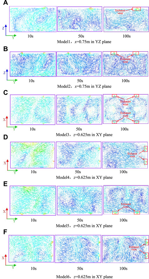
FIGURE 6. Tritium gas flow velocity vector, m·s−1.
Figure 6 shows the tritium gas flow velocity vector at different time points in the plane with an exhaust vent in six scene spaces. The part labels of Figures 6A–F expressed as the 216 location of exhaust vent plane in six scenes space. The figure shows that there are different sizes and quantities of vortexes in the velocity field of the plane where the exhaust vents of the six models are located. The vortexes in model 1 at 10 s are stronger and approximately symmetric distribution. With the continuous ventilation, the vortex gradually moves away from the vent and mainly distributes in the edge of the plane when the airflow in the space tends to be stable (t = 100 s), and the airflow of the exhaust vent mainly comes from the right bottom of the plane, as shown in Figure 6A. Model 2 increases the vent compared with model 1, which leads to a total different formation and distribution of vortex in the plane. There are fewer vortexes in the plane before the airflow in the space is stable, and more vortexes are formed in the plane after the airflow is stable. Moreover, the swirling flow in the plane can flow to the exhaust vent in different directions, as shown in Figure 6B. Model 3 increases two exhaust vents and changes the position of the exhaust vent compared with model 2. According to the figure, the gas flow rate is larger, and the vortex phenomenon is not obvious at 10 s. As the velocity of gas flow decreases in the space, the swirling flow of the velocity field intensifies gradually. The vortex distribution is complex at 100 s; however, the airflow of the exhaust vent only comes from the swirl near four corners, and the swirl in the middle area of the plane does not flow to the exhaust vent, as shown in Figure 6C. The flow velocity is large, and the vortex phenomenon is not obvious in the plane of model 4 before the airflow is stable, and the vortex is mainly distributed on the side away from the exhaust vent after the airflow is stable (t = 100 s). Most of the airflow in the plane flows to the vortex concentration area, and only a few flows to the exhaust vent, as shown in Figure 6D. The swirl intensity is weak in the exhaust vent plane of model 5. When t = 10 s, the airflow velocity is large, and the left airflow flows from left to right and the right airflow flows from right to left; the airflow gradually flows to the two exhaust vents as the airflow rate decreases, as shown in Figure 6E. The exhaust vent of model 6 is the same as model 4; the vortex is distributed at the bottom of the plane and approximately symmetric at 10 s, and the left swirling flow is clockwise, while the right swirling flow is counterclockwise. The number of swirling flows in model 6 is more than that in model 4, and the distribution is more complex. The swirling flow in the middle area flows to two exhaust vents, as shown in Figure 6F.
The setting of air inlet and exhaust outlet has a great influence on gas flow in the space. In order to analyze the influence of airflow in different ventilation scenes on tritium gas mixing behavior, simulation calculation is carried out on the scene after airflow is stable, obtaining the distribution of vortex core region in the space with a vortex strength of 1 s−1, as shown in Figure 7.
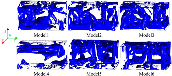
FIGURE 7. Vortex core region distribution.
Figure 7 shows the distribution of the vortex core region in the space with a vortex strength of 1 s−1 after the airflow is stable. The result shows that the vortex core region with a vortex strength of 1 s−1 is mainly distributed in the air inlet and a few are distributed in the exhaust vent of the six models. The vortex core region distribution in model 2, model 3, and model 6 is more complex, while the vortex core region distribution in model 4 is less complex. The vortex core region is mainly distributed on the left side of the space in model 1 and the vortex core region is mainly distributed in the lower part of the space in model 2 and model 3, while the vortex core region is mainly distributed in the upper part of the space in model 4, model 5, and model 6. The result shows that the setting of the air inlet has a great influence on the distribution of the vortex core region.
In order to analyze the tritium concentration distribution in the process of detritiation in the six ventilation scenes, the simulation calculation is carried out at 830 s after tritium leakage, obtaining the tritium concentration distribution in the space, as shown in Figure 8. In order to accurately analyze the variation of tritium concentration and quantitatively analyze the ventilation time required to decrease tritium concentration to the background level after a tritium leakage accident, two points P1 and P2 are selected in the space to monitor the variation of tritium concentration, as shown in Figure 9. The point P1 (1.5, 2.5, and 1.5) is above the storage vessel, and the point P2 is the point with high tritium concentration in six models, model 1-P2 (0.75, 3.25, and 1.5), model 2-P2 (0.75, 4.375, and 0.625), model 3-P2 (1.5, 2.5, and 2.2), model 4-P2 (2.25, 0.625, and 0.225), model 5-P2 (0.75, 1.875, and 0.625), and model 6-P2 (2.25, 4.375, and 0.625).
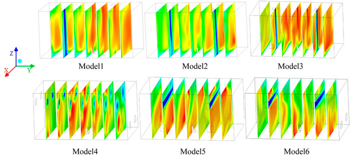
FIGURE 8. t = 830 s, tritium concentration distribution in the space, kg·m−3.
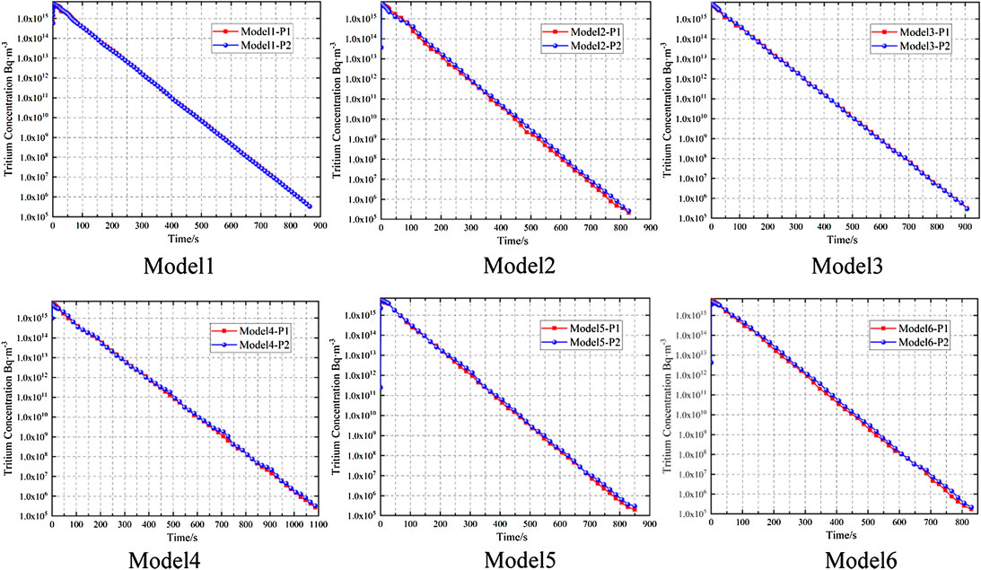
FIGURE 9. Variation of tritium concentration at monitoring points in the space.
Figure 8 shows the tritium concentration distribution of six ventilation scenes at 830 s. The result shows that the tritium concentration of model 1 is lower in the air inlet area and higher in the exhaust outlet area. According to the result of Figure 7 model 1, the tritium concentration in the swirl concentration distribution region is significantly lower than that in the weak swirl intensity region. Model 2 increases an air inlet and outlet compared with model 1 with the same air inlet and outlet area. Model 2 has a lower tritium concentration in the space except for a higher concentration on the right side of the exhaust vent. There is low tritium concentration in the concentration vortex core region and high tritium concentration in the weak intensity vortex core region, which indicates that the vortex can promote the mixture of air and tritium gas and effectively decrease the tritium concentration. The tritium gas in model 3 is mainly distributed in the central region of the space and is obviously higher than that in model 1 and model 2. Although the vortex core region distribution in model 3 is similar to model 2, the tritium concentration is lower in model 2 with a different exhaust vent setting. The result shows that the tritium concentration is affected not only by the vortex core region but also by the exhaust vent setting. The mass fraction of tritium is less than that of air, and it is distributed in the upper part of the space under the effect of full buoyancy. When the exhaust vent is set on the roof, the diluted tritium gas can be effectively discharged. When the exhaust vent is set at the lower part of the space, it can only decrease local tritium concentration and has a low tritium removal efficiency for the upper part of the space. The tritium concentration in the upper part region is obviously lower than that in the lower part region in model 4, which indicates that the tritium concentration dilutes faster in the upper part affected by swirling flow. According to the results of Figure 6D model 4, most of the airflow flows away from the exhaust vent, and only a few airflow flows to the exhaust vent, which leads to a high tritium concentration in an area far away from the exhaust vent and has a low tritium removal efficiency in model 4. There is a little difference in tritium concentration distribution in the space between model 5 and model 6. According to the results of Figure 6F model 6, the swirl distribution in the exhaust vent plane is more complex than that in model 5, which makes the tritium concentration decrease faster in model 6 and has higher tritium removal efficiency.
Figure 9 shows the variation of tritium concentration at monitoring points in the space. In order to analyze the tritium concentration variation clearly, the axis of ordinate is distributed logarithmically. The result shows that the tritium concentration at two monitoring points in six ventilation scene spaces has little difference and can be ignored. It needs to ventilate for about 860 s for the tritium concentration in the space to decrease to the background level (Cristescu et al., 2005) (3 × 10⁵ Bq m−3) in model 1, about 830 s in model 2, 910 s in model 3, 1100 s in model 4, 850 s in model 5, and 830 s in model 6. It can be seen that there is less ventilation time in the model with complex vortex core region distribution and more ventilation time in the model with weak intensity vortex core region distribution. When the vortex core region is distributed in the low part area and the exhaust vent is set in the low part of the space, it can only improve local tritium removal efficiency. When the vortex core region is distributed in the lower part area while the exhaust vent is set in the upper part of the space or the vortex core region is distributed in the upper part area with a lower part exhaust vent setting, it can improve overall tritium removal efficiency. The result shows that the tritium removal efficiency is not only affected by swirling flow but also by the exhaust vent position. In summary, model 2 and model 6 require less ventilation time after tritium leakage and has the highest tritium removal efficiency, which can be regarded as optimization emergency ventilation design methods under the tritium leakage accident conditions.
Aiming at the problem of tritium leakage accident of high-pressure storage vessel in the room, the study carries out the numerical simulation research of tritium high-pressure release behavior based on Fluent, using UDF to perform the coupling calculation of the AN-EOS tritium leakage model and Fluent, which describes the transient behavior of high-pressure tritium leakage. Then, the simulation calculation of tritium migration and mixing behavior in six ventilation scenes is carried out, and the effect of different ventilation scenes on tritium removal efficiency is analyzed in the study, which realizes the optimal design of emergency ventilation under the tritium leakage accident conditions. The result shows that the tritium gas forms a strong jet flow in the space when the high-pressure storage vessel causing tritium leakage in the room, and the closed space can impede the jet flow of tritium gas. In the tritium removal phase, different ventilation scenes lead to different swirl distributions in the space, and the complex distribution of the vortex core region can effectively promote the mixing behavior of tritium gas. Therefore, the tritium concentration decreases faster in the concentration vortex core region while slower in weak swirl intensity. When the distribution of the vortex core region is opposite to the position of the exhaust vent, the overall tritium removal efficiency in the space can be effectively improved and it can only improve local tritium removal efficiency, while the distribution of the vortex core region is the same with the position of the exhaust vent. Model 2 and model 6 ventilation scenes can form complex vortex core region distributions in the space, which leads to the least ventilation time of tritium concentration to recover to the environmental level and the highest overall tritium removal efficiency. They can be used as the optimal design of tritium leakage emergency ventilation in the room.
The original contributions presented in the study are included in the article/Supplementary Material; further inquiries can be directed to the corresponding author.
CL: writing—original draft. XC: conceptualization and methodology. MX: formal analysis and investigation. YH: validation. PX: writing—review and editing. SL: resources.
The authors declare that the research was conducted in the absence of any commercial or financial relationships that could be construed as a potential conflict of interest.
All claims expressed in this article are solely those of the authors and do not necessarily represent those of their affiliated organizations, or those of the publisher, the editors, and the reviewers. Any product that may be evaluated in this article, or claim that may be made by its manufacturer, is not guaranteed or endorsed by the publisher.
Arjmandi, H., Amini, R., Kashfi, M., Abikenari, M. A., and Davani, A. (2022). Minimizing the COVID-19 Spread in Hospitals through Optimization of Ventilation Systems. Phys. Fluids 34 (3), 037103. doi:10.1063/5.0081291
Carlson, R. V., Damiano, F. A., and Binning, K. E. (1985). Operation of the Room Air Tritium Removal System at the Tritium Systems Test Assembly. Fusion Technol. 8, 2190–2195. doi:10.13182/fst85-a24607
Cristescu, I.-R., Travis, J., Iwai, Y., Kobayashi, K., and Murdoch, D. (2005). Simulation of Tritium Spreading in Controlled Areas after a Tritium Release. Fusion Sci. Technol. 48 (1), 464–467. doi:10.13182/fst05-a966
Hayashi, T., Kobayashi, K., Iwai, Y., Yamada, M., Suzuki, T., O'hira, S., et al. (2000). Tritium Behavior in the Caisson, a Simulated Fusion Reactor Room. Fusion Eng. Des. 51-52, 543–548. doi:10.1016/s0920-3796(00)00214-3
Hayashi, T., Kobayashi, K., Iwai, Y., Yamanishi, T., Nishi, M., Okuno, K., et al. (1998). Tritium Behavior Intentionally Released in the Radiological Controlled Room under the US-Japan Collaboration at TSTA/LANL. Fusion Technol. 34, 521–525. doi:10.13182/fst98-a11963665
Iwai, Y., Hayashi, T., Kobayashi, K., and Nishi, M. (2001). Simulation Study of Intentional Tritium Release Experiments in the Caisson Assembly for Tritium Safety at the TPL/JAERI. Fusion Eng. Des. 54, 523–535. doi:10.1016/s0920-3796(00)00581-0
Johnston, I. A. (2005). The Noble-Abel Equation of State: Thermodynamic Derivations for Ballistics Modelling[R]. Melbourne, Australia: Defence Science and Technology Organisation Edinburgh (Australia) Weapons Systems Div.
Kobayashi, K., Hayashi, T., Iwai, Y., Yamanishi, T., Willms, R. S., and Carlson, R. V. (2008). Tritium Behavior Intentionally Released in the Room. Fusion Sci. Technol. 54 (1), 311–314. doi:10.13182/fst08-a1820
Li, W., Kou, H., Zeng, X., Cui, Y., Chen, H., and Wang, F. (2020). Numerical Simulations on the Leakage and Diffusion of Tritium. Fusion Eng. Des. 159, 111749. doi:10.1016/j.fusengdes.2020.111749
Li, X., Bi, J., and Christopher, D. M. (2013). Thermodynamic Models of Leaks from High-Pressure Hydrogen Storage Systems[J]. J. Tsinghua Univ. Sci. Technol. 53 (4), 503–508. doi:10.16511/j.cnki.qhdxxb.2013.04.027
Liu, G., Fu, W., and Song, J. (2017). Study on Relation of Tritium Concentration and Ventilation under Leakage Accident of Glove Box in TES of TBM[J]. Nucl. Electron. Detect. Technol. 37 (2), 211–215.
Liu, G. (2017). Simulation Study of Accidental Tritium Release on Tritium Extraction System of TBM[D]. Hengyang: University of South China.
Mei, Feng, Wei, Yingjing, Li, Dehong, Wang, Yong, Zhang, Qingli, Wang, Mingliang, et al. (2020). Establishment of Tritium Activity Concentration Standard Device. J. Radiat. Prot. 40, 271–277.
Munakata, K., Wajima, T., Hara, K., Wada, K., Takeishi, T., Shinozaki, Y., et al. (2010). Tritium Release Experiments with CATS and Numerical Simulation. Fusion Eng. Des. 85, 1250–1254. doi:10.1016/j.fusengdes.2010.03.011
Shih, T. H., Liou, W. W., and Shabbir, A. (1995). A New K-ϵ Eddy Viscosity Model for High Reynolds Number Turbulent Flows[J]. Comput. fluids 24 (3), 227–238.
Wei, S. (2021). Study on Inner Fuel Cycle and Tritium Transport Simulation for CFETR Tritium Plant[D]. Switzerland: Hefei: University of Science and Technology of China.
Keywords: tritium leakage, emergency treatment, optimal ventilation, nuclear reactor, tritium removal efficiency
Citation: Li C, Cai X, Xiao M, Huo Y, Xu P and Li S (2022) Analysis on Emergency Treatment Effect of Tritium Leakage Accident in the Nuclear Reactor Under Different Ventilation Conditions. Front. Energy Res. 10:963990. doi: 10.3389/fenrg.2022.963990
Received: 08 June 2022; Accepted: 10 June 2022;
Published: 15 July 2022.
Edited by:
Shichang Liu, North China Electric Power University, ChinaReviewed by:
Wenxi Tian, Xi’an Jiaotong University, ChinaCopyright © 2022 Li, Cai, Xiao, Huo, Xu and Li. This is an open-access article distributed under the terms of the Creative Commons Attribution License (CC BY). The use, distribution or reproduction in other forums is permitted, provided the original author(s) and the copyright owner(s) are credited and that the original publication in this journal is cited, in accordance with accepted academic practice. No use, distribution or reproduction is permitted which does not comply with these terms.
*Correspondence: Xingfu Cai, MTc3OTE0Nzc3NDBAc2luYS5jbg==
Disclaimer: All claims expressed in this article are solely those of the authors and do not necessarily represent those of their affiliated organizations, or those of the publisher, the editors and the reviewers. Any product that may be evaluated in this article or claim that may be made by its manufacturer is not guaranteed or endorsed by the publisher.
Research integrity at Frontiers
Learn more about the work of our research integrity team to safeguard the quality of each article we publish.