 Omar E. M. Youssef
 Mohamed G. Hussien
 Abd El-Wahab Hassan2,3
- 1Electrical Engineering Department, Faculty of Engineering at Shoubra, Benha University, Cairo, Egypt
- 2Department of Electrical Power and Machines Engineering, Higher Institute of Engineering (HIE), El-Shorouk Academy, El-Shorouk City, Egypt
- 3Department of Electrical Power and Machines Engineering, Faculty of Engineering, Tanta University, Tanta, Egypt
A field-orientation scheme is a typical control technique of induction motors to obtain sophisticated performance. The stator field-oriented control is less sensitive to parameter variations than the rotor field-oriented control. In addition, the estimation of the stator flux is more accurate than that of the rotor flux. Therefore, the stator flux system is considered a good choice for variable speed drives. However, the traditional configuration of the system includes four PI controllers which need effort in tuning. In this article, simple calculations are proposed such that the configuration and performance of the stator field-oriented control systems are improved by including only two PI controllers. In addition, with the aid of the machine phase axes, a simple procedure for the speed estimation target is suggested to effectively estimate the rotor speed of the machine with a direct estimation without any need for a PI controller or additional observers in the speed observer procedure. The obtained results confirm the effectiveness of the proposed control scheme.
Introduction
A field-oriented control (FOC) is a common control technique used in induction motor drives. Using this technique, a high performance is obtained due to the torque, and the flux is controlled independently, similar to a separately excited DC motor. There are direct FOC (DFOC) and indirect FOC (IFOC). In DFOC, the calculation of the field vector is based on motor terminal variables, and in IFOC, there are estimations that include the slip frequency of the motor. Initially, the control schemes were established on rotor FOC (RFOC). However, calculations in rotor field orientation depend on rotor resistance and on inductances, which are varied by temperature and magnetic saturation, respectively. An alternative technique to RFOC is the direct stator FOC (DSFOC) because the estimation of stator quantities is more accurate than the estimation of rotor quantities. Also, the accuracy of estimation of the stator flux depends only on the stator resistance, and it is not affected by the inductances of the motor. However, the effect of variation of the stator resistance on the accuracy of estimation at low frequencies is considerable. Also, using a pure integrator in the estimation of the stator flux builds up a dc offset at low frequencies. In addition, there is a dynamic-coupling effect between the motor speed and the stator flux. Several solutions are proposed for these problems. Solutions to the problem of variation of the stator resistance are such as in Nagataki et al. (2020) and Bai-shan and Wen-qi, (2010), solutions to the problem of pure integrators are such as in Liu et al. (2007), Zhang and Dai, (2010), Man and Chen, (2011), and Luo et al. (2020), combined solutions to both problems are such as in Mitronikas et al. (2001), Mitronikas and Safacas, (2004), Lee et al. (2014), and Mei and Feng, (2014), and solutions to the problem of coupling effects between the motor speed and the stator flux are such as in Liu et al. (2007) and Amiri and Khaburi, (2012).
In the classical DSFOC scheme, there are four PI controllers, namely, a torque controller, a flux controller, and two current controllers, and tuning of these controllers represents a burden on the design of the control system. Because of the nonlinear nature of induction motor parameters, there are many attempts to replace the linear (PI) controllers with nonlinear controllers such as in Salvatore et al. (2007), Zhang et al. (2010), and Nguyen et al. (2020). However, all these control schemes suffer from the difficulty of design and the burden of calculations.
In this article, a simplified structure of sensorless DSFOC is proposed. In the proposed scheme, the torque and flux controllers of the classical DSFOC are replaced with simple calculations, and an improved procedure implemented by the author in the previous work (Hussien, 2020) for speed estimation is combined with the control system without any need for a PI controller in the sensorless speed methodology. Using these calculations leads to simplifying the design of the control scheme and obtaining a fast response to sudden changes. In addition, the transient current is limited to an allowable overload value of the variable-frequency drive, and the speed deviation is taken equal to a specified value. The proposed control scheme is validated by the results.
Traditional direct stator FOC system
The basic configuration of the DSFOC system is described in Figure 1. In this configuration, the stator voltages and the stator currents are used to estimate the stator flux vector. Then, the stator currents in the stator-flux frame, iqs(λ) and ids(λ), are estimated, where the subscript (λ) indicates the stator-flux frame. The differences between these currents and the corresponding reference stator currents, iqs(λ)-ref and ids(λ)-ref, are the inputs of two PI (current) controllers to produce the reference stator voltages, uqs(λ)-ref and uds(λ)-ref, which are used to determine the switching states of the PWM converter. To produce the reference stator currents, the differences between the reference speed (ωm-ref) and the motor speed (ωm) are the input of a PI (torque) controller, and the difference between the reference stator flux (λs-ref) and the motor flux (λs) is the input of a PI (flux) controller.
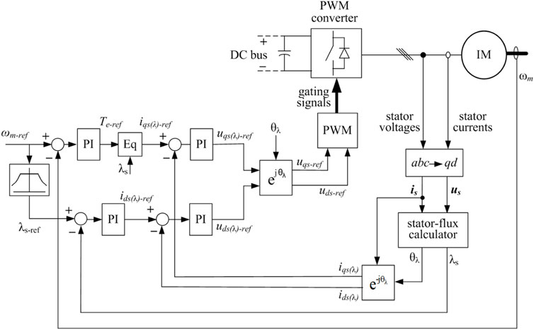
FIGURE 1. Typical DSFOC system.
The stator flux vector in the stationary reference frame is estimated as follows:
where λqs and λds are q-axis and d-axis components of the stator flux linkage in the stationary reference frame, respectively, uqs and uds are the stator-voltage components, iqs and ids are the stator-current components, θλ is the angle of the stator flux linkage, and Rs is the stator resistance.
Proposed direct stator FOC system
In the proposed control system, the reference currents iqs(λ)-ref and ids(λ)-ref are estimated by simple calculations without dependence on PI controllers, dissimilar to a typical DSFOC system. The configuration of the proposed system is shown in Figure 2. The calculations of the reference currents are as follows:
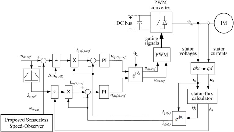
FIGURE 2. Proposed DSFOC system.
Calculation of the reference D-axis current (ids(λ)-ref)
In the stator-flux frame, the relationship between the stator flux (λs) and the stator current ids(λ) is expressed as follows (Krause et al., 2002):
where Ls is the stator self-inductance and Lm is the magnetizing inductance.
The stator flux λs can be controlled by the current component ids(λ). The task is to find an appropriate relationship of the reference current ids(λ)-ref instead of dependence on the PI controller. An appropriate expression, proposed by this work, is obtained by assuming that λs is directly proportional to ids(λ). Thus, the reference current ids(λ)-ref can be taken as
where ids(λ)-AOL is the allowable overload value of ids(λ) and the value of λs is estimated using Eq. 3.
Calculation of the reference Q-axis current (iqs(λ)-ref)
In this work, instead of tracking the reference motor speed (ωm−ref), an allowable deviation from this speed (Δωm-AD) is tracked. The current iqs(λ)-ref is estimated as follows:
The motor torque (Te) can be given by (Krause et al., 2002)
where P is the number of pole pairs.
At a certain value of the stator flux (λs),
where the torque Te can be given by
where TL, Bm, ωm, and J are the load torque, friction coefficient, motor speed, and inertia, respectively.
Thus,
Thus, the change of speed (Δωm) can be controlled by the current component iqs(λ). By assuming that Δωm is directly proportional to iqs(λ), an appropriate expression of iqs(λ)-ref is obtained, without dependence on the PI controller, as follows:
where Δωm-AD is an allowable deviation of the motor speed from the reference speed and iqs(λ)-AOL is the allowable overload value of iqs(λ).
Current limits
There is an allowable overload current (is-AOL) of the variable-frequency drive. This value can be 150% for 1 min. To limit the stator current to this value, the values of ids(λ)-AOL and iqs(λ)-AOL are estimated as follows:
The priority is given to the reference current ids(λ)-ref over the current iqs(λ)-ref because the establishment of the flux leads to maximum torque per ampere during the dynamic performance, thus minimizing the current iqs(λ).
Proposed speed-estimation procedure for the sensorless direct stator FOC system
It is mainly obvious from the presented algorithm of DSFOC for the adopted IM that its procedure is fully dependent on the knowledge of the speed signal required for the field-oriented scheme.
Due to the issues associated with the need for a mechanical speed sensor such as the maintenance problems and the high cost required and other issues of reliability, it is important to assure the implementation of the proposed DSFOC system with a more sufficient sensorless speed observer (Kumar and Goyal, 2018; Sun et al., 2021; Kumar et al., 2022). Hence, to attain this target, a high-performance sensorless speed-estimation procedure is handled in this article with the aid of the suggested senseless algorithm implemented by the author in the previous work (Hussien, 2020). The suggested sensorless scheme is considered with the aid of the machine phase axes with a simplified algorithm without any need for any extra observation methodologies or PI controllers in the process of the speed observer.
After observing the IM’s flux angle of the stator side, θλ, using Eq. 4, the corresponding angular speed of the reference frame,
The quantities ‘X’ and ‘Y’ represent the flux-angle’s, θλ, triangular components.
Based on the proposed DSFOC procedure, the slip angular slip-speed, ωsl, is realized as
where
Here, the symbols Lr and Rr represent the rotor self-inductance and resistance, respectively.
Aided with Eqs. 15, 16, the associated estimation of the mechanical rotor speed is obtained as
Results and discussion
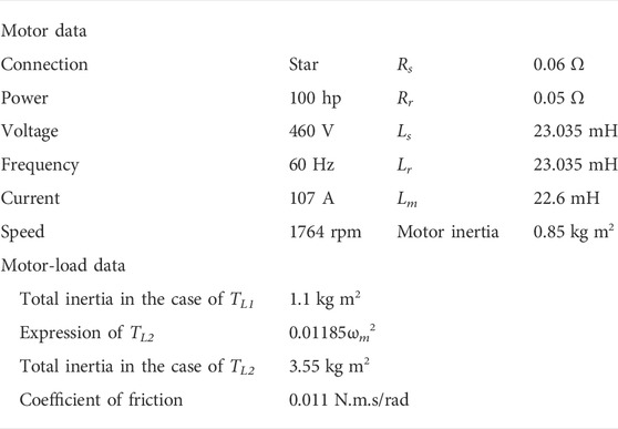
The simulation results are obtained by MATLAB/SIMULINK (The MathWorks, 2022). Two different load types are used in the simulation: the load TL1 has a constant torque, and the load TL2 is a centrifugal load with a torque proportional to the square of the motor speed and has a rated torque at the rated speed of the motor. The allowable overload current (is-AOL) is taken equal to 1.5 pu, and the allowable deviation of the motor speed (Δωm-AD) is taken equal to 2 rpm. The data of the system are listed as shown.
The results with TL1 equal to 1.0 pu and stepped changes of the reference speed are shown in Figure 3. Figure 3A shows that the reference speed is tracked, and the deviation of speed is about 2 rpm with a good tracking between the estimated speed response and its corresponding actual level. Figure 3B shows that the stator current is limited during the transient periods to about 1.5 pu. Also, Figure 3C shows that the electromagnetic torque is limited during the transient periods to about 1.5 pu and −1.5 pu, corresponding to acceleration and deceleration, respectively. A similar performance in the case of the load TL2 is shown in Figure 4.
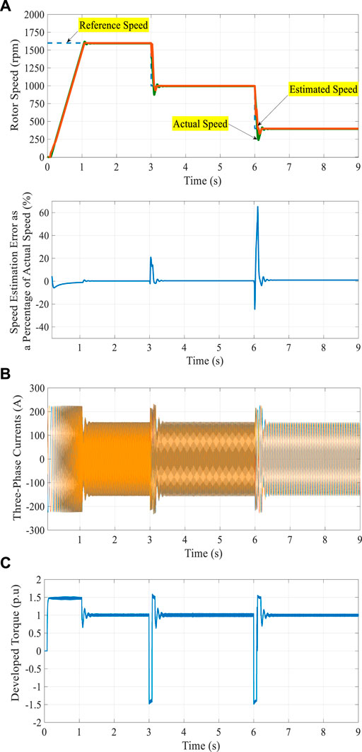
FIGURE 3. Results of the proposed control system with TL1 equal to 1.0 pu and stepped changes of the reference speed.
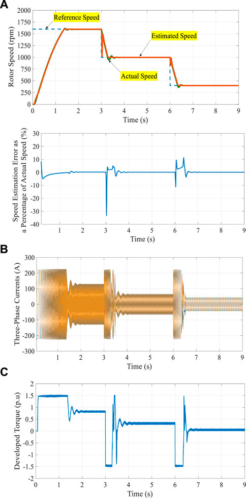
FIGURE 4. Results of the proposed control system with TL2 and stepped changes of the reference speed.
The results with TL1 equal to 1.0 pu and ramped changes of the reference speed are shown in Figure 5 including the operation under the low-speed region. As shown in Figure 5A, the speed is changed from 1,600 rpm (high-speed region) to 500 rpm and then followed by a ramp change from 500 rpm to 100 rpm (low-speed region). The reference speed is tracked, and the validity of the suggested speed estimation methodology is confirmed as shown in Figure 5A. The corresponding current and torque are shown Figures 5B,C,respectively.
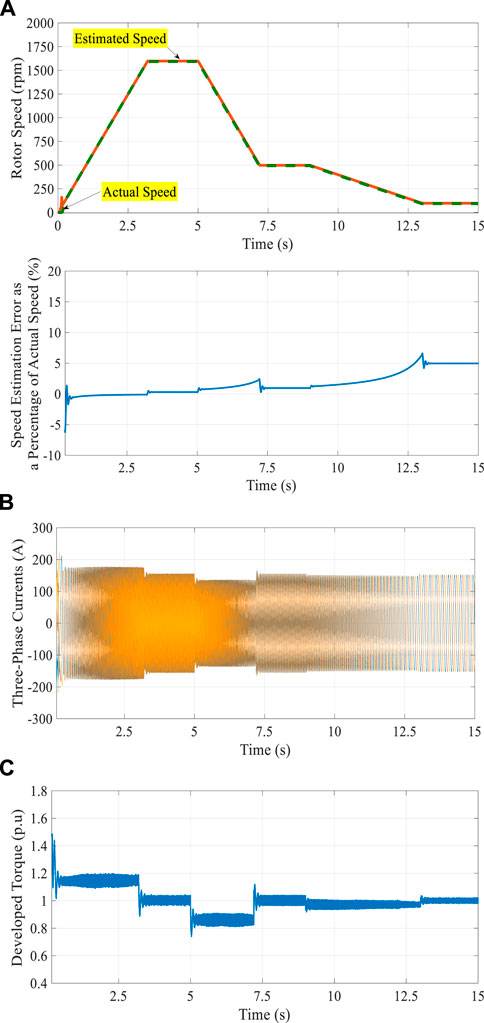
FIGURE 5. Results of the proposed control system with TL1 equal to 1.0 pu and ramped changes of the reference speed.
During the dynamic performance, the values of current and torque are far from the maximum limit (1.5 pu) because of the small difference between the reference speed and the motor speed. Figure 6 shows the results with the stepped change of TL1, after approaching the steady state, from 1.0 pu to 0.5 pu at a time equal to 3.0 s. The results show no disturbance in the motor speed, and a fine speed control is achieved with a close correlation between the estimated rotor-speed response and its corresponding actual level. This confirms the observability and controllability of the speed-estimation procedure for the adopted simplified DSFOC system of IM drives.
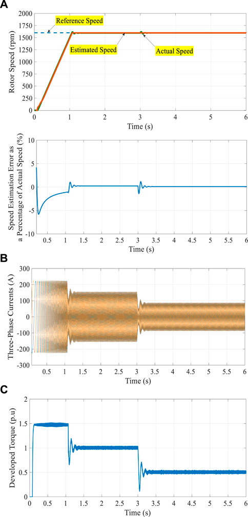
FIGURE 6. Results of the proposed control system with TL1 are stepped changed from 1.0 pu to 0.5 pu at a time equal to 3.0 s.
Conclusion
Using the direct stator flux-oriented control (DSFOC) in variable speed drives is motivated by the accuracy of the estimation of the stator flux and little dependence on the machine parameters. The conventional configuration of the DSFOC control scheme has four PI controllers: a torque controller, a flux controller, and two current controllers. Tuning all these controllers is not a simple task during the design of the control system. This article has suggested the replacement of two PI controllers by simple calculations, such that the final configuration of the system includes two PI (current) controllers. By these calculations, the transient current is limited to an allowable overload value of the variable-frequency drive. Also, a specified allowable deviation value of the motor speed from the reference speed is used in the proposed calculations for all speeds. In addition, a simple topology to efficiently predict the mechanical speed of IM has been handled and investigated for a sensorless drive system based on the DSFOC algorithm. The results of the proposed control system show excellent speed control and dynamic performance including the operation under the low-speed region. Moreover, the speed observer simply has not required any extra observers or controllers in the estimation procedure which has assured the cost-effective properties of the presented drive system.
Data availability statement
The original contributions presented in the study are included in the article/Supplementary Material; further inquiries can be directed to the corresponding author.
Author contributions
All authors listed have made a substantial, direct, and intellectual contribution to the work and approved it for publication.
Conflict of interest
The authors declare that the research was conducted in the absence of any commercial or financial relationships that could be construed as a potential conflict of interest.
Publisher’s note
All claims expressed in this article are solely those of the authors and do not necessarily represent those of their affiliated organizations, or those of the publisher, the editors, and the reviewers. Any product that may be evaluated in this article, or claim that may be made by its manufacturer, is not guaranteed or endorsed by the publisher.
References
Amiri, S., and Khaburi, D. A. (2012). “Decoupled stator flux oriented control for induction motor fed by indirect matrix converter,” in 2012 3rd power electronics and drive systems Technology (Tehran, Iran: PEDSTC), 199–205.
Bai-shan, M., and Wen-qi, H. (2010). “Stator resistance compensation based on fuzzy logic control in SFOC system,” in Proc. International Conference on Intelligent System Design and Engineering Application, Changsha, China, 408–411.
Hussien, M. G. (2020). A new robust sensorless vector-control strategy for wound-rotor induction motors. Aust. J. Electr. Electron. Eng. 17, 132–137. doi:10.1080/1448837x.2020.1800191
Krause, P. C., Wasynczuk, O., and Sudhoff, S. D. (2002). Analysis of electric machinery and drive systems. Second Edition. BookIEEE Press.
Kumar, B., and Goyal, T. (2018). “Investigations on flux estimation methods for stator current based MRAS speed estimator for induction motor drive,” in Proc. 2018 IEEMA Engineer Infinite Conference (eTechNxT).
Kumar, M., Kumar, B., and Rani, A. (2022). A novel loss model control-based efficiency enhancement scheme for IFOC induction motor drive. Arab. J. Sci. Eng. doi:10.1007/s13369-022-06706-8
Lee, S., Park, G., and Jung, M. (2014). “Sensorless stator flux oriented control of induction motors using PLPF with flux error compensator,” in Proc. IEEE Vehicle Power and Propulsion Conference (VPPC).
Liu, G., Lu, J., and Zhang, H. (2007). “A stator flux-oriented decoupling control scheme for induction motor,” in Proc. IEEE International Conference on Control and Automation (Guangzhou, CHINA.
Luo, Y.-C., Chen, B.-W., Pu, W.-C., and Pai, N.-S. (2020). Speed estimation direct stator field-orientation-controlled induction motor drive using adaptive flux estimator. Sensors Mater. 32 (1), 239–252. doi:10.18494/sam.2020.2574
Man, Y., and Chen, X. (2011). “The space vector control for induction motors based on stator flux orientation,” in Proc. 6th IEEE Conference on Industrial Electronics and Applications, 1265
Mei, B., and Feng, J. (2014). “Study on stator flux oriented sensorless induction motor control system,” in Proc. 17th International Conference on Electrical Machines and Systems (Hangzhou, China: ICEMS), 758–762.
Mitronikas, E. D., and Safacas, A. N. (2004). “A hybrid sensorless stator-flux oriented control method for induction motor drives,” in Proc. 35th Annual IEEE Power Electronics Specialists Conference (Germany: Aacken).
Mitronikas, E. D., Safacas, A. N., and Tatakis, E. C. (2001). A new stator resistance tuning method for stator-flux-oriented vector-controlled induction motor drive. IEEE Trans. Ind. Electron. 48 (6), 1148–1157. doi:10.1109/41.969393
Nagataki, M., Kondo, K., Yamazaki, O., Yuki, K., and Nakazawa, Y. (2020). “Auto tuning method to identify motor stator and rotor parameter in field-orientation-controlled induction motor,” in Proc. IEEE Energy Conversion Congress and Exposition (ECCE) (Detroit, USA, 5805–5812.
Nguyen, V.-Q., Tran, Q.-T., and Duong, H.-N. (2020). Stator-flux-oriented control for three-phase induction motors using sliding mode control. J. Electr. Syst. 16 (2), 171─184.
Salvatore, N., Cascella, G. L., Stasi, S., and Cascella, D. (2007). “Stator flux oriented sliding mode control of sensorless induction motor drives by Kalman filter,” in Proc. The 33rd Annual Conference of the IEEE Industrial Electronics Society (IECON) Taipei, Taiwan, 956–961.
Sun, X., Li, T., Zhu, Z., Lei, G., Guo, Y., and Zhu, J. (2021). Speed sensorless model predictive current control based on finite position set for PMSHM drives. IEEE Trans. Transp. Electrific. 7 (4), 2743–2752. doi:10.1109/tte.2021.3081436
The MathWorks (2022). MATLAB for artificial intelligence. Available at: http://www.mathworks.com/.
Zhang, H., and Dai, X. (2010). “Stator flux oriented control with improved integrator for speed-sensorless induction motor drives, ” in Proc. International Conference on E-Product E-Service and E-Entertainment
Zhang, Y., Zhu, J., Xu, W., Hu, J., Dorrell, D. G., and Zhao, Z. (2010). “Speed sensorless stator flux oriented control of three-level inverter-fed Induction motor drive based on fuzzy logic and sliding mode control,” in Proc. IECON 2010 - 36th Annual Conference on IEEE Industrial Electronics Society, 2932─2937.
Keywords: induction motor, starting current, starting torque, variable-frequency drive, sensorless DSFOC system
Citation: Youssef OEM, Hussien MG and Hassan AE-W (2022) A new simplified sensorless direct stator field-oriented control of induction motor drives. Front. Energy Res. 10:961529. doi: 10.3389/fenrg.2022.961529
Received: 06 June 2022; Accepted: 01 September 2022;
Published: 26 September 2022.
Edited by:
Enhua Wang, Beijing Institute of Technology, ChinaReviewed by:
Xiaodong Sun, Jiangsu University, ChinaBhavnesh Kumar, Netaji Subhas University of Technology, India
Copyright © 2022 Youssef, Hussien and Hassan. This is an open-access article distributed under the terms of the Creative Commons Attribution License (CC BY). The use, distribution or reproduction in other forums is permitted, provided the original author(s) and the copyright owner(s) are credited and that the original publication in this journal is cited, in accordance with accepted academic practice. No use, distribution or reproduction is permitted which does not comply with these terms.
*Correspondence: Mohamed G. Hussien, bW9oYW1lZC5odXNzaWVuM0BmLWVuZy50YW50YS5lZHUuZWc=