 Pai Wang
 Minxia Li
95% of researchers rate our articles as excellent or good
Learn more about the work of our research integrity team to safeguard the quality of each article we publish.
Find out more
ORIGINAL RESEARCH article
Front. Energy Res. , 08 July 2022
Sec. Process and Energy Systems Engineering
Volume 10 - 2022 | https://doi.org/10.3389/fenrg.2022.956807
This article is part of the Research Topic CO2-Based Energy Systems for Cooling, Heating, and Power View all 7 articles
CO2 household air-conditioners are difficult to popularize due to their low efficiency. The use of the expander can reduce the throttling loss and increase the cooling capacity of the CO2 system. In this paper, a fully enclosed double-cylinder rotor expander is designed. The structure and working progress are introduced. The factors affecting the efficiency of the expander are theoretically analyzed. The results show that the design of high back pressure can greatly improve the efficiency. Moreover, the relative cylinder height of the first cylinder should be between 0.2 and 0.3, while the relative cylinder height of the second cylinder should be between 0.4 and 0.6. The relative eccentricity should be around 0.1. The expander is very suitable for the condition of high outlet temperature of the gas cooler. There is a peak mass flow rate when the efficiency of the expander is maximum. This paper provides theoretical support for the design and manufacture of expander.
Artificial refrigerants containing chlorofluorocarbons (CFCs) and hydrochlorofluorocarbons (HFCs) have a severe impact on the ozone layer (Qin et al., 2022). In terms of working substance, with the implementation of the Kigali amendment to the Montreal Protocol, the applications of traditional refrigerant (e.g., HFC with high GWP) are restricted (Abas et al., 2018; Heredia-Aricapa et al., 2020; Luo et al., 2022). Refrigerant replacement is an important part of environmental protection. Among the commonly used natural working fluids, CO2 is the most competitive with the characteristic of environmental friendliness, better heat transfer performance and fluidity, and so on (Cui et al., 2021). The application of CO2 as a natural refrigerant in heating, refrigeration, and air-conditioning systems has become a significant development trend (Wang et al., 2021).
However, the throttling loss of CO2 is large, and the COP of CO2 system is relatively low. Especially for household air-conditioners, CO2 systems are not competitive compared to traditional refrigerants.Lorentzen (1994) put forward the theory of introducing expander into refrigeration cycle for the first time, and believed that when the throttle valve is replaced by the expander, the efficiency of the system will be improved. Wei (2002) demonstrated the superiority of CO2 rotary expander through theoretical design and experimental verification of actual prototype, the results showed that the rotary expander is stable but the efficiency is low.Zhang et al. (2007) designed a double acting free piston expander, in which a slider-based inlet/outlet control scheme was used to realize a full expansion process for the expander. The isentropic efficiency of 62% was obtained from the p–V diagram analysis. Jiang et al. (2013) designed and produced a new two-rolling piston expander. The rotating speed of the expander ranged from 850 to 1,000 rpm, and its efficiency ranged from 28% to 33%. Hu et al. (2015) improved the two-rolling piston expander to increase its efficiency. The experimental results showed that the revised expander had a much higher efficiency compared to the primary one, reaching a maximum of 77% at the revolution speed of 867 rpm, and a maximum recovered expansion work of 242 W at the revolution speed of 770 rpm. Guan et al.(Haiqing et al., 2006) developed a swing piston expander prototype for replacing the throttling valve based on the thermodynamic analysis of the operating conditions of a CO2 transcritical cycle. The isentropic efficiency of the prototype could be more than 28% when running steadily and up to a maximum of about 44%.Ferrara et al. (2016) experimentally analyzed a reciprocating expander developed from a hydraulic motor. The isentropic efficiency would be around 40%.Yang et al. (2009) experimentally investigated the internal working process especially the internal leakage of a rotary vane expander prototype. Results showed that the volumetric efficiency increased from 17% to 30% and the isentropic efficiency from 9% to 23% at the speed of 800 rpm.Li (2019); Li et al. (2022) found that the external leakage of the suction stage of the expander was proposed as the main part of the leakage loss which accounts for 78.4% of the total leakage loss, far exceeding the sum of losses in other phases and other leakage.
Previously research mostly focused on large-capacity expanders. There is a lack of research on CO2 rotor expanders with small capacity for household air-conditioners. At the same time, the efficiency of the existing expanders is generally low. The leakage loss is the major problem affecting the efficiency of the rotor expander. In order to match the capacity of the household air-conditioner and improve the efficiency of the expander, a small fully enclosed double-cylinder CO2 rotor expander is designed in this paper. Theoretical analysis is carried out to study the factors affecting the efficiency of the small fully enclosed expander. This paper provides providing theoretical guidance for the design and manufacture of expanders for household air-conditioners.
Aiming to match the capacity of household air-conditioners, the rated capacity of the small fully enclosed double-cylinder CO2 rotor expander is 0.818 cm3 and the rated expansion ratio is 2.5. The small fully enclosed double-cylinder CO2 rotor expander consists of two sets of cylinders and rotors. Its structure is shown in Figure 1. The suction progress is controlled by the first cylinder which is always connected to the intake pipe. And the second cylinder is always connected to the exhaust pipe. The intermediate partition is used to reduce the heat transfer loss of the first and second cylinders. As the rotor rotates, the first rotor, the second rotor and the slide plate form a closed expansion space between the two cylinders. There is a definite angle between the sliding plates of the first and second cylinders to prevent the rotor from stopping due to force balance. The exhaust port of the first cylinder and the intake port of the second cylinder are connected through a connecting hole. Thus double-cylinder CO2 rotor expander does not require separate intake control. The CO2 working fluid is always flowing. Therefore, there is no cam valve stem opening and closing during the intake control process. The pressure pulsation of the system is reduced and the noise caused by the friction between the cam and the valve stem is eliminated. Meantime, in order to reduce the external leakage of the expander, double-cylinder CO2 rotor expander is designed as a fully enclosed type. The back pressure of the expander is high by introducing the high-pressure working fluid in the compressor into the expander.

FIGURE 1. Structure diagram of the small fully enclosed double-cylinder CO2 rotor expander.
Taking the first cylinder as the reference object, the working process of the double-cylinder rotor expander is as follows:
1) Suction process.
The suction process is shown in Figure 2. When the roller of the first cylinder moves to the rear edge of the inlet of the first cylinder, as shown in Figure 2A and Figure 2D, the suction process begins. The closed space formed by the right side of the slide plate in the first cylinder, the outer surface of the roller in the first cylinder and the inner wall of the cylinder is the suction chamber. At this time, the space formed by the left side of the slide plate in the first cylinder, the outer surface of the roller in the first cylinder and the inner wall of the first cylinder is in communication with the second cylinder. When the roller of the first cylinder moves to the rear edge of the outlet of the first cylinder, as shown in Figure 2B and Figure 2D, the right side of the sliding plate in the first cylinder continues to carry out the suction process. At this time, the working fluid is about to enter the second cylinder through the outlet of the first cylinder, and the second cylinder is about to start suction. When the roller of the first cylinder passes through the front edge of inlet in the first cylinder again, a new cycle starts, as shown in Figure 2C and Figure 2F.
2) Expansion process.
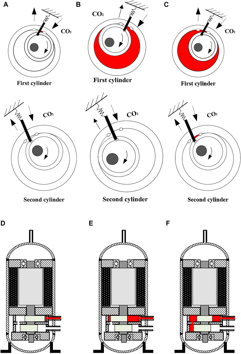
FIGURE 2. Suction progress. (A) Prepare for suction progress. (B) Suction progress. (C) End of suction progress. (D) Prepare for suction progress. (E) Suction progress. (F) End of suction progress.
The expansion process is shown in Figure 3. When the roller of the first cylinder moves to the front edge of the outlet of the first cylinder, the left side of the sliding plate in the first cylinder, the outer surface of the roller in the first cylinder and the inner wall of the cylinder form an enclosed space. At this time, the suction process has just been completed. As the roller continues to move, an expansion process occurs in this enclosed space until the roller of the second cylinder moves to the front edge of the outlet of the second cylinder.
3) Exhaust process.
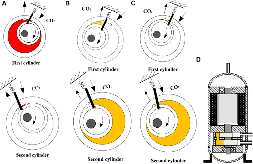
FIGURE 3. Expansion process. (A) Prepare for expamsion progress. (B) Expansion progress. (C) End of expansion progress. (D) Expansion progress.
The exhaust process is shown in Figure 4.When the roller of the second cylinder moves to the front edge of the outlet in the second cylinder, the cavity formed by the left side of the slide plate in the first cylinder, the outer surface of the roller in the first cylinder and the inner wall of the cylinder has just completed the expansion process. The exhaust process is about to start.
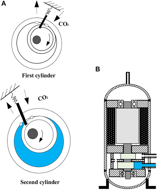
FIGURE 4. Exhaust process. (A) Exhaust process. (B) Exhaust process.
The irreversible loss of the expander is mainly friction loss and leakage loss. Force analysis of the sliding plate and the roller should be carried out first.
Force analysis diagram is shown in Figure 5.
1) The elastic force Fk of spring on the end of slide.
2) The force Fc caused by the back pressure at the end of slide.
3) The force Fh caused by the pressure difference between the suction chamber and the expansion chamber on the part of the slide which inserts into the cylinder.
4) The inertial force Fiv , representing the resultant force of slide.
5) The positive pressure Fn and the friction force Ft between the slide and the rolling rotor. The positive pressures Fr1, Fr2 and the friction forces Frt1, Frt2 between the slide and the slide grooves.
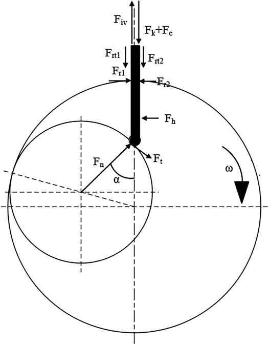
FIGURE 5. Force analysis diagram.
The detailed description about calculation methods is shown in Appendix A.
The friction losses of the rolling rotor expander are listed below:
1) The loss caused by the friction between the main shaft and the bearing L1.
2) The loss caused by the friction between the eccentric wheel and the cylinder end covers L2.
3) The loss caused by the friction between the eccentric wheel and the rolling rotor L3.
4) The loss caused by the friction between the rolling rotor and the upper caps of cylinder L4.
5) The loss caused by the friction between the rolling rotor and the lower end caps of cylinder L5.
6) The loss caused by the friction between the rolling rotor in the first cylinder and the intermediate partition L6.
7) The loss caused by the friction between the rolling rotor in the second cylinder and the intermediate partition L7.
8) The loss caused by the friction between the rolling rotor and the inner wall of cylinder L8.
9) The loss caused by the friction between the slide and the slide grooves L9.
10) The loss caused by the friction between the rolling rotor and the slide L10.
The detailed description about calculation methods is shown in Appendix A.
External leakage and internal leakage exist in the actual working process of the expander. External leakage refers to the leakage of the internal working fluid of the expander to the external environment, and internal leakage refers to the leakage of the working fluid from the high-pressure side inside the expander to the low-pressure side. Because the back pressure of the small fully enclosed rotor expander is high pressure, there is no external leakage. The main internal leakages are shown in Figure 6.
1) The leakage loss through the gap between the end cover of the slide and the cylinder LL1.
2) The leakage loss through the gap between the rolling rotor outer surface and the cylinder inner wall of the cut point LL2.
3) The leakage loss through the gap between the rolling rotor and the cylinder end covers LL3.
4) The leakage loss through the gap between the slide and the slide groove LL4.

FIGURE 6. Internal leakages.
The detailed description about calculation methods is shown in Appendix.
In addition to friction loss and leakage loss, there are also pressure drop and clearance loss in the connecting holes of the intermediate partition. In order to simplify the calculation, the heat exchange between the working fluid and the environment and the heat exchange between the working fluid and the lubricating oil leaking into the cylinder are ignored.
The formula for calculating the efficiency of the expander is:
The expander has been produced. Main constructional parameters of the expander are shown in Table 1. The present model is compared with the experimental data, as shown in Table 2.
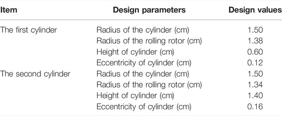
TABLE 1. Main constructional parameters of the expander.
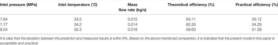
TABLE 2. Comparisons of the theoretical efficiency and practical efficiency.
The back pressure of previously designed expanders is atmospheric pressure or low back pressure (Jiang et al., 2013; Zhao et al., 2014; Hu et al., 2015). The pressure in the expansion chamber is higher than the back pressure, thus making a serious external leakage situation, as shown in Figure 7(Hu et al., 2015). In order to solve this problem, the small fully-enclosed double-cylinder rotor expander introduces the high-pressure working fluid in the compressor into the expander. Thus, the pressure in the expansion chamber is lower than the back pressure, avoiding external leakage loss.
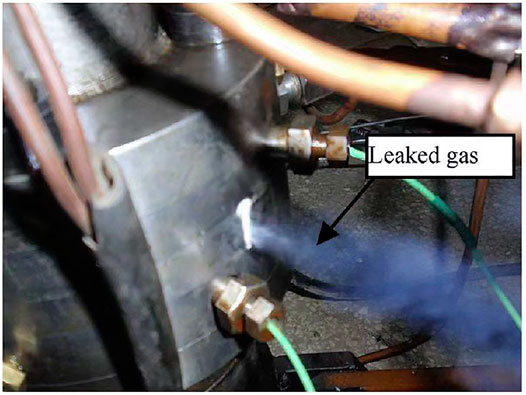
FIGURE 7. Leakage of the expander.
In addition to the leakage losses, back pressure also affects the friction losses. When the back pressure is the suction pressure, the discharge pressure and the atmospheric pressure, the effect of back pressure on the friction force is shown in Figure 8. The high back pressure is 10 MPa and the low back pressure is 4 MPa. The sudden turning point is the suction angle of the first cylinder and the exhaust angle of the second cylinder. At this time, the pressure in the cylinder changes significantly, so the turning point occurs. It can be found that when the back pressure is high pressure, the positive pressure between the sliding plate and the roller of the first cylinder is much smaller than that when the back pressure is atmospheric pressure and the back pressure is low pressure. Although under the partial angle of the second cylinder, when the back pressure is high pressure, the positive pressure between the sliding plate and the roller is greater than that when the back pressure is atmospheric pressure. On the whole, the positive pressure in the high back pressure condition is still lower. When the back pressure is low pressure, the positive pressure is the lowest. The change of friction between the slide and the roller is consistent with the change of the positive pressure. This is because when the back pressure is low pressure, the difference between the pressure inside the expansion chamber and the pressure outside the expansion chamber is the lowest, and the back pressure is high pressure next. When the back pressure is atmospheric pressure, the difference between the pressure inside the expansion chamber and the pressure outside the expansion chamber is the highest. Also, when the back pressure is high pressure, the friction force between the sliding plate and the sliding plate groove is much smaller than that when the back pressure is atmospheric pressure and the back pressure is low pressure. This is because, when the back pressure is high pressure, the positive pressure between the sliding plate and the sliding plate groove is the smallest, and the friction loss is the smallest. Therefore, when the back pressure of the expander is high, not only the leakage loss of the expander can be reduced, but also the friction loss of the expander can be reduced, thereby improving the efficiency of the expander.
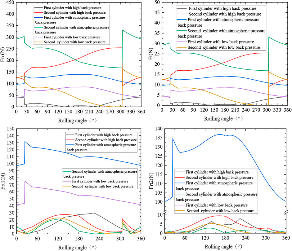
FIGURE 8. Friction under different back pressures.
The volume of the working chamber is determined as follow:
The relative cylinder height λ is the ratio of the cylinder height to the cylinder diameter:
The relative eccentricity is the ratio of the eccentricity to the cylinder radius:
When the volume of the expansion chamber is constant, the structure size of the expander is mainly affected by the relative eccentricity ψ and the relative cylinder height λ. The effects of relative eccentricity and relative cylinder height on expander efficiency are shown in Figure 9.
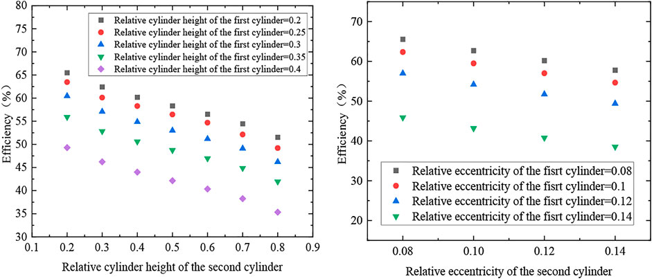
FIGURE 9. Effect of relative cylinder height and relative eccentricity on expander efficiency.
It can be found that the smaller the relative cylinder height of the two cylinders is, the higher the efficiency of the expander is. This is because the relative height of the cylinder affects the force characteristics and leakage loss. If λ increases, the force on the rolling rotor and the sliding plate will increase. The length of the leakage gap and the friction area between the rolling rotor and the sliding plate will increase, which will worsen the stress condition of the compressor and increase the leakage loss and friction loss. However, λ should not be too small. If λ is too small, the diameter of the cylinder will be greatly increased, that is, the radial dimension is too large, which is unreasonable in structure. When Vs and ψ are constant, λ increases, causing the radial dimension R to decrease, which brings certain difficulties to the installation of the intake pipe and the exhaust pipe. When Vs and R are constant, λ increases, causing ψ to decrease, so that the utilization rate of the cylinder volume is reduced.
At the same time, the relative cylinder height of the first cylinder should be smaller than that of the second cylinder. This is because the process carried out in the first cylinder is mainly suction process. The size of the first cylinder has a great influence on the size of the suction volume. The process carried out in the second cylinder is mainly expansion process and exhaust process. The volume after expansion is greater than the suction volume, so the volume of the second cylinder should be larger than that of the first cylinder. In the actual design and manufacture, in order to facilitate manufacture and ensure size coordination, the cylinder diameter of the first cylinder and the second cylinder shall be consistent. Thus, the relative cylinder height of the second cylinder should be greater than that of the first cylinder. Considering the structure and the efficiency of the expander comprehensively, the relative cylinder height of the first cylinder should be 0.2–0.3, and the relative cylinder height of the second cylinder should be 0.4–0.6.
The relative eccentricity has a great influence on the structural size and the utilization rate of the cylinder volume. The cylinder volume utilization factor is defined as:
The larger the ψ is, the higher the utilization rate of the cylinder volume is. From the perspective of improving the utilization rate of the cylinder volume and reducing the volume and weight of the compressor, the relative eccentricity ψ should be selected as a larger value. However, if the value of ψ is too large, as the eccentricity increases, there are more difficulties in structural design. Ultimately, the reliability and efficiency of the expander are reduced. Considering the cylinder volume utilization rate and expander efficiency comprehensively, the relative eccentricity should be around 0.1.
The intermediate partition plays the role of separating the first cylinder and the second cylinder, connecting the exhaust hole of the first cylinder and the intake hole of the second cylinder. The residual working fluid in the intermediate partition cannot expand effectively, resulting in clearance loss. At the same time, there is a pressure drop in the connecting hole. Figure 10 shows the effect of the thickness of the intermediate partition and the diameter of the connecting hole on the expander. It can be found that the smaller the diameter of the connecting hole is, the larger the pressure drop and the smaller the clearance loss is. When the diameter of the connecting hole is too small, the pressure drop will be too large, which will affect the performance and stability of the expander. The diameter of the connecting hole should be 5 ∼6 mm. The length of intermediate partition has little effect on the pressure drop. When the length is shorter, the clearance loss is smaller. If the length of the intermediate partition is too short, the heat insulation is poor, and the heat of the first cylinder will be transferred to the second cylinder through, which will affect the efficiency. The thickness of the intermediate partition should be 4∼6 mm.
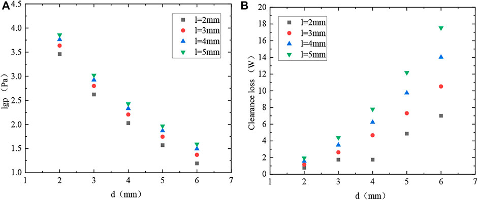
FIGURE 10. The influence of the intermediate partition. (A) Influence on pressure drop. (B) Influence on clearance loss.
The change of friction loss with the rolling angle is shown in Figure 11. The back pressure is assumed as 10 MPa. It can be found that the loss caused by the friction between the slide and the slide grooves and the loss caused by the friction between the rolling rotor and the slide is the main friction loss of the expander. Among them, the friction loss value of the second cylinder is rather larger than that of the first cylinder. This is because the difference between the pressure inside the expansion chamber of the second cylinder and the pressure outside the expansion chamber is higher than that of the first cylinder, as shown in Figure 8. The frictional force of the second cylinder is far greater than that of the first cylinder.

FIGURE 11. Variation of friction loss with rolling angle.
The change of leakage loss with the rolling angle is shown in Figure 12. The back pressure is assumed as 10 MPa. It can be found that the leakage loss through the gap between the rolling rotor and the cylinder end covers is the most important loss. The size of the leakage loss is directly related to the size of the gap. The contact gap between the roller end face and the cylinder end cover, the roller end face and the intermediate partition can be reduced by means of surface coating.

FIGURE 12. Variation of leakage loss with rolling angle.
The expander efficiency is also affected by the inlet state, mainly the mass flow rate, inlet temperature and inlet pressure, as shown in Figure 13. The value of the back pressure is the same as the inlet pressure. It can be found that for the expander with a certain volume, there is a peak mass flow rate, when the expander efficiency reaches the maximum value. This is because when the mass flow rate increases, the rotating speed and the expansion work also increase. But at the same time, the energy loss is also increasing.
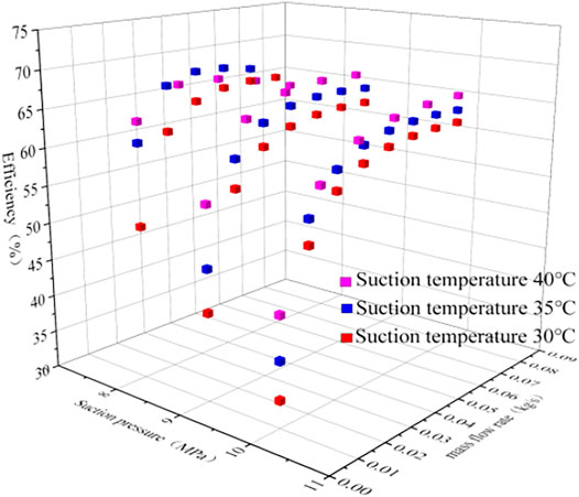
FIGURE 13. Effect of inlet state on expander efficiency.
The efficiency of the expander decreases as the suction pressure increases. This is because, although theoretically, large inlet pressure is conducive to the acceleration of the rotating speed. The pressure difference between the pressure in the expansion chamber and the pressure outside the expansion chamber is also increasing, and the friction loss increases. At the same time, under the larger inlet pressure, the pressure difference on both sides of the roller increases, and the leakage loss increases.
The efficiency of the expander increasing with increasing inlet temperature. When the outlet temperature of the gas cooler is higher, the throttling loss of the CO2 system is rather large, and the CO2 system efficiency is very low. Meantime, the efficiency of the expander is greatly high, which has a significant effect on improving the system efficiency.
The use of expander is an effective measure to improve the efficiency of CO2 household air-conditioning systems. In this paper, a fully enclosed double-cylinder CO2 rotor expander was designed, and its structure and working process were introduced. Besides, the factors affecting the efficiency of the expander were studied by the method theoretical analysis, which provides theoretical support for the design and manufacture of the expander. The main conclusions are as following:
1) When the back pressure is the atmospheric pressure or low back pressure, the external leakage loss is serious. The design of high back pressure can avoid external leakage loss, and reduce friction loss. At this time, the positive pressure between the sliding plate and the sliding plate groove is the smallest.
2) The relative cylinder height of the first cylinder should be smaller than that of the second cylinder. Considering the structure and the efficiency of the expander comprehensively, the relative cylinder height of the first cylinder should be 0.2–0.3, and the relative cylinder height of the second cylinder should be 0.4–0.6. The relative eccentricity should be around 0.1.
3) In order to reduce the clearance loss while maintaining a small pressure drop, the connecting hole should be limited between 5 and 6 mm. To ensure thermal insulation while reducing the clearance loss, the thickness of the intermediate partition should be 4∼6 mm.
4) The loss caused by the friction between the slide and the slide grooves and the loss caused by the friction between the rolling rotor and the slide are the main friction losses of the expander. And the main leakage loss is the loss through the gap between the rolling rotor and the cylinder end covers.
5) There is s peak mass flow rate, when efficiency reaches the maximum value. The efficiency of the expander decreases as the suction pressure increases. In the condition when the outlet temperature of the gas cooler is relatively high, the expander will play an increasingly important role.
The original contributions presented in the study are included in the article/Supplementary Material, further inquiries can be directed to the corresponding author.
PW: Design the expander structure and calculate the expander efficiency. ML: Make important changes to the paper. YM: Make important changes to the paper. HT: Make important changes to the paper. BH: Draw diagrams.
This work was supported by the National Key Research and Development Program of China (2021YFF0306801), Chinese Association of Refrigeration (CAR20190701).
The authors declare that the research was conducted in the absence of any commercial or financial relationships that could be construed as a potential conflict of interest.
All claims expressed in this article are solely those of the authors and do not necessarily represent those of their affiliated organizations, or those of the publisher, the editors and the reviewers. Any product that may be evaluated in this article, or claim that may be made by its manufacturer, is not guaranteed or endorsed by the publisher.
This work was supported by the National Key Research and Development Program of China (2021YFF0306801), Chinese Association of Refrigeration (CAR20190701).
Abas, N., Kalair, A. R., Khan, N., Haider, A., Saleem, Z., and Saleem, M. S. (2018). Natural and Synthetic Refrigerants, Global Warming: A Review. Renew. Sustain. Energy Rev. 90, 557–569. doi:10.1016/j.rser.2018.03.099
Cui, C., Ren, J., Song, Y., Yin, X., Wang, W., Yang, X., et al. (2021). Multi-variable Extreme Seeking Control for Efficient Operation of Sub-cooler Vapor Injection Trans-critical CO2 Heat Pump Water Heater. Appl. Therm. Eng. 184, 116261. doi:10.1016/j.applthermaleng.2020.116261
Ferrara, G., Ferrari, L., Fiaschi, D., Galoppi, G., Karellas, S., Secchi, R., et al. (2016). Energy Recovery by Means of a Radial Piston Expander in a CO2 Refrigeration System. Int. J. Refrig. 72, 147–155. doi:10.1016/j.ijrefrig.2016.07.014
Haiqing, G., Yitai, M., and Minxia, L. (2006). Some Design Features of CO2 Swing Piston Expander. Appl. Therm. Eng. 26 (2), 237–243. doi:10.1016/j.applthermaleng.2005.05.011
Heredia-Aricapa, Y., Belman-Flores, J. M., Mota-Babiloni, A., Serrano-Arellano, J., and García-Pabón, J. J. (2020). Overview of Low GWP Mixtures for the Replacement of HFC Refrigerants: R134a, R404A and R410A. Int. J. Refrig. 111, 113–123. doi:10.1016/j.ijrefrig.2019.11.012
Hu, J., Li, M., Zhao, L., Xia, B., and Ma, Y. (2015). Improvement and Experimental Research of CO2 Two-Rolling Piston Expander. Energy 93, 2199–2207. doi:10.1016/j.energy.2015.10.097
Jiang, Y., Ma, Y., Fu, L., and Li, M. (2013). Some Design Features of CO2 Two-Rolling Piston Expander. Energy 55, 916–924. doi:10.1016/j.energy.2013.03.053
Jiang, Y. (2009). Study on CO2 Transcritical Water-Water Heat Pump and Two Cylinder Rolling Piston Expander. China: Tianjin University.
Li, Y., Li, M., Hu, Y., Xu, J., and Ren, L. (2022). Researches on Leakage with Lubricating Oil Using a Composite Multiphase Lattice Boltzmann Method. Therm. Sci. 26 (1), 221–231. doi:10.2298/tsci200605135l
Li, Y. (2019). Simulations and Optimizations for Leakages in CO2 Expanders Based on LBM. China: Tianjin University.
Lorentzen, G. (1994). Revival of Carbon Dioxide as a Refrigerant. Int. J. Refrig. 17 (5), 292–301. doi:10.1016/0140-7007(94)90059-0
Luo, J., Yang, K., Zhao, Z., Chen, G., and Wang, Q. (2022). Experimental Investigations on the Performance of a Single-Stage Compound Air-Source Heat Pump Using CO2/R600a in Cold Regions. Appl. Therm. Eng. 205, 118050. doi:10.1016/j.applthermaleng.2022.118050
Qin, X., Zhang, Y., Wang, D., and Chen, J. (2022). System Development and Simulation Investigation on a Novel Compression/ejection Transcritical CO2 Heat Pump System for Simultaneous Cooling and Heating. Energy Convers. Manag. 259, 115579. doi:10.1016/j.enconman.2022.115579
Wang, J., Belusko, M., Liu, M., Semsarilar, H., Liddle, R., Alemu, A., et al. (2021). A Comprehensive Study on a Novel Transcritical CO2 Heat Pump for Simultaneous Space Heating and Cooling - Concepts and Initial Performance. Energy Convers. Manag. 243, 114397. doi:10.1016/j.enconman.2021.114397
Wang, W. (2009). Structure Improvement and Experimental Study on CO2 Double Rolling Piston Expander. China: Tianjin University.
Wei, D. (2002). Study on the Heat Transfer and Expansion Mechanism of Carbon Dioxide Transcritical Cycle. China: Tianjin University.
Yang, B., Peng, X., He, Z., Guo, B., and Xing, Z. (2009). Experimental Investigation on the Internal Working Process of a CO2 Rotary Vane Expander. Appl. Therm. Eng. 29 (11), 2289–2296. doi:10.1016/j.applthermaleng.2008.11.023
Zhang, B., Peng, X., He, Z., Xing, Z., and Shu, P. (2007). Development of a Double Acting Free Piston Expander for Power Recovery in Transcritical CO2 Cycle. Appl. Therm. Eng. 27 (8), 1629–1636. doi:10.1016/j.applthermaleng.2006.05.034
Zhao, L., Li, M., Ma, Y., Liu, Z., and Zhang, Z. (2014). Simulation Analysis of a Two-Rolling Piston Expander Replacing a Throttling Valve in a Refrigeration and Heat Pump System. Appl. Therm. Eng. 66 (1), 383–394. doi:10.1016/j.applthermaleng.2014.01.055
Zhao, L. (2014). The Theoritical and Experimental Research on Expansion Device in Refrigeration and Heat Pump Systems. China: Tianjin University.
m mass flow rate, kg/s
hin inlet enthalpy of expander, J/kg
hout outlet enthalpy of expander, J/kg
Wmiddle loss in the intermediate partition, W
Wideal ideal work, W
Vs suction volume, m3
R expander cylinder radius, m
r rolling rotor radius, m
H height, m
e eccentricity, m
K cylinder volume utilization factor
P pressure, Pa
l length of intermediate partition, m
d channel diameter, m
Abbreviations
HCFC hydrochlorofluorocarbons
CFC chlorofluorocarbon
COP coefficient of performance
Greek letters
Subscript
1 the first cylinder
2 the second cylinder
Keywords: expander, CO2, double-cylinder, totally enclosed, air-conditioner
Citation: Wang P, Li M, Ma Y, Tian H and Hou B (2022) Analysis of Influencing Factors of a Fully Enclosed Double-Cylinder CO2 Rotor Expander for Air-Conditioner. Front. Energy Res. 10:956807. doi: 10.3389/fenrg.2022.956807
Received: 30 May 2022; Accepted: 08 June 2022;
Published: 08 July 2022.
Edited by:
Baomin Dai, Tianjin University of Commerce, ChinaReviewed by:
Xin Cui, Xi’an Jiaotong University, ChinaCopyright © 2022 Wang, Li, Ma, Tian and Hou. This is an open-access article distributed under the terms of the Creative Commons Attribution License (CC BY). The use, distribution or reproduction in other forums is permitted, provided the original author(s) and the copyright owner(s) are credited and that the original publication in this journal is cited, in accordance with accepted academic practice. No use, distribution or reproduction is permitted which does not comply with these terms.
*Correspondence: Minxia Li, dGpteGxpQHRqdS5lZHUuY24=
Disclaimer: All claims expressed in this article are solely those of the authors and do not necessarily represent those of their affiliated organizations, or those of the publisher, the editors and the reviewers. Any product that may be evaluated in this article or claim that may be made by its manufacturer is not guaranteed or endorsed by the publisher.
Research integrity at Frontiers
Learn more about the work of our research integrity team to safeguard the quality of each article we publish.