- 1School of Mechanical Engineering, Nanjing Institute of Technology, Nanjing, China
- 2Haitian Plastics Machinery Group Co., Ltd., Ningbo, China
- 3College of Water Conservancy and Hydropower Engineering, Hohai University, Nanjing, China
Pipe vibration induced by water hammer frequently emerges in water conveyance system, especially in the hydropower plant or pumped storage power station with long diversion pipelines. This vibration in turn affects the hydraulic pulsation so that undesired fluid-structure interaction (FSI) arises. In this research, attention is given to a pipeline embedded in concrete. A six-equation model was derived to describe the fluid-pipe-concrete interaction considering Poisson coupling and junction coupling. With the elastic and homogeneous hypotheses, an iterative approach was proposed to solve this model, and the results were validated by experiment and classical water-hammer theory. Then dynamic FSI responses to water hammer were studied in a reservoir-pipe-valve physical system. Hydraulic pressure, pipe wall stress and axial motion were discussed with respect to different parameters of concrete. Results obtained by the two-equation model, four-equation model and six-equation model show characteristics of pressure wave and stress wave separately with and without FSI.
1 Introduction
Water conveyance pipeline has been widely used in marine engineering, petrochemical engineering, energy and power engineering, spacecraft power system and also daily life. Repeated stimuli inside and outside the pipeline have been proven to excite pulsations in the pressurized fluid. Water hammer is a typical trigger frequently inducing structural vibration and new pressure fluctuations. This fluctuation further causes pipe expansion or contraction, which in turn affects the hydraulic pressure inside the pipe. This phenomenon is the typical fluid-structure interaction (FSI). However, FSI responses closely depend on the operating condition of the pipe system. Hence, FSI analysis should be carried out according to various constraints and boundary conditions (Mahmoodi, et al., 2019; Tijsseling, 2019; Rajbamshi, et al., 2020).
Friction coupling, Poisson coupling and Junction coupling are three main types when pipeline interacts with fluid. The first two emerge throughout the whole pipeline, whereas Junction coupling only happens in local positions including the elbows, branches, valves, boundaries, and variable cross-sections (Zanganeh, et al., 2015). System coupling in these locations becomes stronger (Alaei, et al., 2019). Furthermore, response to friction coupling is the weakest and has a long duration of oscillation (Huang and Alben, 2016). As the most important coupling form, Junction coupling depends on the robustness of the system and usually causes a pressure head larger than the classical water hammer (Karakouzian, et al., 2019). Poisson coupling and friction coupling can greatly influence Junction coupling. And in turn, Junction coupling has a greater impact on the pipeline system compared with Poisson coupling.
Regarding the constraints of pipeline, Li, et al. (2012) and Liu and Li. (2011) analyzed the elastic support and found the complex boundary conditions can be successfully simulated by the six-equation elastic spring model. Then, Li, et al. (2014) expanded the application of this elastic model. The FSI is continuously induced and transmitted in fluids and pipelines. This interaction becomes much stronger in pipes with few or no support (Liu and Li. 2011). Meanwhile, FSI has a crucial effect on fluid pressure and pipe stress when the pipe axial stiffness is greater than the rigidity of the supports (Li, et al., 2012). In a typical case study, Riedelmeier (Riedelmeier, et al., 2014) analyzed FSI phenomenon under four kinds of axial support and determined proper support to mitigate the displacement and stress in pipes.
The preceding achievements mainly focused on the FSI response of water conveyance systems with various pipeline layouts. Notably, the external constraints of pipes were generally discrete and their effects on FSI response were simplified as boundary conditions. For example, a pipe with continuity constraints degenerates into a multi-span pipeline model (Wu and Shih, 2001; Yang, et al., 2004). This simplification omits the global restriction of the constraint as well as its vibration. So the current model available in the literature is yet to be completely suitable. Herein, this paper investigates the constraints and dynamic responses in a water conveyance pipeline surrounded by concrete, focusing on fluid-pipe-concrete interaction. Pipe and concrete are integrated as a composite structure in this research, similar to that in a pre-stressed concrete cylinder pipe (PCCP) (Lee, et al., 2012; Hu, et al., 2019; Sun, et al., 2020). Compared to the typical FSI, FSI arising in such a system contains an extra pipe-concrete interaction. However, this extra effect is yet to be included in the current PCCP model.
A typical reservoir-pipe-valve system is used in this paper to produce water hammer. With the simplified elastic model of concrete, as well as continuity and motion equations of fluid, pipe and concrete, the fluid-pipe-concrete six-equation model is derived. Then an iterative approach is proposed to solve this model and the results get validated by experiment. Dynamic responses concerning the fluid-pipe-concrete interaction of the reservoir-pipe-valve system are subsequently scrutinized, including hydraulic pressure, pipe wall stress and vibration.
2 Numerical Model
When water conveyance system with a straight pipe suffers from water hammer, the axial structural vibration becomes obvious. In the fluid-pipe-concrete model, system characteristics can be described by solid constitutive equations and fluid governing equations. Then the FSI in such a composite structure is mathematically deduced. Two global hypotheses should be followed.
• The axial component of parameters in the control volume is equivalent to the average value in the corresponding section (Ting, et al., 2017).
• Axial stress, strain and displacement are separately assumed to be constant at the radial direction on a certain cross-section.
2.1 Stress at Inner Interface and Outer Interface
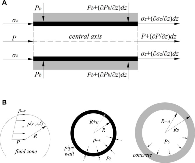
As for a piping system embedded in concrete, the pipe concrete coupling is taken into account. A sketch of stress from concrete imposing on pipe wall is shown in Figure 1. Figure 1A illustrates the external forces applied on an element of pipe wall. In this work, section of the concrete segment is considered to be annular. Then the inner interface is defined by the fluid and pipe wall, while outer interface by the pipe wall and ambient concrete, as seen in Figure 1B.
Since the pipeline is symmetric, the stress of concrete uniformly distributes around the pipe ring and can be assumed as a function of the radial coordinate (Wu, 2017; Mirjavadi, et al., 2020). By extension, Lame solutions of the radial stress of pipe wall σr, hoop stress of pipe wall σθ, radial stress of concrete σrs and hoop stress of concrete σθs in this encased system are separately presented as follows (Daoxiang and Weinlin, 2006):
where R is the internal diameter of pipe, e is the thickness of pipe wall, Pb and p|r = R are external and internal pressure of pipe wall, separately.
Pipe wall and concrete have the identical radial strain εr|r = R+e on their interface. Due to the assumption of linear radial displacement, εr|r = R+e = εr|r = R. According to Hooke law, εr|r = R+e is defined as:
where σz is the axial stress of pipe wall, E is the elastic modulus of pipe wall, and ν is the Poisson’s ratio of pipe wall.
According to the reference (Sinha, et al., 2001) in a concrete-encased piping system, the concrete strain is small enough so that the stress-strain relation degenerates into an elastic model, shown as:
where σzs is the concrete axial stress because of expansion or contraction of the outer pipe wall. Pb is the constant pressure imposed on the outer pipe wall by ambient concrete, thus, Pb = σrs|r = R+e. νs and Es are the Poisson’s ratio and elastic modulus of concrete, separately.
Recalling linear displacement at the radial direction and substituting Eqs 1–4 into Eq. 5, yields the radial stress on the outer interface:
The fluid radial velocity component Vr is assumed to be constant at a certain section. So Vr is equal to the radial velocity of pipe ur on the inner interface (Lai, et al., 2020). Then pressure relationship with respect to pipe center-line and inner interface is established:
where P is the pressure at the pipe center line. ρf is the fluid density. And radial motion equation of pipeline is defined as:
where ρt is the density of pipe wall material. Substitute Eq. 1 into Eq. 8:
The following can be obtained by solving Eqs 6, 7, Eq. 9.
The definition of coefficients a, b, c, d, f and h can be seen in the Appendix.
2.2 Governing Equations for Fluid
2.2.1 Axial Motion Equation of Incompressible Flow
The equation of axial motion of fluid at pipe centerline is:
where t and z are time and axial direction respectively. V is the fluid velocity at pipe centerline. Af is the area of the flow section. The total acceleration of fluid is composed of the convective acceleration and the local one. So Eq. 12 can be converted to:
The one-dimensional axial motion equation of fluid at pipe centerline is obtained.
2.2.2 Continuity Equation of Incompressible Flow
Ignoring the hoop velocity of the pipe, continuity equation of the symmetric flow can be expressed in cylindrical coordinate:
Recalling the definition of fluid bulk modulus K, ∂P/∂ρf = K/ρf, Eq. 15 is converted to:
Averaging over the cross-section, a continuity equation of one-dimensional flow is derived as (Tijsseling, 2007):
The Resultant Equation Is:
Substituting Eqs 1, 2 into Eq. 19:
Substituting Eqs 10, 11, into Eq. 20:
in which
Substituting Eq. 21 Into Eq. 18:
2.3 Governing Equations for Pipe
2.3.1 Axial Motion Equation of Structures
For pipe walls, the axial external force is the shear force. Considering pipe-concrete coupling, the motion equation of the pipe is:
where uz and σz are axial velocity and axial stress of pipe, At is the cross-sectional area of the pipe wall. G = E/2(1+νs) is the shear modulus of elasticity of concrete. The axial strain of concrete εs = ∂ws/∂z. ws is the axial displacement of concrete.
Eq. 23 is then Simplified:
Due to the concrete axial velocity us = ∂ws/∂t, Eq. 24 is updated.
2.3.2 Pipeline Continuity Equation
According to the Hooke law, the strain-stress relation applied to pipe axial direction is:
where wz is the axial displacement of pipe wall and uz = ∂wz/∂t. According to Eqs 1, 2, the sum of radial and hoop mean stresses is:
For convenience, Eq. 27 is written as:
in which
Substituting Eq. 28 into Eq. 26:
2.4 Governing Equations for Concrete
Considering structural vibration caused by FSI, the axial motion equation of concrete is:
where ρs and As are density and sectional area of concrete, respectively. Eq. 30 can be simplified.
According to Hooke law, the strain-stress relation of concrete is:
Taking time derivative of Eq. 32:
Based on Eq. 3, the sum of radial and hoop mean stresses can be expanded as:
Then substituting Eq. 34 into Eq. 33:
Till now, a six-equation model describing the fluid-pipe-concrete system is derived. This model consists of continuity and motion equations of fluid and pipe, and constitutive equations of concrete. And these equations are coupled by the boundary conditions on their interfaces, at r = R and r = R + e.
3 Solution Methodology
3.1 Finite Volume Discretization
The finite volume method (FVM) can provide satisfactory predictions to flow transients by solving equations in each control volume (Ferras, et al., 2017) and by presenting each physical term in integral form (Cardiff, et al., 2016). Based on cell-centered FV discretization, an iterative approach is proposed in this paper to calculate the FSI responses. As shown in Figure 2A, the control volume includes two dimensions, namely the time step ΔT and the control volume length ΔZ. The model is solved at the center of each cell. In order to numerically keep higher accuracy, the discretization grids system is shown in Figure 2B, where ΔZ = 2Δz and ΔT = 2Δt.

FIGURE 2. Discretization grids system (A) Cell-centered form of FVM. (B) An equivalent grid system of A.
This method discretizes Eq. 14 and Eq. 22, Eq. 25, Eq. 29, Eq. 31 and Eq. 35 using the control volume and integrates differential equations from t to t + Δt in each control volume. The generalized differential equation can be expressed as:
The Crank-Nicolson implicit form of time-centered difference provides a second-order accuracy to predict the partial differential terms. And unconditional stability is guaranteed with respect to the solution process (Ramírez, et al., 2018).
where Q denotes the state matrix in each control volume at each time step.
A, B and S are shown in the Appendix. n denotes the nth time step. i is the ith calculation nodes. Δt denotes the time step. Δz denotes the axial interval of each node.
According to Eqs 37–40, the iterative matrix between adjacent time steps for the water conveyance system is built as follows:
in which
Vector Ci and Qi separately denote the state vector in the ith node at the nth and (n+1)th time step. i = 1 to N, where 1 and N refer to the inlet and outlet of the pipeline, respectively. When discontinuity happens between adjacent pipelines or fluid, this discontinuous section will be modeled as an interior boundary condition. Ai and Ci are included in the following equations of boundary conditions.
3.2 Boundary Conditions
Given that the cross-sectional area of the reservoir is much larger than that of the pipeline, the water level in the tank can be treated as a constant (Vardy et al., 1996):
where P0 denotes the pressure provided by the water level in the reservoir. The pipe inlet and outlet are rigidly connected to the system respectively, so the corresponding continuity equations of axial direction are as follows (De Santis and Shams, 2019):
When the outlet valve is closed, fluid flow velocity, axial velocity of the pipe wall and discharge satisfy:
where τ = (1—t/Tc)1.5, τ is the closing coefficient which gradually changes from 1 to 0 when the valve is closed. Tc is the total shutdown time. Subscript 0 denotes the initial value.
4 Method Validation
4.1 Experimental Data Comparison
A more general apparatus proposed by Vardy and Fan is used for benchmark purposes, as seen in Figure 3 (Vardy et al., 1996). This system consists of a single pipe of 4.5 m and a rod of 5.006 m. The pipe is suspended and kept horizontal by long wires. Both ends of it are sealed by steel caps. And the pipe contains pressurized water to prevent cavitation. Then the steel rod axially impacts the stationary pipe to generate waves in the fluid and in the pipe.
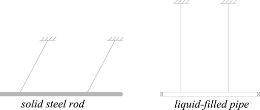
FIGURE 3. Experimental apparatus (Vardy et al., 1996).
This system during transients is solved by the six-equation model and the iterative methodology. Herein, the pipe is regarded as a thin-wall pipe encased in the same material (ρt = ρs, ν = νs, E = Es). The corresponding cross-section is similar to the sketch in Figure 1B.
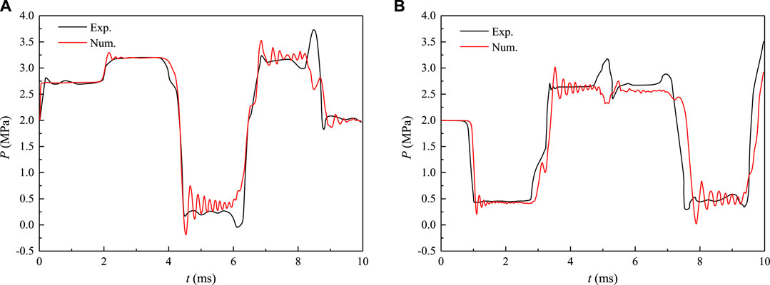
Results from the experiment and numerical iteration are presented in Figure 4, including pressure fluctuations at the impact end (Figure 4A) and at the remote end (Figure 4B) of the pipe. The time step in the numerical calculation is 10−4 s to ensure this algorithm can capture the high-frequency fluctuation. While in the test, the max sampling frequency is 80 Hz. So the black curve in Figure 4 is relatively smooth compared to the red line. The latter one contains more fluctuating features. In Figure 4A, pressure values at the first peak are 2.82 MPa for experiment and 2.74 MPa for simulation. The relative error is 2.84%. Moreover, this six-equation model mainly takes axial coupling and radial coupling into account, while failing to include torsion coupling. Due to experimental error, the discrepancy between the two curves is acceptable. Generally, numerical results are in good agreement with the experimental data. This reveals this numerical model is suitable to investigate the dynamics and kinematics of the piping system embedded in concrete. And the FV discretization method is feasible to solve this system.
4.2 Classical Model Comparison
A typical reservoir-pipe-valve system is built up with pipe length L = 10 m, R = 0.1 m, e = 0.01 m. Figure 5 sketches this system encased in concrete.
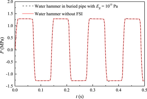
In this system, the water hammer induced by closing the valve was separately calculated by the classical two-equation model and the six-equation model established in this paper. As seen in Figure 6, little deviation arises between these two models when ES = 1015 Pa. The two-equation model neglects fluid-pipe interaction based on the classical water hammer theory. With respect to the six-equation model, the elastic modulus of concrete is large enough so that the pipe vibration is negligible and the FSI response is weak. In such a case, the six-equation model degenerates to the classical model and their results are almost identical.
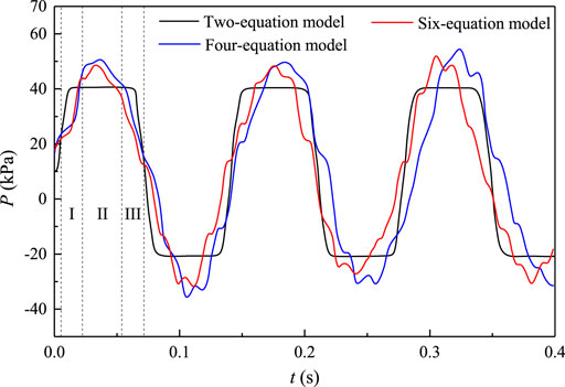
To further justify the derived six-equation model, comparisons to the two-equation model, and four-equation model are discussed with respect to the water hammer in a typical reservoir-pipe-valve system. The pressure fluctuations upstream the valve by these models are illustrated in Figure 7. The two-equation model omits the FSI, so the pressure curve is trapezoidal waveform in shape. The four-equation model involves fluid-pipe interaction but neglects constraints on the pipe’s outer surface. This is equivalent to an exposed pipe system.
The peak segment of the black line in Figure 7 can be split into three parts. In region I, the red and blue lines are lower than the black line due to pipe expansion at the valve. In region II, red and blue lines climb over the black line. Because in FSI-involved models, contraction of the pipe wall plays pumping effects on fluid, triggering a larger pressure than the classical result. In region III, the axial stress wave bounces back, expands again the pipe and results in the last pressure drop over the pressure surge. Moreover, an exposed pipe (four-equation model) has a smaller pressure wave speed, but stronger FSI responses due to less support. When the pipe is embedded into concrete, constraints weaken the contributions of the pumping effect. Peak pressure is suppressed, shown as the red line lower than the blue one. When the stiffness of the concrete is large enough, peak pressure and pressure wave speed are similar to those in the classical model, as shown in Figure 6.
5 Results and Discussions
This section deals with the kinematic and dynamic characteristics based on the layout in Figure 5 when the fluid-pipe-concrete interaction is taken into account. Hydraulic transients is triggered by closing the valve in 0.01 s. And the closing law depends on the coefficient τ in Eq. 44.
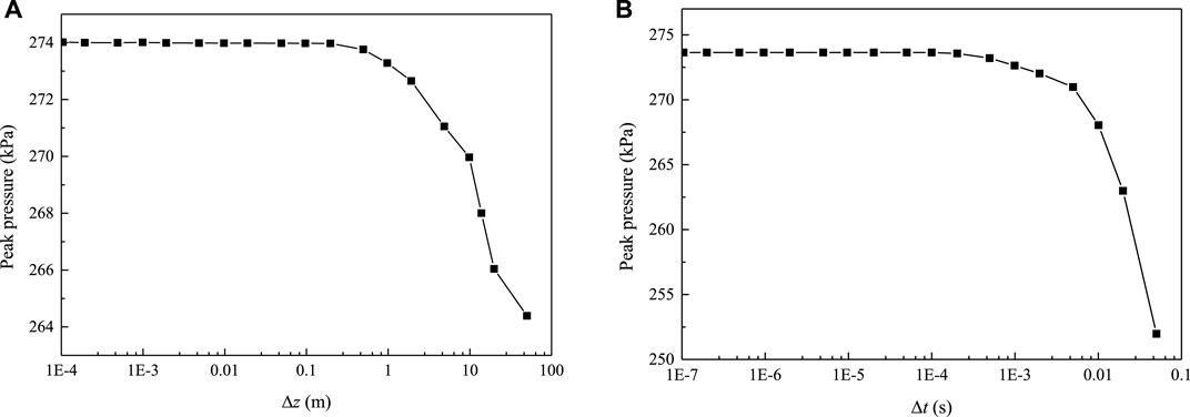
Sensitive analysis of grid size and time step is first discussed, which determines the result precision. In this process, the Courant number is well controlled to ensure a stable iteration and reliable results. Numerical results of peak pressure vary with these two parameters are given in Figure 8. When Δz > 0.1 m in Figure 8A, the peak pressure drops dramatically with the increase of grid interval. On the contrary, if Δz < 0.1 m, the numerical result is not sensitive to grid size. Figure 8B shows a similar manner when the threshold value of the time step is 10−4 s. Consequently, the node interval and time step are separately set to be 0.1 m and 10−4 s in the iterative algorithm.
5.1 Influence of Concrete on Hydraulic Pressure
As known from Eq. 22 and Eq. 31, FSI responses to water hammer greatly depend on parameters of concrete, including its Poisson’s ratio, thickness-radius ratio, elastic modulus and density. Hydraulic pressure upstream the valve fluctuates with these parameters are shown in Figures 9A–D, respectively.
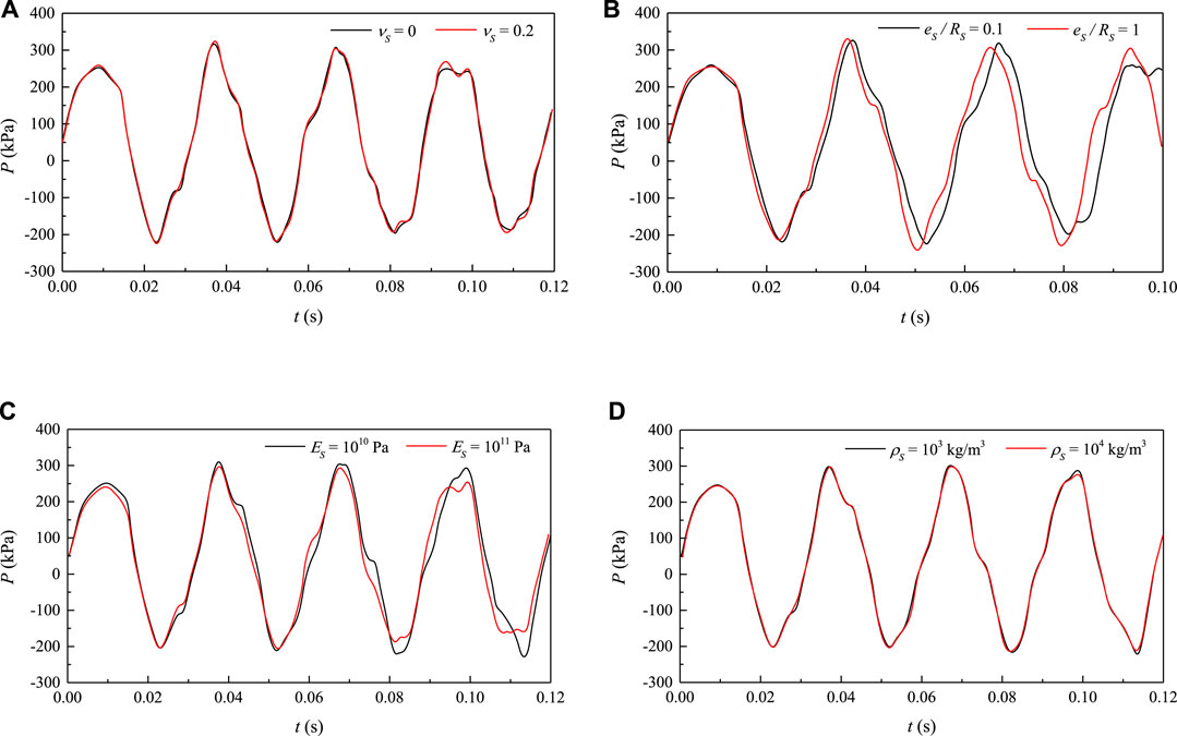
FIGURE 9. Dynamic pressure varies with the parameters of concrete (A) Poisson’s ratio. (B) Thickness-radius ratio. (C) Elastic modulus. (D) Density.
It is clear that the Poisson’s ratio and concrete density hardly affect the hydraulic pressure as the two curves are almost overlapped, as seen in Figures 9A,D. Firstly, coefficients in Eqs 10, 11 are the function of νs from their definitions in the Appendix. But the difference of R⋅p|r=R - (R + e)⋅Pb can be ignorable. Moreover, νs mainly contributes to the axial shear force between concrete and pipe, while little affects the pressure. With respect to the concrete density, ρs only dominates the inertia of concrete, then affects the frictional force on the outer interface. However, hydraulic pressure hardly changes when ρs becomes ten times larger. This reveals that the axial vibration of concrete plays a negligible role in FSI responses.
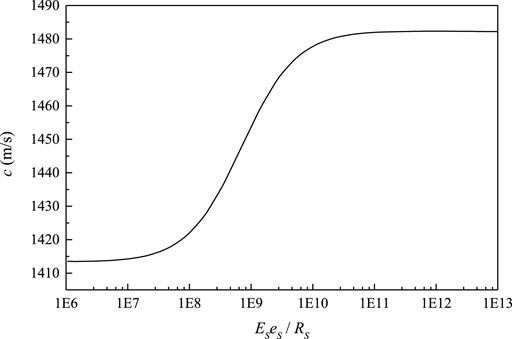
In contrast, the thickness-radius ratio and elastic modulus play an important role in the FSI response. By extension, larger Es alleviates the pumping effect on fluid and further weakens the FSI response. Hydraulic pressure fluctuates more moderately in this case and decays faster, as seen in Figure 9C. Besides, Es and es/Rs both influences the pressure wave speed, then change the fluid inner pressure. Figure 10 shows the wave speed changing with the product of Es and es/Rs.
In the graph when Eses/Rs < 106 Pa, pressure wave speed is almost constant and the pumping effect can be ignored. So the pipe encased in concrete is approximate to an exposed one, and the four-equation model is suitable in this case. When Eses/Rs > 1011 Pa, influences of wave speed and pumping effect are also negligible. In this case, the FSI response is weak, so the two-equation model is suitable. When Eses/Rs increases from 106 Pa to 1011 Pa, the wave speed changes dramatically as well as the FSI responses. Notably, the Eses/Rs of concrete is within this range. Thus, studying the FSI in a piping system embedded in concrete is of great importance.
5.2 Pipe-Wall Stress
In this study, pressure gradients applied to the interface cause pipe wall expansion or contraction, and further compress or relax the ambient concrete. Thus, Pb is produced and subsequently weakens the FSI responses. The dynamic pressure on the inner and the outer interfaces are separately shown in Figures 11A,B.
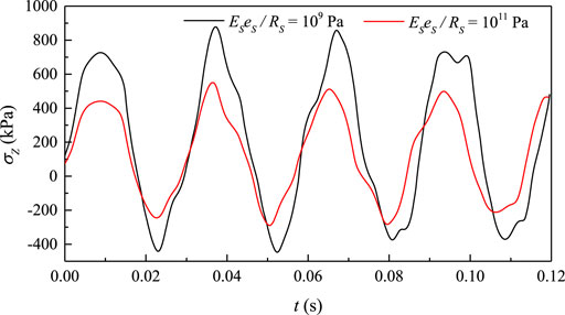
Stronger pulsations are caused by larger Eses/Rs on both inner and outer interfaces. With larger Pb, a weaker pumping effect is obtained. Hoop stress and radial stress of pipe wall become smaller due to restrictions by concrete from Eqs 1, 2. The result is the piping system gets safer. Moreover, the difference between R⋅p|r=R and (R + e)⋅Pb is smaller in the case of larger Eses/Rs, which can further lead to weaker axial stress pulsation in the pipe wall, as shown in Figure 12.
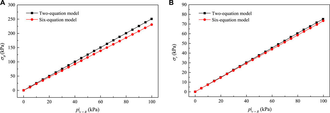
The six-equation model derived in this paper aims to investigate FSI subject to water hammer. Due to the deformation of structures, FSI response to some extent weakens the stress pulsation in the pipe wall. As shown in Figure 13, both the hoop and radial stress are larger using the classical model without FSI.
5.3 Pipe-Wall Motion
In this segment, the axial vibration of the system is analyzed. Axial displacement of the pipe wall relates to the fluid and concrete, while the concrete plays the damping role. Signals of axial displacement in the time domain and frequency domain are shown in Figures 14A,B, separately. When FSI is taken into account, the pipe-wall motion is found to relate to the pressure wave in fluid and stress wave in solid. These two waves propagate throughout the pipeline system in the axial direction, contributing to the vibration amplitude in Figure 14A. In radial direction, pipe expansion or contraction is confined by the ambient concrete, so the radial vibration of the pipe wall is weak.
Pipe vibration is mainly caused by hydraulic pressure fluctuation, especially when FSI is included. All vibration modes in this case are system modes. However, pipe deformation mode can be identified by data processing. The first eight modes of pipe with respect to different models are shown in Table 1. Data in the right column correspond to the local peaks in Figure 14B. According to calculation results, the frequency of pressure wave is 35.2 Hz, the frequency of stress wave in pipe wall is 129.3 Hz, and the frequency of stress wave in concrete is 99.6 Hz.
The two-equation model predicts the highest frequency value at each mode without FSI. Compared with the four-equation model, constraints by concrete enlarges the frequency value in the six-equation model. Wave speed in this model is faster, in accord with the curve tendency in Figure 10. Additionally, Pipe and concrete absorb more energy from water hammers so that FSI responses are alleviated. Similar results are obtained in Figure 7. Comparison of the three models shows that inherent frequency of the piping system is changed when different factors are taken into account, like the concrete. On the other, the pressure surge acts as an unstable source during FSI responses. When parameters of the concrete change, nature frequency of the pressure pulsation is changed accordingly. This situation may lead to undesirable resonance, especially in a more complex pipeline layout.
6 Conclusion
This work studies the FSI responses of a piping system embedded in concrete during water hammers. Based on area average treatment on a cross-section, a six-equation model is derived to describe the fluid-pipe-concrete interaction. This model is subsequently solved by numerical iteration and results are compared with experimental data and classical models, showing good agreements.
In a reservoir-pipe-valve system, hydraulic pressure with respect to concrete parameters is discussed. Numerical results reveal that Poisson’s ratio and density of concrete hardly contribute to FSI responses, while elastic modulus and thickness-radius ratio play crucial roles. More specifically, Es mainly weakens the pipe pumping effect and es/Rs determines pressure wave speed. Larger Es and smaller es/Rs result in more mild pressure fluctuations. When Eses/Rs < 106 Pa, this six-equation model is approximate to the four-equation model, namely an exposed pipeline system. When Eses/Rs > 1011 Pa, constraints from concrete are large enough so that the classical two-equation model is suitable.
Structural vibration caused by FSI mitigates stress pulsations separately in circumferential, radial and axial directions of the pipe wall. These pulsations are more moderate in the case of weaker FSI responses. Without FSI, the classical water-hammer theory may lead to an unintended large safety margin and uneconomic design. It should be noted that weaker FSI responses cause higher structural frequency in a water conveyance system, which justifies more explorations in the design and operation stage of the piping system.
Data Availability Statement
The original contributions presented in the study are included in the article/Supplementary Material, further inquiries can be directed to the corresponding author.
Author Contributions
YC: conceptualization, computation, visualization, writing−original draft; CZ: data analysis, writing−original draft and editing; QG: methodology, formal analysis, validation, writing−review and editing; JZ: methodology, resources, supervision; YF: supervision, writing−review and editing; KX: funding acquisition, assistance with analysis.
Funding
This work was supported by the National Natural Science Foundation of China (Grant No. 12002150), the Natural Science Foundation of Jiangsu Province (BK20201041), the High−education Natural Science Foundation of Jiangsu Province (21KJB570001), and the Research Foundation for High−level Talents of Nanjing Institute of Technology (YKJ202131).
Conflict of Interest
YC is employed by the Company Haitian Plastics Machinery Group Co., Ltd.
The remaining authors declare that the research was conducted in the absence of any commercial or financial relationships that could be construed as a potential conflict of interest.
Publisher’s Note
All claims expressed in this article are solely those of the authors and do not necessarily represent those of their affiliated organizations, or those of the publisher, the editors and the reviewers. Any product that may be evaluated in this article, or claim that may be made by its manufacturer, is not guaranteed or endorsed by the publisher.
References
Alaei, D., Kwon, Y. W., and Ramezani, A. (2019). Fluid-structure Interaction on Concentric Composite Cylinders Containing Fluids in the Annulus. Multiscale Multidiscip. Model. Exp. Des. 2 (3), 185–197. doi:10.1007/s41939-019-00044-3
Cardiff, P., Tuković, Ž., Jasak, H., and Ivanković, A. (2016). A Block-Coupled Finite Volume Methodology for Linear Elasticity and Unstructured Meshes. Comput. Struct. 175, 100–122. doi:10.1016/j.compstruc.2016.07.004
Daoxiang, Z., and Weinlin, Z. (2006). Foundation of Engineering Elasticity. Hefei, China: Hefei University of Technology Press.
De Santis, D., and Shams, A. (2019). Scaling of Added Mass and Added Damping of Cylindrical Rods by Means of Fsi Simulations. J. Fluids Struct. 88, 241–256. doi:10.1016/j.jfluidstructs.2019.05.011
Ferras, D., Manso, P. A., Schleiss, A. J., and Covas, D. I. C. (2017). Fluid-Structure Interaction in Straight Pipelines with Different Anchoring Conditions. J. Sound Vib. 394, 348–365. doi:10.1016/j.jsv.2017.01.047
Hu, S., Sun, Y., Xue, X., and Huang, Y. (2019). Calculation Model for Bar-Wrapping during Prestressing of an Embedded Bar-Wrapped Cylinder Concrete Pressure Pipe. Thin-Walled Struct. 139, 39–45. doi:10.1016/j.tws.2019.02.036
Huang, W.-X., and Alben, S. (2016). Fluid-structure Interactions with Applications to Biology. Acta Mech. Sin. 32 (6), 977–979. doi:10.1007/s10409-016-0608-9
Karakouzian, M., Karami, M., Nazari-Sharabian, M., and Ahmad, S. (2019). Flow-Induced Stresses and Displacements in Jointed Concrete Pipes Installed by Pipe Jacking Method. Fluids 4 (1), 34. doi:10.3390/fluids4010034
Lai, M. H., Liang, Y. W., Wang, Q., Ren, F. M., Chen, M. T., and Ho, J. C. M. (2020). A Stress-Path Dependent Stress-Strain Model for Frp-Confined Concrete. Eng. Struct. 203, 109824. doi:10.1016/j.engstruct.2019.109824
Lee, C. K., Chiew, S. P., and Jiang, J. (2012). Residual Stress Study of Welded High Strength Steel Thin-Walled Plate-To-Plate Joints, Part 1: Experimental Study. Thin-Walled Struct. 56, 103–112. doi:10.1016/j.tws.2012.03.015
Li, S.-J., Liu, G.-M., and Chen, H. (2012). Pressure Wave Propagation Characteristics in Fluid-Filled Pipes with Fluid-Structure Interaction. J. Vib. Shock 31 (24), 177–182. doi:10.13465/j.cnki.jvs.2012.24.029
Li, S.-j., Liu, G.-m., and Kong, W.-t. (2014). Vibration Analysis of Pipes Conveying Fluid by Transfer Matrix Method. Nucl. Eng. Des. 266, 78–88. doi:10.1016/j.nucengdes.2013.10.028
Liu, G., and Li, Y. (2011). Vibration Analysis of Liquid-Filled Pipelines with Elastic Constraints. J. Sound Vib. 330 (13), 3166–3181. doi:10.1016/j.jsv.2011.01.022
Mahmoodi, R., Zolfaghari, A., and Minuchehr, A. (2019). Laplace Transform Finite Volume Modeling of Water Hammer along Fluid-Structure Interaction. Comput. Math. Appl. 77 (10), 2821–2832. doi:10.1016/j.camwa.2019.01.014
Mirjavadi, S. S., Forsat, M., and Badnava, S. (2020). Nonlinear Modeling and Dynamic Analysis of Bioengineering Hyper-Elastic Tubes Based on Different Material Models. Biomech. Model. Mechanobiol. 19 (3), 971–983. doi:10.1007/s10237-019-01265-8
Rajbamshi, S., Guo, Q., and Zhan, M. (2020). Model Updating of Fluid-Structure Interaction Effects on Piping System. Dyn. Substruct. 4, 133–139. doi:10.1007/978-3-030-12184-6_12
Ramírez, L., Nogueira, X., Ouro, P., Navarrina, F., Khelladi, S., and Colominas, I. (2018). A Higher-Order Chimera Method for Finite Volume Schemes. Arch. Comput. Methods Eng. 25 (3), 691–706. doi:10.1007/s11831-017-9213-8
Riedelmeier, S., Becker, S., and Schlücker, E. (2014). Measurements of Junction Coupling during Water Hammer in Piping Systems. J. Fluids Struct. 48, 156–168. doi:10.1016/j.jfluidstructs.2014.03.001
Sinha, J. K., Singh, S., and Rama Rao, A. (2001). Finite Element Simulation of Dynamic Behaviour of Open-Ended Cantilever Pipe Conveying Fluid. J. Sound Vib. 240 (1), 189–194. doi:10.1006/jsvi.2000.3113
Sun, Y., Hu, S., Huang, Y., and Xue, X. (2020). Analytical Stress Model for Embedded Bar-Wrapped Cylinder Concrete Pressure Pipe under Internal Load. Thin-Walled Struct. 149, 106540. doi:10.1016/j.tws.2019.106540
Tijsseling, A. S. (2019). An Overview of Fluid-Structure Interaction Experiments in Single-Elbow Pipe Systems. J. Zhejiang Univ. Sci. A 20 (4), 233–242. doi:10.1631/jzus.A1800564
Tijsseling, A. S. (2007). Water Hammer with Fluid-Structure Interaction in Thick-Walled Pipes. Comput. Struct. 85 (11-14), 844–851. doi:10.1016/j.compstruc.2007.01.008
Ting, Z., Yongzhen, L., Zhiqiang, Y., Chiaming, F., and Tsunghan, L. (2017). Axial Vibration Response of Viscoelastic Pipe Conveying Fluid Induced by Water Hammer. J. Vib. Eng. 30 (2), 241–248. doi:10.16385/j.cnki.issn.1004-4523.2017.02.009
Vardy, A. E., Fan, D., and Tijsseling, A. S. (1996). Fluid-Structure Interaction in a T-Piece Pipe. J. Fluids Struct. 10 (7), 763–786. doi:10.1006/jfls.1996.0052
Wu, J.-S., and Shih, P.-Y. (2001). The Dynamic Analysis of a Multispan Fluid-Conveying Pipe Subjected to External Load. J. Sound Vib. 239 (2), 201–215. doi:10.1006/jsvi.2000.3119
Yang, K., Li, Q., and Zhang, L. (2004). Longitudinal Vibration Analysis of Multi-Span Liquid-Filled Pipelines with Rigid Constraints. J. Sound. Vib. 273 (1-2), 125–147. doi:10.1016/S0022-460X(03)00422-X
Zanganeh, R., Ahmadi, A., and Keramat, A. (2015). Fluid-structure Interaction with Viscoelastic Supports during Waterhammer in a Pipeline. J. Fluids Struct. 54, 215–234. doi:10.1016/j.jfluidstructs.2014.10.016
Appendix
Keywords: water hammer, pipe vibration, fluid-structure interaction, iterative method, concrete
Citation: Chen Y, Zhao C, Guo Q, Zhou J, Feng Y and Xu K (2022) Fluid-Structure Interaction in a Pipeline Embedded in Concrete During Water Hammer. Front. Energy Res. 10:956209. doi: 10.3389/fenrg.2022.956209
Received: 30 May 2022; Accepted: 15 June 2022;
Published: 22 July 2022.
Edited by:
Kan Kan, College of Energy and Electrical Engineering, ChinaReviewed by:
Lei Xu, Yangzhou University, ChinaQiang Gao, University of Minnesota Twin Cities, United States
Tianyi Li, University of Minnesota Twin Cities, United States
Copyright © 2022 Chen, Zhao, Guo, Zhou, Feng and Xu. This is an open-access article distributed under the terms of the Creative Commons Attribution License (CC BY). The use, distribution or reproduction in other forums is permitted, provided the original author(s) and the copyright owner(s) are credited and that the original publication in this journal is cited, in accordance with accepted academic practice. No use, distribution or reproduction is permitted which does not comply with these terms.
*Correspondence: Yu Chen, eXVjaGVuQG5qaXQuZWR1LmNu
 Yu Chen
 Caihu Zhao1
 Kunbo Xu