- 1College of Hydraulic Science and Engineering, Yangzhou University, Yangzhou, China
- 2Huaian Water Conservancy Survey Design and Research Institute Co., Ltd., Huaian, China
- 3College of Electrical, Energy and Power Engineering, Yangzhou University, Yangzhou, China
- 4Key Laboratory of Fluid and Power Machinery, Ministry of Education, Xihua University, Chengdu, China
- 5School of Energy and Power Engineering, Xihua University, Chengdu, China
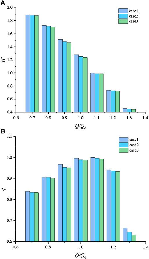
The shaft tubular pump device is widely used in low head pumping stations in plain areas. The N-S equation and the SST k-ω turbulence model are adopted. Then, the investigation on the influence of the shaft transition form on the inflow pattern and hydrodynamic characteristics of the pre-shaft tubular pump device is carried out. By designing three transition forms of shafts, different inflow patterns are provided for the tubular pump device. The characteristic parameters of the shafts and external and internal flow characteristics of the pumping device under different inflow patterns are compared and analyzed. Finally, the optimal transition form is selected for model tests, and unsteady pressure pulsation characteristics are studied. The results show that the flow pattern in the inlet passage of each case is relatively uniform and smooth, and the range of the high-efficiency zone of the pump device is roughly within 0.9Qd–1.2Qd. The energy loss and the weighted average angle on the outlet of each case are similar. The axial velocity distribution uniformity on the impeller inlet of case 1 is better than that of the other cases. The numerical simulation results are consistent with the experimental results, and the numerical simulation method is reliable. Under the design condition, the pressure pulsation amplitude at the impeller inlet is the largest. It gradually increases from the hub to the shroud. The main frequency of pressure pulsation is the blade frequency. The pressure pulsation amplitude at the impeller outlet decreases from the hub to the shroud. The main frequency is not constant due to the rotor–stator interaction between the impeller and the guide vane. The outcome will be beneficial to the design and optimization of the shaft tubular pump device, which is helpful for broadening the corresponding theory and applying it to the actual project.
1 Introduction
Shaft tubular pump devices are widely used in extra-low head pumping stations (0–2 m) with low head and large discharge (Liu, 2015; Kan, 2021). The motor operates in the shaft for the shaft tubular pump device, which has a simple structure, small flat size, straight inlet and outlet passages, convenient maintenance, and low construction cost (Jin et al., 2021). According to the location of the shaft, the shaft tubular pump device can be divided into the pre-shaft type and the post-shaft type. The overall flow pattern and hydraulic performance of the pre-shaft tubular pump device are better than those of the post-shaft tubular pump device. Therefore, the pre-shaft tubular pump device is more commonly applied in the pumping station (Chen et al., 2014).
With the development of CFD (computational fluid dynamics), numerical simulation has become a mature research tool and has been widely used in hydraulic engineering. On the one hand, some researchers have paid attention to the shaft tubular pump device by using the CFD method in recent years (Gonza´lez et al., 2002; Landvogt et al., 2014; Lucius and Brenner, 2011; Kan et al., 2021a; Kan et al., 2021b; Kan et al., 2020; Ansar et al., 2002). Liu et al. (2010) studied and analyzed the flow pattern of the pre-shaft and post-shaft tubular pumps. The results show that the guide vane and the shaft are the key factors affecting the flow pattern in the inlet passage and the efficiency of the device. Xu et al. (2011), (2012) conducted a comprehensive study on the shaft tubular pump device and pointed out the excellent hydraulic performance of the shaft tubular pump device. Lu and Zhang (2012) conducted a model test study on the shaft tubular pump device of an extra-low head pumping station and analyzed its hydraulic performance at different blade angles. Yang et al. (2014a) and (2014b) studied the evolution of the shaft profile and its effect on the internal flow characteristics of the tubular pump system, and the one-dimensional hydraulic design method is used to optimize the inlet passage. Shi et al. (2016) utilized the CFD method combined with a model test to finish the design optimization of the bidirectional shaft tubular pump device. The results showed that the inside and outside lines of the bifurcation segment type of the inlet passage had a large impact on the hydraulic loss of the inlet passage and directly affected the hydraulic loss of the following part after the bifurcation segment of the inlet passage. Meng et al. (2017) investigated the guide vane position affecting the hydraulic performance and flow pattern of the bidirectional tubular pump device. In addition, Xie et al. (2015), Zhou et al. (2021), and Qian et al. (2022) also optimized the shaft tubular pump device. The results showed that the optimization of the shaft tail profile is more beneficial to reducing hydraulic loss than the optimization of the shaft head profile and length, while optimizing the bifurcation segment profile of the shaft can significantly improve the hydraulic performance of the pump device. On the other hand, lots of previous research work about the pressure pulsation in hydraulic machinery had also been carried out. Zhu et al. (2010) pointed out that pressure pulsation has an important effect on the stable operation of the pump device. Wang et al. (2007) used a large eddy simulation method to conduct a more comprehensive and in-depth study and analysis of the pressure pulsation characteristics in the axial flow pump. The main frequency of the pressure pulsation in the axial flow pump is the blade frequency, and the pulsation at the outlet of the guide vane is dominated by low frequency. Dai et al. (2013) analyzed the effect of the turbulent flow model on pressure pulsation and pointed out that the SST k-ω model is suitable for studying the pressure pulsation of circulating pumps. Zhen et al. (2010) studied the pressure pulsation characteristics of the axial flow pump under different blade angles of the impeller and heads by using the model test method. Zhang et al. (2014) measured the pressure pulsation of the axial flow pump under different conditions. The experimental results revealed the pressure pulsation law at different locations inside the axial flow pump. Shi et al. (2014) tested the pressure pulsation of the key points at different speeds for the axial-flow pump. Shen et al. (2018) utilized the computational fluid dynamics method to study the hydrodynamic characteristics of the axial flow pump with different tip clearance distances. Wei et al. (2019) studied the propagation of pressure pulsation in a two-stage double suction centrifugal pump using an unsteady method. Al‐Obaidi (2020) studied the hydrodynamic characteristics of axial flow pumps with different impeller blade numbers. Ji et al. (2022) compared the hydraulic performance and pressure pulsation characteristics of the pre-shaft tubular pump and the post-shaft tubular pump by applying the numerical simulation and model test method. Shi et al. (2021) investigated the pressure pulsation characteristics between a full tubular pump and an axial flow pump based on the CFD method.
In this study, a pre-shaft tubular pumping station is used as the research object. By using the CFD method, the inflow pattern of the tubular pump with different shaft transition types and its influence on its hydraulic performance are analyzed. Then, the optimal shaft transition form is confirmed to promote the model experiment and unsteady pressure pulsation characteristics in the following. The results will benefit the optimization of the inlet passage design for the shaft tubular pump.
2 Numerical Simulation
2.1 Governing Equations
The flow in the shaft tubular pump device follows the mass conservation equation and the momentum conservation equation. In this study, the Reynolds time-averaged N-S equation is selected to describe the flow in the shaft tubular pump device, and its governing equation (Kan et al., 2020) is as follows:
The continuity equation is as follows:
The momentum equation is expressed as follows:
where
The shear–stress transport (SST) k-ω (Zhao et al., 2021) turbulence model can modify the turbulent viscosity equation. Thus, the shear stress on the wall and the flow in the near-wall region are better transferred and predicted. Moreover, the over-prediction of the turbulent viscosity can be avoided. Therefore, the SST k-ω turbulence model is chosen to close the governing equations, where the turbulent kinetic energy k equation is as follows:
The turbulent dissipation rate ω equation is given by the following:
where Uj is the vector velocity, m/s. μt is the turbulent viscosity, m2/s. Pk is the turbulent generation rate. F1 is the mixing function. β′ is the empirical coefficient, usually taken as 0.09. α, β, and σ are correlation constants.
2.2 Computational Domain
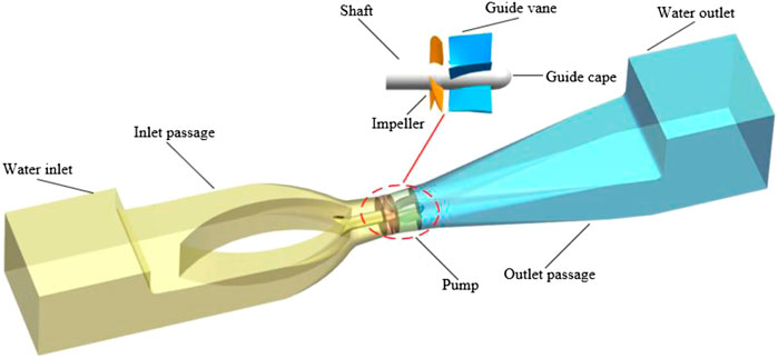
To ensure the incoming and outgoing flow patterns of the inlet and outlet passages, the extension parts named as the water inlet and water outlet are provided before the inlet passage and after the outlet passage, respectively. In other words, the computational domain includes the water inlet, inlet passage, impeller, guide vane, outlet passage, and water outlet, as shown in Figure 1. Its main design parameters are listed in Table 1 below.
2.3 Mesh Generation
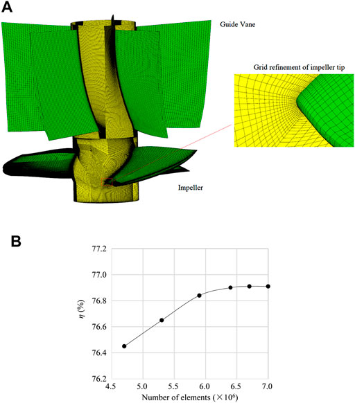
Based on the ANSYS ICEM platform, the pre-shaft tubular pump is divided into blocks, and the structured meshes are generated, as shown in Figure 2A. The inlet passage is spatially discretized with a more adaptive unstructured mesh. To obtain the reliable mesh, the grid-independence analysis is performed. The efficiency is selected as the characteristic parameter. Figure 2B shows the efficiency growth trend of six different meshes under the design condition. When the number of grids exceeds 6.74 million, the error of the efficiency is less than 0.04%, so the number of meshes is confirmed as 6.74 million.
2.4 Boundary Condition
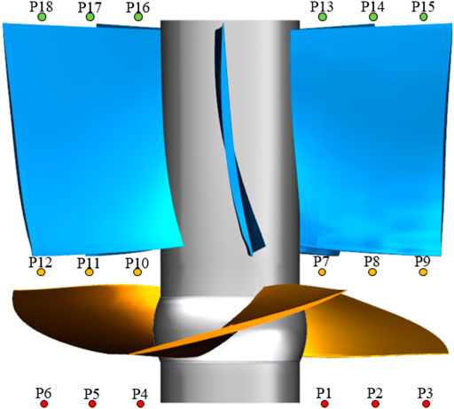
For steady simulation, the inlet of the water inlet is set as the mass flow. The outlet of the water outlet is set as the pressure. The impeller is set as the rotational domain with a speed of −981 rev/min. The “Stage” model is applied for the interfaces between the rotating domain and the non-rotating domain, such as the “inlet passage outlet—impeller inlet” interface and the “impeller outlet—guide vane inlet” interface. All other interfaces are static interfaces. No slip boundary is adopted for the wall, and the near-wall region is treated as a standard wall function. The convergence accuracy is set to 1.0 × 10⁻⁴. Under unsteady simulation, the time step is set to 1.02 × 10⁻⁴ s, the impeller rotates 6° per time step, and the total calculation time is 0.489 s. The monitoring probes are shown in Figure 3. Two groups of monitoring probes are arranged from the hub to the shroud on the outlet of the impeller, which are P1–P3 and P4–P6. Another two groups of monitoring probes are arranged along the radial direction on the inlet of the impeller, which are P7–P9 and P10–P12. In addition, two groups of monitoring probes are arranged from the hub to the shroud on the outlet of the guide vane, which are P13–P15 and P16–P18.
2.5 Model Test
Figure 4A shows the high-precision hydraulic cycle test system. The system has a comprehensive error of ±0.39%. The random error of this experiment is ±0.1321%. Meanwhile, based on the pump head and efficiency of the best efficiency point, the head and efficiency of the other conditions are normalized. Figure 4B shows the numerical simulation results and the experiment results. The external characteristic curves obtained from the numerical simulation and the experiment are basically consistent. The errors of the efficiency and the head under the design condition are not more than 5%. It shows that the numerical simulation method is reliable.
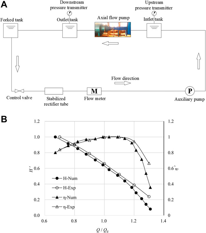
FIGURE 4. (A) Schematic diagram of the test system. (B) Experimental and numerical simulation results.
3 Research Cases
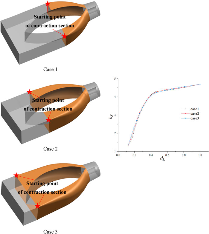
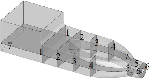
In order to obtain the influence on the hydrodynamic characteristics of the shaft tubular pump device under different inflow patterns, three different transition forms of the shaft are designed. As shown in Figure 5, the sections are sliced and numbered from the outlet to the inlet of the inlet passage, according to the location of the beginning of the contraction section. The bS is the relative area, which is obtained by bi/S, where bi is the area of the ith section, and S is the impeller inlet area. dL is the relative spacing, which is calculated by di/L, where di is the distance of the inlet section of the inlet passage of the ith section, and L is the total length of the inlet passage.
4 Result Analysis
4.1 External Characteristics
The head and efficiency reflect the external characteristic performance of the pump unit. Based on the head and efficiency of the best efficiency point of case 1, the head and efficiency of the other conditions are normalized. The dimensionless head and efficiency of each case are shown in Figure 6A,B.
4.2 Analysis Sections and Parameters
4.2.1 Analysis Sections
To capture the energy characteristics and flow features of the inlet passage in detail, seven characteristic sections are sliced along the flow direction, which is noted as n-n sections (n takes 1–7). As shown in Figure 7, the seven characteristic sections are the inlet section of the inlet passage, the starting transition section of each case, the outlet section of the inlet passage, and the center section of the inlet passage, which are intercepted sequentially.
4.2.2 Analysis Parameters
An evaluation index should be introduced to quantitatively analyze the hydraulic performance of the inlet passage of each case. Therefore, energy loss ratio ζ, axial velocity distribution uniformity Vu, and velocity-weighted average angle θ are defined. The energy loss ratio ζ represents the ratio of the energy loss ΔCi of each adjacent section at different conditions to the total energy loss ΔCt of the intake passage of case 1 under the optimal condition. Axial velocity distribution uniformity Vu indicates the uniformity of axial velocity distribution on the outlet section of the inlet passage. The velocity-weighted average angle θ indicates the angle between the velocity at the outlet of the inlet passage and the outlet cross section. Generally speaking, when the axial velocity distribution uniformity Vu is closer to 100%, the velocity distribution is more uniform. When the velocity-weighted average angle θ is closer to 90°, the flow goes smoothly. Similarly, the smaller the inlet passage energy loss ratio ζ, the higher the efficiency is.
where Hi denotes the elevation of the section, m. Pi denotes the total pressure of the section, Pa. vi denotes the average velocity of the section, m.
where
4.3 Internal Flow Characteristics
Figure 8 shows the static pressure distribution and streamlines on section 7-7 and the velocity contours on section 5-5 with different transition forms under various conditions. As shown in Figure 10, the overall flow patterns in the inlet passage for all three cases are smooth, and there is no separation flow. At the head of the shaft, the flow is evenly divided into two streams. The velocity on both sides of the shaft increases, and the pressure decreases when the sections tend to contract. The streamline and pressure distribution are symmetrical on both sides of the shaft. At the end of the shaft, the flow merges into one stream smoothly. There is a small low pressure area on both sides of the end in the contraction segment of the shaft. The low pressure area of cases 2 and 3 is approximately the same, which are slightly larger than that of case 1. Thus, section 5-5 is sliced, and there is a symmetrically distributed high velocity area which is corresponding to the low pressure area. The velocity at the outside of the shaft is larger than at the inside, and such a trend appears more obvious when the flow rate enlarges.
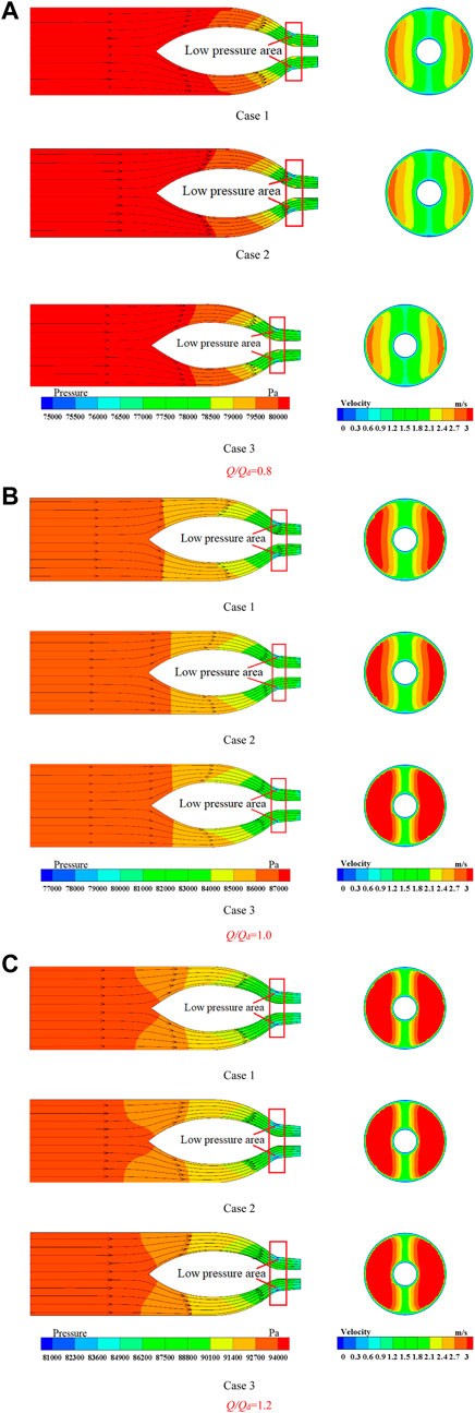
FIGURE 8. Streamlines and the pressure distribution on the center section (left) and the velocity distribution on section 5-5 (right) of different cases under each condition. (A) Q/Qd = 0.8 (B) Q/Qd = 1.0 (C) Q/Qd = 1.2.
The inlet passage is mainly installed to provide a uniform flow pattern for the impeller. Therefore, it should ensure and give priority to the uniformity of the velocity on the outlet of the inlet passage. As shown in Figure 9, the velocity contours on the outlet of the inlet passage of each case under different conditions are given. As shown in Figure 9, the velocity on the outlet of each case is symmetrically distributed bilaterally and vertically under different conditions. The low velocity near the wall is observed. The velocity growth rate near the shaft is significantly greater than that which is far away from the shaft on the outlet.
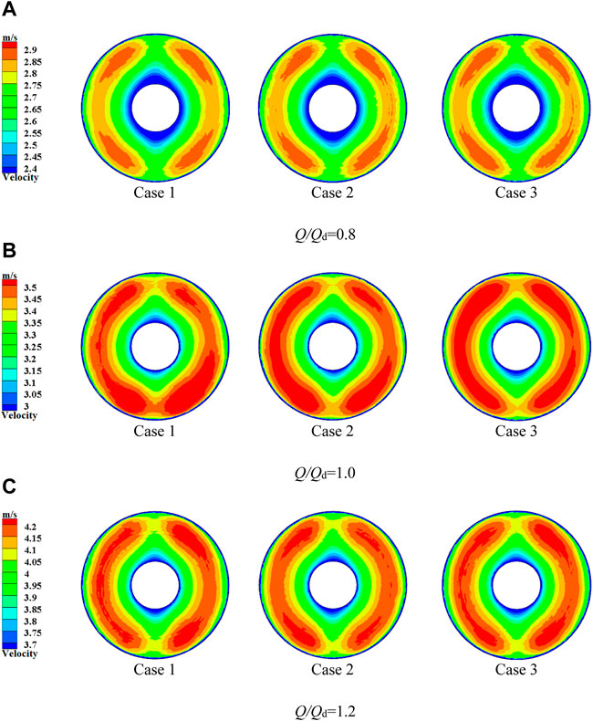
FIGURE 9. Velocity contours on the outlet of the inlet passage. (A) Q/Qd = 0.8 (B) Q/Qd = 1.0 (C) Q/Qd = 1.2.
Under the same condition, the velocity distribution on the outlet of each case shares the same trend. The velocity magnitude is basically similar. The symmetrical contraction on the left and right is much larger than that on the top and bottom. The mainstream is concentrated on the left and right near the outside, and the velocity on the top and bottom near the inside tends to be small. Moreover, the velocity distribution on the outlet is positively correlated with the flow rate. The maximum velocity under the condition of 1.0Qd is about 1.20 times the maximum velocity under the condition of 0.8Qd. However, the maximum velocity under the condition of 1.2Qd is also about 1.20 times the maximum velocity under the condition of 1.0Qd.
4.4 Energy Characteristics
Figure 10 shows the energy characteristics’ trend of each section for each case under different conditions. The horizontal coordinate is the relative distance of each section from the outlet of the inlet passage, which is defined as x/l. The vertical coordinate is the energy loss ratio ζ of the section. For the inlet passage, the energy loss in the inlet passage is hydraulic loss, and there is no leakage loss. As shown in Figure 10, the energy from the inlet to the outlet in the inlet passage decreases with the increasing flow rates. In other words, the hydraulic losses keep increasing. The largest energy loss of each case happens in the shaft tail, which is from section 4-4 to section 6-6 under different conditions. Another major energy loss is located from section 3-3 to section 4-4. The energy loss originates from the severe transition of the shaft. The energy loss of case 1 is significantly smaller than that of the other two cases.
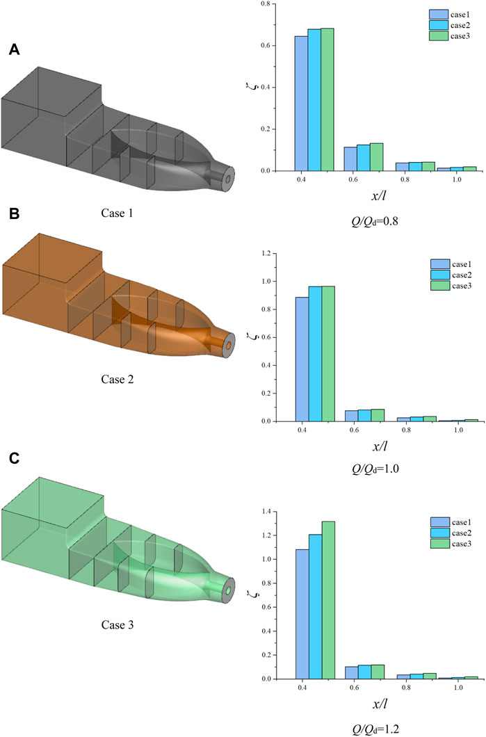
FIGURE 10. Energy characteristics in the inlet passage for each case. (A) Q/Qd = 0.8 (B) Q/Qd = 1.0 (C) Q/Qd = 1.2.
4.5 Velocity Uniformity Characteristics
Figure 11 shows the axial velocity distribution uniformity Vu and the velocity-weighted average angle θ on the outlet of the inlet passage for each case under different conditions. It can be seen that Vu and θ increase rapidly in the flow rate range of 0.8Qd to 1.1Qd, and then, the increment is small. The Vu of case 1 is the highest. The axial velocity distribution uniformity is the best under the condition of 1.2Qd, whose value is 96.47%. The Vu and θ of case 3 are the worst, and its axial velocity distribution uniformity is the worst under the condition of 0.8Qd, whose value is 93.06%. Under the same flow rate condition, the axial velocity distribution uniformity on the outlet of the inlet passage for case 1 and case 2 is nearly the same, which is higher than that of case 3. The velocity-weighted average angle on the outlet of the inlet passage for case 1 is the largest, reaching 88.86°.
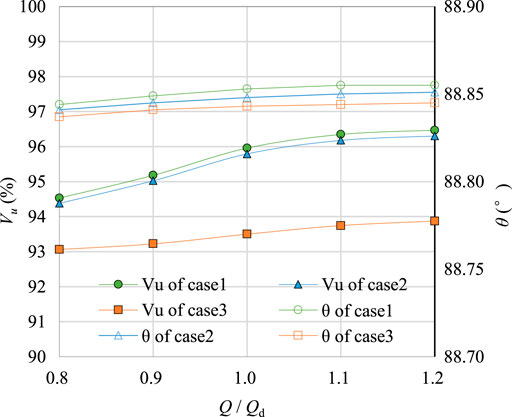
FIGURE 11. Axial velocity distribution uniformity Vu and the velocity-weighted average angle θ on the outlet of the inlet passage for each case.
4.6 Pressure Pulsation Characteristics
The complex flow in the axial flow pump can lead to rapid pressure pulsation, which causes vibration and noise that reduces the efficiency and the life cycle of the pump. The flow is not stable in the early periods; therefore, the data on the last four periods are selected to analyze the pressure pulsation.
To establish the relationship between the pressure pulsation and the flow rate, the pressure pulsation of monitoring points P1-P3, P7-P9, and P13-P15 under the flow rate conditions of 0.8Qd, 1.0Qd, and 1.2Qd is compared.
The pressure pulsation coefficient Cp and the multiplier of the shaft frequency fn are introduced and calculated as follows :
where F is the frequency by utilizing fast Fourier transform, Hz. p is the pressure at the monitoring point, Pa.
Figure 12 shows the time domain chart (subfigures on the left) and frequency domain chart (subfigures on the right) of the pressure pulsation on the impeller inlet at monitoring points P1-P3 under different conditions. In the time domain chart of Figure 12, it can be seen that the pressure pulsation under each condition is sinusoidally distributed with obvious periodic fluctuations. When the rotator runs per round, three peaks and troughs appear. The number of peaks and troughs is consistent with the blade number. The farther the monitoring point is from the hub, the larger the pressure pulsation amplitude is. The pressure pulsation amplitude of P3 is about 1.83 times that of P1 under the conditions of 0.8Qd, 1.0Qd, and 1.2Qd. The pressure pulsation of the impeller inlet is obviously periodic under each condition.
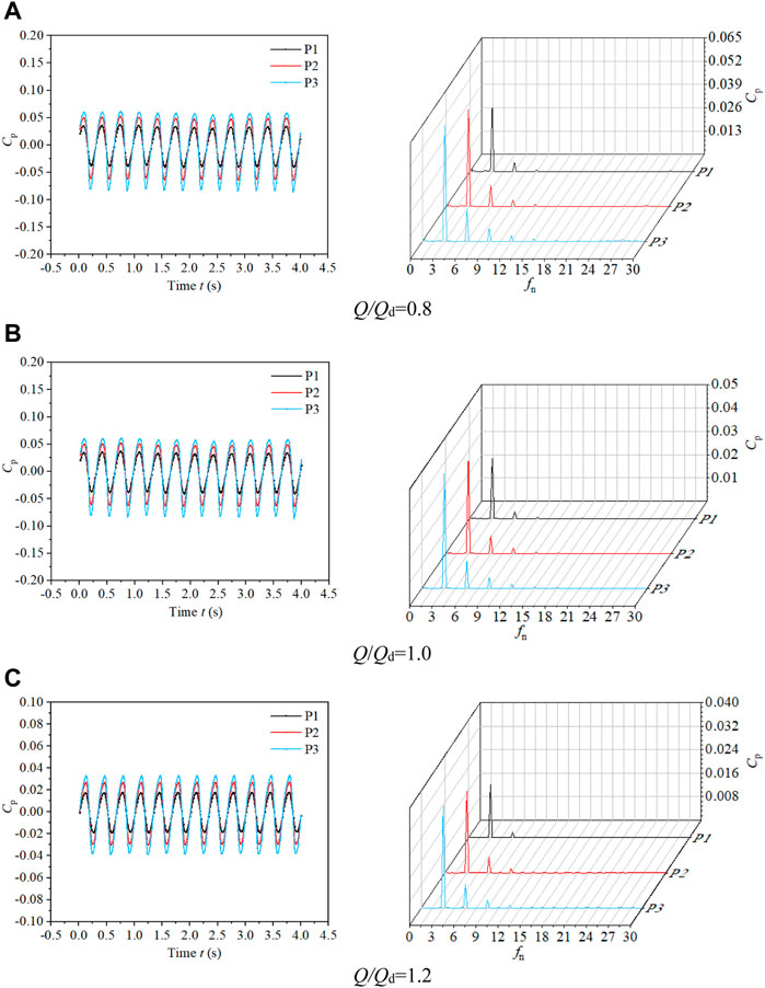
FIGURE 12. Time domain chart and frequency domain chart of pressure pulsation on the impeller inlet at monitoring points P1-P3 under different conditions. (A) Q/Qd = 0.8 (B) Q/Qd = 1.0 (C) Q/Qd = 1.2.
In the frequency domain chart of Figure 12, the amplitude of monitoring points P1, P2, and P3 increases gradually from the hub to the shroud along the radial direction at the impeller inlet under each condition. The pressure pulsation amplitude of P2 under the condition of 0.8Qd is 1.36 times than that under the condition of 1.0Qd and 1.94 times than that under the condition of 1.2Qd, respectively. Meanwhile, the main frequency of each monitoring point is 3 times the shaft frequency, and the secondary frequency is 6 times the shaft frequency. Therefore, the pressure pulsation at the impeller inlet is greatly influenced by the blade number.
Figure 13 shows the time domain chart (subfigures on the left) and frequency domain chart (subfigures on the right) of the pressure pulsation on the impeller outlet at monitoring points P7-P9 under different conditions. In the time domain chart of Figure 13, it is shown that the general trend of pressure pulsation of each condition is consistent. There are three peaks and troughs in a period for P7 and P8. However, there are five peaks and troughs for P9. The result shows that the pressure pulsation at the impeller outlet is still mainly influenced by the blade number of the impeller. For the monitoring point P9, the guide vane number dominates the growth low of the pressure pulsation on it. The reason is its location, which is close to the shroud of the impeller outlet and the guide vane.
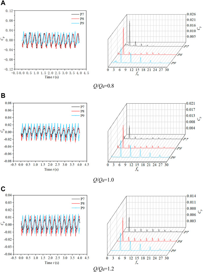
FIGURE 13. Time domain chart and frequency domain chart of pressure pulsation on the impeller outlet at monitoring points P7-P9 under different conditions. (A) Q/Qd = 0.8 (B) Q/Qd = 1.0 ((C) Q/Qd = 1.2.
In the frequency domain chart of Figure 13, the main frequencies of P7 and P8 at the impeller outlet are 3 times the shaft frequency under each condition. The main frequency of P9 is 5 times the shaft frequency. The pressure pulsation amplitude grows higher from the shroud to the hub. Due to the rotor–stator interaction between the impeller and the guide vane existing in the pump, the frequency spectrum is varied. Considering that the strength of the circulation caused by the pre-rotation of the impeller exceeds the circulation recovery caused by the guide vane, the absolute value of the pressure pulsation on the inlet of the impeller is larger than that on the outlet of the impeller for each case.
Figure 14 shows the time domain chart (subfigures on the left) and frequency domain chart (subfigures on the right) of the pressure pulsation on the guide vane outlet at monitoring points P13-P15 under different conditions. In the time domain chart of Figure 14, there is no obvious regular pattern and periodicity of the pressure pulsation for each condition, and random pulsation is observed. Under the conditions of 0.8Qd and 1.0Qd, the wave of the pressure pulsation is relatively disordered. Under the condition of 1.2Qd, there are three peaks and troughs in a period. It shows that the pressure pulsation at the outlet of the guide vane is still influenced by the blade number of the impeller.
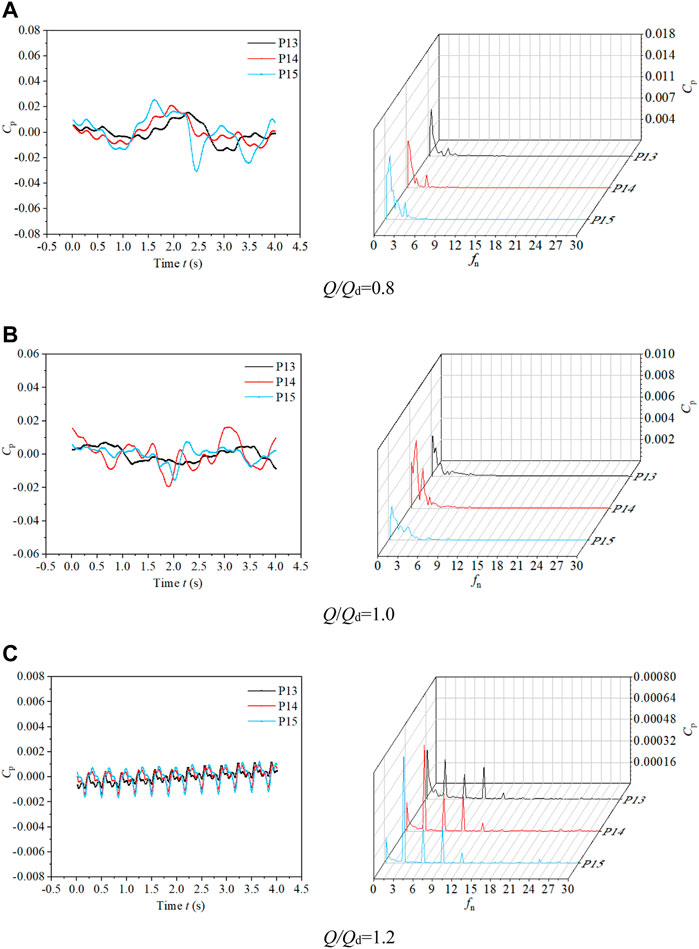
FIGURE 14. Time domain chart and frequency domain chart of pressure pulsation on the guide vane outlet at monitoring points P13-P15 under different conditions. (A) Q/Qd = 0.8 (B) Q/Qd = 1.0 (C) Q/Qd = 1.2.
In the frequency domain chart of Figure 14, it is found that the frequency spectrum of the pressure pulsation at each monitoring point at the outlet of the guide vane under each condition is more complex due to the hydraulic conductivity and energy recovery of the guide vane, which is obviously different from the pressure pulsation characteristics of the impeller inlet and outlet. Under the conditions of 0.8Qd and 1.0Qd, the pressure pulsation in the low frequency band is more complex, and the major frequency at each monitoring point is not obvious, and the amplitude is similar. Under the condition of 1.2Qd, the major frequency of the pressure pulsation at each monitoring point is the shaft frequency. But there are multiple secondary frequencies near it, which are multiples of the shaft frequency of the impeller.
5 Conclusion
In this study, the investigation on the influence of the shaft transition form on the inflow pattern and hydrodynamic characteristics of the pre-shaft tubular pump device is carried out by using the CFD method. The pump device with the optimal transition form of the shaft is experimented upon, and unsteady pressure pulsation characteristics are studied. The conclusions are as follows:
1) The numerical simulation results are verified with model tests. The numerical simulation prediction results and experimental results are compared under different flow rate conditions. The errors are less than 5%, and the hydraulic performance curves match well. The numerical method is reliable, and the result is correct.
2) The hydraulic performance of case 1 is better than that of case 2 and case 3. The flow rate of the high-efficiency region is roughly in the range of 0.9Qd–1.2Qd.
3) The flow in the inlet passage of three cases is smooth, and no obvious separation flow is observed. The velocity contours on the outlet of the shaft are symmetrically distributed bilaterally and vertically, providing the outstanding flow pattern for the impeller.
4) The transition form of the shaft has a limited effect on the energy characteristics and the weighted average angle of the inlet passage. The smoother the inlet passage transits, the lower the energy loss is. The axial velocity uniformity on the outlet of the inlet passage for case 1 is better than that of the other cases.
5) The periodic pressure pulsation at the impeller inlet is obvious, and the amplitude is the largest compared with the impeller outlet and the guide vane outlet. The pressure pulsation increases from the hub to the shroud. However, the pressure pulsation at the guide vane outlet is aperiodic, and the amplitude is the smallest. The pressure pulsation near the hub is larger than that near the shroud.
6) The pressure pulsation at the impeller inlet is mainly related to the blade number of the impeller. Thus, the main frequency at the impeller inlet is the blade frequency. The main frequency near the hub at the impeller outlet also follows the regular pattern as mentioned previously. On the contrary, the main frequency near the shroud at the impeller outlet is related to the guide vane, and its value is not the blade frequency. In addition, the pressure pulsation at the guide vane outlet is also affected by the impeller under large flow rate conditions.
Data Availability Statement
The raw data supporting the conclusion of this article will be made available by the authors, without undue reservation.
Author Contributions
LC, data curation; WQ, formal analysis; JL and CL, methodology; CL and KD, writing—original draft; CL, KD, and WQ, writing—review and editing; XH, supervision.
Funding
This research was funded by the Jiangsu Province Science Foundation for Youths (Grant no. BK20170507), the Natural Science Foundation of the Jiangsu Higher Education Institutions (Grant no. 17KJD580003), the Jiangsu Planned Projects for Postdoctoral Research Funds (Grant no. 1701189B), the Open Research Subject of Key Laboratory of Fluid and Power Machinery (Xihua University), the Ministry of Education (Grant nos. szjj2019-018), the National Natural Science Foundation of China (Grant Nos. 51779214 and 51909231), the Open Research Subject of Key Laboratory of Fluid and Power Machinery (Xihua University), the Ministry of Education (Grant number LTDL2021-009), and the Priority Academic Program Development of Jiangsu Higher Education Institutions (PAPD).
Conflict of Interest
WQ was employed by Huaian Water Conservancy Survey Design and Research Institute Co., Ltd.
The remaining authors declare that the research was conducted in the absence of any commercial or financial relationships that could be construed as a potential conflict of interest.
Publisher’s Note
All claims expressed in this article are solely those of the authors and do not necessarily represent those of their affiliated organizations, or those of the publisher, the editors, and the reviewers. Any product that may be evaluated in this article, or claim that may be made by its manufacturer, is not guaranteed or endorsed by the publisher.
References
Al‐Obaidi, A. R. (2020). Investigation of the Influence of Various Numbers of Impeller Blades on Internal Flow Field Analysis and the Pressure Pulsation of an Axial Pump Based on Transient Flow Behavior. Heat. Transf. 49 (4), 2000–2024. doi:10.1002/htj.21704
Ansar, M., Nakato, T., and Constantinescu, G. (2002). Numerical Simulations of Inviscid Three-Dimensional Flows at Single- and Dual-Pump Intakes. J. Hydraulic Res. 40 (4), 461–470. doi:10.1080/00221680209499888
Chen, S., Yan, H., Zhou, Z., He, Z., and Wang, L. (2014). Three-dimensional Turbulent Numerical Simulation and Model Test of Fro Shaft Tubular Inlet Conduit of the Pumping Station. Trans. Chin. Soc. Agric. Eng. 30 (02), 63–71. doi:10.3969/j.issn.1002-6819.2014.02.009
Dai, C., Kong, F.-y., and Dong, L. (2013). Pressure Fluctuation and its Influencing Factors in Circulating Water Pump. J. Cent. South Univ. 20 (1), 149–155. doi:10.1007/s11771-013-1470-6
Gonza´lez, J., Ferna´ndez, J. n., Blanco, E., and Santolaria, C. (2002). Numerical Simulation of the Dynamic Effects Due to Impeller-Volute Interaction in a Centrifugal Pump. J. Fluids Eng. 124 (2), 348–355. doi:10.1115/1.1457452
Ji, D., Lu, W., Lu, L., Xu, L., Liu, J., Shi, W., et al. (2022). Study on the Comparison of the Hydraulic Performance and Pressure Pulsation Characteristics of a Shaft Front-Positioned and a Shaft Rear-Positioned Tubular Pump Devices. Jmse 10, 8. doi:10.3390/jmse10010008
Jin, K., Chen, Y., Tang, F., Shi, L., Liu, H., and Zhang, W. (2021). Influence of Shaft Location on Hydraulic Characteristics of Bidirectional Tubular Pump Systems. J. Hydroelectr. Eng. 40 (09), 67–77. doi:10.11660/slfdxb.20210907
Kan, K. (2021). Hydrodynamic and Structural Stability Analysis for Shaft Tubular Pump Unit. IOP Conf. Ser. Earth Environ. Sci. 647 (1), 012038. doi:10.1088/1755-1315/647/1/012038
Kan, K., Chen, H., Zheng, Y., Zhou, D., Binama, M., and Dai, J. (2021). Transient Characteristics during Power-Off Process in a Shaft Extension Tubular Pump by Using a Suitable Numerical Model. Renew. Energy 164, 109–121. doi:10.1016/j.renene.2020.09.001
Kan, K., Yang, Z., Lyu, P., Zheng, Y., and Shen, L. (2021). Numerical Study of Turbulent Flow Past a Rotating Axial-Flow Pump Based on a Level-Set Immersed Boundary Method. Renew. Energy 168, 960–971. doi:10.1016/j.renene.2020.12.103
Kan, K., Zheng, Y., Chen, H., Zhou, D., Dai, J., Binama, M., et al. (2020). Numerical Simulation of Transient Flow in a Shaft Extension Tubular Pump Unit during Runaway Process Caused by Power Failure. Renew. Energy 154, 1153–1164. doi:10.1016/j.renene.2020.03.057
Landvogt, B., Osiecki, L., Patrosz, P., Zawistowski, T., and Zylinski, B. (2014). Numerical Simulation of Fluid-Structure Interaction in the Design Process for a New Axial Hydraulic Pump. Prog. Comput. Fluid Dyn. 14 (1), 31–37. doi:10.1504/PCFD.2014.059198
Liu, C. (2015). Researches and Developments of Axial-Flow Pump System. Trans. Chin. Soc. Agric. Mach. 46 (06), 49–59. doi:10.6041/j.issn.1000-1298.2015.06.008
Liu, J., Zhen, Y., Zhou, D., Mao, Y., and Zhang, L. (2010). Analysis of Basic Flow Pattern in Shaft Front-Positioned and Shaft Rea Positioned Tubular Pump Systems. Trans. Chin. Soc. Agric. Mach. 41 (S1), 32–38. doi:10.3969/j.issn.1000-1298
Lu, W., and Zhang, X. (2012). Research on the Model Test of Hydraulic Characteristics for Super-low Hea Shaft-Well Tubular Pump Unit. J. Irrigation Drainage 31 (06), 103–106+125. doi:10.13522/j.cnki.ggps.2012.06.009
Lucius, A., and Brenner, G. (2011). Numerical Simulation and Evaluation of Velocity Fluctuations During Rotating Stall of a Centrifugal Pump. J. Fluids Eng. 133 (8), 081102. doi:10.1115/1.4004636
Meng, F., Pei, J., Li, Y., Yuan, S., and Chen, J. (2017). Effect of Guide Vane Position on the Hydraulic Performance of Two-Direction Tubular Pump Device. Trans. Chin. Soc. Agric. Mach. 48 (02), 135–140. doi:10.6041/j.issn.1000-1298.2017.02.018
Qian, Z., Zhou, X., Jiao, H., Xia, Z., and Chen, S. (2022). Research on the Passage and Front Guide Vane of Shaft Tubular Pump Unit Based on CFD. J. China Rural Water Hydropower (05), 101–106+112.
Shen, S., Qian, Z., Ji, B., and Agarwal, R. K. (2018). Numerical Investigation of Tip Flow Dynamics and Main Flow Characteristics with Varying Tip Clearance Widths for an Axial-Flow Pump. Proc. Institution Mech. Eng. Part A J. Power Energy 233, 476–488. doi:10.1177/0957650918812541
Shi, D., Yao, J., Zhang, S., Wu, Q., and Wang, Y. (2014). Test Comparative Study on the Impact of Different Revolving Speeds on Pressure Fluctuation in Axial Flow Pumps. Trans. Chin. Soc. Agric. Mach. 45 (03), 66–71. doi:10.6041/j.issn.1000-1298.2014.03.012
Shi, L., Liu, X., Tang, F., Yao, Y., Xie, S., and Zhang, W. (2016). Design Optimization and Experimental Analysis of Bidirectional Shaft Tubular Pump Device. Trans. Chin. Soc. Agric. Mach. 47 (12), 85–91. doi:10.6041/j.issn.1000-1298.2016.12.012
Shi, L., Yuan, Y., Jiao, H., Tang, F., Cheng, L., Yang, F., et al. (2021). Numerical Investigation and Experiment on Pressure Pulsation Characteristics in a Full Tubular Pump. Renew. Energy 163, 987–1000. doi:10.1016/j.renene.2020.09.003
Wang, J., Zhang, L., and Zhang, M. (2007). Analysis of Pressure Fluctuation of Non-constant Flow in Axial-Flow Pump. J. Hydraulic Eng. 38 (08), 1003–1009. doi:10.3321/j.issn:0559-9350.2007.08.019
Wei, Z., Yang, W., and Xiao, R. (2019). Pressure Fluctuation and Flow Characteristics in a Two-Stage Double-Suction Centrifugal Pump. Symmetry 11 (1), 65. doi:10.3390/sym11010065
Xie, R., Wu, Z., He, Y., Tang, F., Xie, C., and Tu, L. (2015). Optimization Research on Passage of Bidirectional Shaft Tubular Pump. Trans. Chin. Soc. Agric. Mach. 46 (10), 68–74. doi:10.6041/j.issn.1000-1298.2015.10.011
Xu, L., Lu, L. G., Chen, W., and Wang, G. (2012). Flow Pattern Analysis on Inlet and Outlet Conduit of Shaft Tubular Pump System of Pizhou Pumping Station in South-To-North Water Diversion Project. Trans. Chin. Soc. Agric. Eng. 28 (06), 50–56. doi:10.3969/j.issn.1002-6819.2012.06.009
Xu, L., Lu, L. G., Chen, W., and Wang, G. (2011). Study on Comparison of Hydraulic Design Cases for Shaft Tubular Pump System. J. Hydroelectr. Eng. 30 (05), 207–215. CNKI:SUN:SFXB.0.2011-05-036.
Yang, F., Liu, C., Tang, F., and Zhou, J. (2014). Shaft Shape Evolution and Analysis of its Effect on the Pumping System Hydraulic Performance. J. Basic Sci. Eng. 22 (01), 129–138. doi:10.3969/j.issn.1005-0930.2014.01.013
Yang, F., Liu, C., Tang, P., Cheng, L., and Lv, D. (2014). Numerical Simulation of 3D Internal Flow and Performance Analysis of the Shaft Tubular Pump System. J. Hydroelectr. Eng. 33 (01), 178–184. CNKI:SUN:SFXB.0.2014-01-028.
Zhang, S., Wang, Y., Shi, D., and Shao, P. (2014). Analysis of Pressure Fluctuation of Non-constant Flow in Axial-Flow Pump. J. Hydraulic Eng. 45 (11), 139–145. doi:10.6041/j.issn.1000-1298.2014.11.022
Zhao, W., Zhang, J., Yu, X., Zhou, D., and Calamak, M. (2021). Multiobjective Optimization of a Tubular Pump to Improve the Applicable Operating Head and Hydraulic Performance. Proc. Institution Mech. Eng. Part C J. Mech. Eng. Sci. 235 (9), 1555–1566. doi:10.1177/0954406220947116
Zhen, Y., Liu, J., Zhou, Q., Mao, T., and Liu, Q. (2010). Pressure Pulsation of Model Test in Large-Size Axial-Flow Pump. J. Drainage Irrigation Mach. Eng. 28 (01), 51–55. JournalArticle/5af5957cc095d718d826de01.
Zhou, C., Zhang, J., Jiao, W., Cheng, L., and Jiang, Y. (2021). Numerical Simulation of the Influence of Shaft on the Performance of Low Heat Tubular Pumping System. J. Drainage Irrigation Mach. Eng. 39 (03), 231–237. doi:10.3969/j.issn.1674-8530.20.0148
Keywords: shaft tubular pump device, shaft transition, hydraulic performance, pressure pulsation, numerical simulation, model test
Citation: Luo C, Du K, Qi W, Cheng L, Huang X and Lu J (2022) Investigation on the Effect of the Shaft Transition Form on the Inflow Pattern and Hydrodynamic Characteristics of the Pre-Shaft Tubular Pump Device. Front. Energy Res. 10:955492. doi: 10.3389/fenrg.2022.955492
Received: 28 May 2022; Accepted: 20 June 2022;
Published: 22 July 2022.
Edited by:
Kan Kan, College of Energy and Electrical Engineering, ChinaReviewed by:
Qiang Gao, University of Minnesota Twin Cities, United StatesShibiao Fang, Shenzhen University, China
Copyright © 2022 Luo, Du, Qi, Cheng, Huang and Lu. This is an open-access article distributed under the terms of the Creative Commons Attribution License (CC BY). The use, distribution or reproduction in other forums is permitted, provided the original author(s) and the copyright owner(s) are credited and that the original publication in this journal is cited, in accordance with accepted academic practice. No use, distribution or reproduction is permitted which does not comply with these terms.
*Correspondence: Can Luo, bHVvY2FuQHl6dS5lZHUuY24=
 Can Luo
 Kang Du1
 Xianbei Huang