- Powerchina Hubei Electric Engineering Co., Ltd, Wuhan, China
The combination of thermal power and hybrid energy storage is an effective way to improve the response ability of automatic generation control (AGC) command in thermal power plants. Notably, the configuration of hybrid energy storage capacity is directly related to improvement of the frequency modulation ability of thermal power plants and the coordination of economic benefits. However, the constant efficiency model adopted in capacity configuration will misjudge the actual operating status of each energy storage unit, resulting in unreasonable capacity allocation. In this context, a fire-storage capacity optimization configuration model considering the dynamic charge–discharge efficiency of hybrid energy storage is established. The model presents the functional relationship between charge and discharge power and the efficiency of different types of energy storage. Simulation proves that the proposed strategy can meet the tracking demand of area control error signal in thermal power plants and reduce the planning and operation cost of energy storage.
1 Introduction
In China, thermal power plants mainly undertake secondary frequency modulation auxiliary services (Jin et al., 2022): adjusting unit output in real time according to automatic generation control (AGC) instructions. In recent years, with the reform of China’s energy structure, the complexity of system AGC instruction characteristics has increased (Sun et al., 2020; Yang et al., 2021; Yang et al., 2022). In this context, the problems of long inherent response delay and low climbing rate of traditional thermal power units (Zhang et al., 2018; Zhang et al., 2021) will increase the tracking error of AGC instructions and make it difficult to ensure the safety of power grid frequency. Energy storage, as a new type of frequency modulation resource, has the characteristics of fast response, accurate control, and two-way output (Meng et al., 2019), which can assist the thermal power plant in instantly tracking power instructions. Therefore, the configuration of a certain capacity energy storage system in a thermal power plant is an effective method to solve the AGC response problem of the whole plant.
There are various types of energy storage inside the hybrid energy storage, which can meet the energy density and power density requirements of frequency modulation instructions. Therefore, compared with single energy storage, hybrid energy storage can greatly improve the AGC response capacity of thermal power plants (Ye et al., 2021; Saxena and Shankar, 2022) and effectively improve the stability and economy of energy storage combination plants. However, the capacity configuration cost of the hybrid energy storage system is contradictory to the improvement of AGC response capability of the whole plant: too much energy storage capacity configuration will lead to increase of energy storage operation planning cost, and too little configuration will lead to failure to compensate for the poor AGC response capability of thermal power units. Therefore, in order to improve the response capacity of AGC of thermal power plants and ensure the economy of energy storage system planning and operation, optimizing the configuration of hybrid energy storage capacity is an important link for energy storage to participate in the large-scale development of AGC response of thermal power plants.
The objectives of the capacity configuration of the AGC frequency modulation hybrid energy storage system for auxiliary thermal power units include the following: 1) improvement in AGC response performance of the whole plant; 2) reduction in the planning and operation cost of the hybrid energy storage system. In order to achieve this goal, it is necessary to allocate the power in the AGC frequency modulation responsibility signal of the energy storage system to different energy storage units so as to give full play to the technical advantages of different energy storage media in the hybrid energy storage system to meet the coordination of economy and regulation of the whole plant.
Yang (2016), Liu et al. (2021), and Meng et al. (2021) set the power distribution strategy of hybrid energy storage based on the decomposition of the Area Control Error (ACE) signal in the frequency domain and carried out capacity optimization on this basis. However, the control cycle of secondary frequency modulation is more than 1 min, and the response time of different types of energy storage devices is within 5 s, so the difference between different response characteristics can be ignored. Therefore, this method is not applicable to the power distribution of hybrid energy storage oriented to AGC of thermal power plants. Wang et al. (2018); Aghajan-Eshkevari et al. (2022) adopt the “priority” allocation method to carry out capacity configuration, such as preferential charging and discharging power allocation method for supercapacitors.
In this way, according to the analysis of the operation mechanism of some auxiliary service markets, the general rule of maximizing profits is obtained, and then the output priority level of each energy storage type is formulated according to the rule, which is more suitable for some specific scenarios. However, this method is subjective and poor in scalability. In the studies by Cheng et al. (2014) and Galatsopoulos et al. (2020), dynamic optimization of the ACE signal allocation ratio is considered in capacity configuration so as to give full play to the frequency modulation potential of different types of energy storage in various scenarios. In the abovementioned study, the charge and discharge efficiency of each type of energy storage is regarded as a constant. In fact, the efficiency of charge and discharge changes dynamically with the distribution of power. Ignoring the dynamic characteristics of charging and discharging efficiency will lead to unreasonable allocation of energy storage capacity and affect the frequency modulation performance and configuration cost of hybrid energy storage. In this regard, the charge–discharge power-efficiency model of the battery energy storage unit was established (Rancilio et al., 2019), but only the dynamic characteristics of the charge–discharge efficiency of a single type of energy storage were considered. Iclodean et al. (2017) discuss the dynamic characteristics of charge and discharge efficiency of compressed air energy storage and electrochemical energy storage, but it is only described by a simple model in the form of a segmented function, which is different from the dynamic model of actual power-charge and discharge efficiency. Furthermore, the previously mentioned pieces of literature did not consider the optimal allocation of capacity.
To sum up, this study adopts a hybrid energy storage system comprising batteries and supercapacitors to assist traditional thermal power plants in providing AGC auxiliary services. Aiming at the capacity configuration problem of the hybrid energy storage system, this study establishes a refinement dynamic model of charging and discharging power efficiency of each type of energy storage unit. Based on this, a fire-storage capacity configuration model considering the dynamic charge–discharge efficiency of hybrid energy storage is constructed to dynamically optimize the proportion of ACE signal allocation so as to obtain the rated energy storage capacity that meets the requirement of instruction tracking and minimizes the cost of energy storage planning and operation. Finally, the superiority and economy of the proposed strategy are verified by simulation.
2 The Dynamic Efficiency Model of Hybrid Energy Storage Charge–Discharge Power
2.1 Dynamic Efficiency Model of Battery
When the battery participates in AGC frequency modulation in a thermal power plant, the incoming power can be changed by adjusting the charge and discharge current of the internal circuit so that it can meet the requirements of auxiliary frequency modulation power. With the dynamic change of charge and discharge current, the battery terminal voltage will also change, so the charge and discharge efficiency determined by the terminal voltage too will change. The mathematical model of dynamic charging and discharging efficiency of the previously mentioned batteries is as follows:
In the formula,
The SOC status of the battery is as follows:
In the formula,
In the formula,
2.2 Dynamic Efficiency Model of a Supercapacitor
In this study, the current loop of the supercapacitor adopts a constant power control mode, and the series structure of ideal capacitance and equivalent series internal resistance is used to simulate the internal circuit of the supercapacitor (Naseri et al., 2021). Unlike batteries, the charging and discharging efficiency of supercapacitors is related only to power.
In the formula,
The SOC of the supercapacitor is as follows:
In the formula,
In the formula,
2.3 Importance Analysis of the Dynamic Efficiency Model of the Energy Storage Unit
In order to analyze the importance of dynamic efficiency of the energy storage unit to capacity allocation, the electric quantity fluctuation range ΔEi,t is introduced as follows:
In the formula,
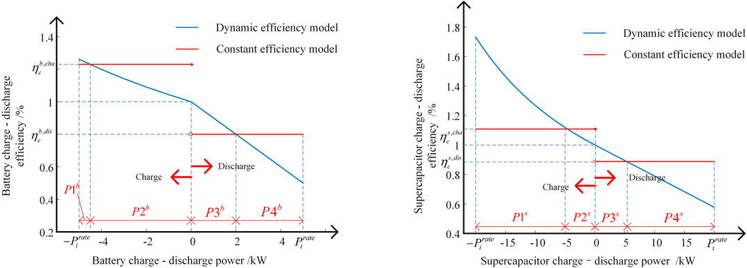
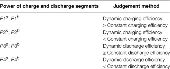
According to Figure 1, different from the constant state of charge and discharge efficiency in the configuration of energy storage capacity at that time, the actual charge and discharge power of the supercapacitor and battery changes dynamically with the power and is inversely proportional to the charge and discharge power. According to the numerical comparison between constant charge and discharge efficiency and dynamic charge and discharge efficiency, the charge and discharge power of each energy storage unit is segmented according to Table 1.
3 Hybrid Energy Storage Capacity Allocation Policy
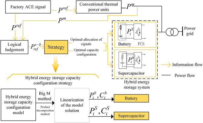
After the hybrid energy storage system is configured in the thermal power plant, the AGC-responsive hybrid energy storage capacity configuration strategy is shown in Figure 2. In Figure 2, Pref depicts the ACE signal transmitted by the AGC dispatching center to a thermal power plant, Pm is the real-time output of the conventional units in the thermal power plant jointly responding to the ACE signal, and the ACE signal tracking error
The key to the hybrid energy storage capacity configuration strategy is to propose a hybrid energy storage capacity configuration model to reduce the AGC response cost of hybrid energy storage on the premise of ensuring
3.1 Construction of the Hybrid Energy Storage Capacity Configuration Model
3.1.1 The Optimization Objective
The objective of the hybrid energy storage capacity configuration model is to minimize the total planning and operation cost F of the hybrid energy storage. F includes the fixed investment Ce of the capacity of each energy storage unit, the maintenance cost Cw of the machine, and the cost Cp of running electricity loss.
In the formula,
Since the capacity unit price of the power energy storage unit is much higher than that of the capacity energy storage unit as well as the maintenance cost and Internet access unit price of each unit, the fixed investment of the capacity of the power energy storage unit becomes the main cost of the hybrid energy storage system. Therefore, reducing the capacity configuration of the power energy storage unit can effectively improve the economy of the hybrid energy storage system.
3.1.2 Constraint Conditions
In addition to Eqs 1–7, the constraint conditions of the fire-storage capacity configuration model also includes power balance constraint 15, charge–discharge power constraint 16–17, climbing constraint 18–19, current constraint 20, and charge–discharge efficiency constraint 21–22.
In the formula stated above,
3.2 Model Processing and Solution
3.2.1 Model Linearization
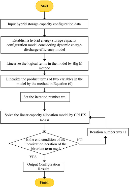
The configuration model of hybrid energy storage capacity has five types of non-convex terms as shown in Table 2, resulting in increased difficulty in optimization. In this regard, this study adopts different linearization methods for these five types of non-convex terms, as shown in Table 2 below:
3.2.2 Model Solving
According to the abovementioned linearization method, the solution process of the hybrid energy storage capacity configuration model considering the dynamic charging–discharge efficiency model is shown in Figure 3.
4 Example Analysis
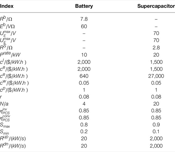
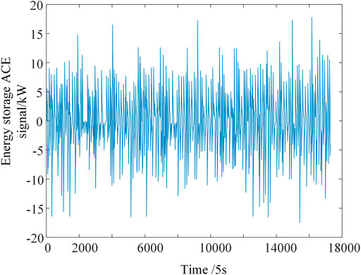
This study takes a thermal power plant with a hybrid energy storage system consisting of batteries and supercapacitors as a simulation example. The total output and ACE signal of the whole plant without energy storage on a certain day are selected, and the parameters of the hybrid energy storage system are shown in Table 3. Considering the actual operating conditions of the project-SOC differences among energy storage units, each energy storage unit is set to have SOC differences, and the initial SOC of the battery and supercapacitor is 0.4 and 0.5, respectively. The model was built and solved on MATLAB 2018b platform using YALMIP toolbox and GUROBI9.1.2 solver on a computer configured with Win10 system, AMD R7-5800H processor, and 16G RAM.
The common full compensation strategy in power plant energy storage engineering introduced by the energy storage demonstration project of Shijingshan Power Plant, which has been practiced online, is adopted: energy storage complete compensation for the difference between real-time monitoring AGC command and unit output data, namely,
To verify the effectiveness and superiority of the strategies proposed in this study,the comparison strategies shown in Table 4 is set.
4.1 Capacity Optimization Results
The purpose of capacity configuration is to ensure the frequency modulation effect of AGC and reduce the operation cost of energy storage planning. The capacity optimization results of different strategies are shown in Table 5. In energy storage output to
According to the analysis of Table 5 and Figure 5, the results are as follows:
1) The operation planning cost of strategy 1 is lower than that of strategy 2. Furthermore, the daily average ζt (0 kW) and ζt lower limit (0 kW) of strategy 1 are less than the daily average ζt (1 kW) and ζt lower limit (1 kW) of Strategy 2. Therefore, compared with single energy storage, hybrid energy storage can reduce energy storage operation planning costs and tracking error ζt;
2) The operation planning cost calculated by the scheduling model of different strategies is the expected cost value. Among them, the expected cost of strategy 3 is $5766.7, less than the planned operating cost of strategy 1 which is $13,548. Taking the capacity optimization result of the dynamic charge–discharge model as the actual value, it can be seen that the capacity optimization strategy using the constant charge–discharge model is easy to cause investors to expect too low investment costs.
3) Under the actual dynamic charge–discharge model and SOC constraints, the actual output and charge–discharge efficiency of strategy 3 are all different from those of the optimized model. In strategy 3, the actual daily average ζt (0.5 kw) is higher than the minimum value (0 kw), and there exists the ζt margin. However, in strategy 3, without considering the actual dynamic charge–discharge efficiency, the actual daily average ζt judged by the optimization model of strategy 3 is the lowest value, and there is no ζt margin. Therefore, the capacity optimization strategy of the constant charging–discharge model will lead to low prediction of tracking error of
(4) The daily average ζt of strategy 1 is the minimum, and there is no ζt margin. Therefore, the capacity optimization strategy of the dynamic charge–discharge model can improve the utilization rate of the energy storage system, fully compensate the
4.2 Analysis of Capacity Optimization Results
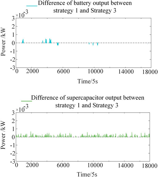
The output comparison of each energy storage unit under strategy 1 and Strategy 3 (ideal) is shown in Figure 6. It can be seen that the output results of the unit under the capacity optimization strategy of the constant charge–discharge efficiency model and the capacity optimization strategy of the dynamic charge–discharge efficiency model are similar. At this point, under the same output situation, the capacity configuration of the dynamic charge–discharge efficiency model and the constant charge–discharge efficiency model is mainly influenced by the comparison of the amount of electric quantity
Figure 7 shows the ΔE curves of Strategy 1 and Strategy 3 (ideal). As the charge–discharge efficiency of strategy 1 is lower than that of strategy 3 (ideal) in most time periods (as shown in Figure 7), ΔE of strategy 1 is higher than ΔE of Strategy 3 (ideal).
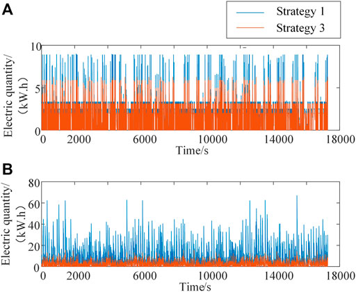
FIGURE 7. Strategy 1/3’s ΔE (A) Variation range of battery electric quantity per unit time.(B )Variation range of supercapacitor electric quantity per unit time.
In order to meet the SOC constraints of energy storage units, the capacity configuration of strategy 1 is higher than that of strategy 3 (as shown in Table 5).
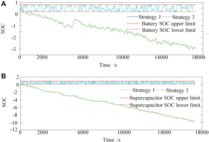
As shown in Figure 8, considering the dynamic charge–discharge efficiency model, under the capacity configuration and power allocation of strategy 1 and Strategy 3 (ideal), the SOC curve of strategy 1 or strategy 3 is shown in Figure 9. It can be seen that the capacity configuration under the constant charge–discharge efficiency model makes the energy storage system over-charge and over-discharge, and the energy storage system will exit the AGC response in some period of time, resulting in the tracking error of
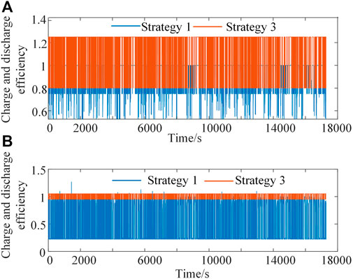
FIGURE 8. Charge–discharge efficiency of strategy 1 and strategy 3. (A) Charge and discharge efficiency of battery. (B) Charge and discharge efficiency of supercapacitor.
However, the dynamic charge–discharge efficiency model, due to the appropriately expanded capacity configuration, makes the SOC state of each energy storage unit within the constraint range, meets the continuity requirements of
To sum up, the strategy in this study takes into account the dynamic charge–discharge efficiency model and combines the characteristics of each energy storage unit to economically distribute
5 Conclusion
The combined AGC response of hybrid energy storage and thermal power unit is an effective way to improve the AGC command tracking demand of thermal power plants. In this study, a fine dynamic model of charging and discharging power-efficiency of storage battery and supercapacitor is established. On this basis, the fire-storage capacity configuration model is established, which is used to realize the corresponding capacity configuration to meet the requirements of ACE signal tracking in thermal power plants and the minimum planning and operation cost of the energy storage system. The results of examples state that
1) The dynamic charge–discharge efficiency model can avoid over-charge and over-discharge of units, improve the energy storage availability, completely compensate for the ACE signal tracking error caused by the inherent AGC response disadvantage of conventional units, and improve the AGC response performance of thermal power plants;
2) The use of the constant charge–discharge efficiency model will lead to low investment cost expectations of investors, while the dynamic charge–discharge efficiency model can more accurately evaluate the operation planning cost of hybrid energy storage.
Data Availability Statement
The raw data supporting the conclusions of this article will be made available by the authors, without undue reservation.
Author Contributions
HH determined the direction and main points of the research, HH and HW proposed the technical route of the research, HH and YC completed the writing of the research content, YC, and XC completed the simulation verification of the numerical example, and TL revised the grammar and sentence structure of the study.
Funding
This manuscript was supported in part by the Science and Technology Project of Hubei Electric Power Survey and Design Institute K2020-2-06.
Conflict of Interest
HH, HW, YC, XC, and TL were employed by Powerchina Hubei Electric Engineering Co., Ltd.
Publisher’s Note
All claims expressed in this article are solely those of the authors and do not necessarily represent those of their affiliated organizations, or those of the publisher, the editors and the reviewers. Any product that may be evaluated in this article, or claim that may be made by its manufacturer, is not guaranteed or endorsed by the publisher.
References
Aghajan-Eshkevari, S., Azad, S., Nazari-Heris, M., Ameli, M. T., and Asadi, S. (2022). Charging and Discharging of Electric Vehicles in Power Systems: An Updated and Detailed Review of Methods, Control Structures, Objectives, and Optimization Methodologies. Sustainability 14 (4), 2137. doi:10.3390/su14042137
Anderson-Cook, C. M., and Robinson, T. J. (2009). A Designed Screening Study with Prespecified Combinations of Factor Settings. Qual. Eng. 21 (4), 392. doi:10.1080/08982110903179069
Cheng, Y., Tabrizi, M., Sahni, M., Povedano, A., and Nichols, D. (2014). Dynamic Available Agc Based Approach for Enhancing Utility Scale Energy Storage Performance. IEEE Trans. Smart Grid 5 (2), 1070–1078. doi:10.1109/tsg.2013.2289380
Galatsopoulos, C., Papadopoulou, S., Ziogou, C., Trigkas, D., and Voutetakis, S. (2020). Optimal Operation of a Residential Battery Energy Storage System in a Time-Of-Use Pricing Environment. Appl. Sci. 10 (17), 5997. doi:10.3390/app10175997
Iclodean, C., Varga, B., Burnete, N., Cimerdean, D., and Jurchiş, B. (2017). Comparison of Different Battery Types for Electric Vehicles. IOP Conf. Ser. Mat. Sci. Eng. 252, 012058. doi:10.1088/1757-899x/252/1/012058
Jin, L., He, L., and Lv, R. (2022). Single-time Power Frequency Modulation and Peak -modulation Market Combined Clearing Method Considering New Energy Absorption Capacity. IOP Conf. Ser. Earth Environ. Sci. 1011, 012011. doi:10.1088/1755-1315/1011/1/012011
Liu, D., Jin, Z., Chen, H., Cao, H., Yuan, Y., Fan, Y., et al. (2021). Peak Shaving and Frequency Regulation Coordinated Output Optimization Based on Improving Economy of Energy Storage. Electronics 11 (1), 29. doi:10.3390/electronics11010029
Meng, G., Lu, Y., Liu, H., Ye, Y., Sun, Y., and Tan, W. (2021). Adaptive Droop Coefficient and Soc Equalization-Based Primary Frequency Modulation Control Strategy of Energy Storage. Electronics 10 (21), 2645. doi:10.3390/electronics10212645
Meng, L., Zafar, J., Shafiuzzaman, K., Collinson, A., Murchie, K. C., Coffele, F., et al. (2019). Fast Frequency Response from Energy Storage Systems—A Review of Grid Standards, Projects and Technical Issues. IEEE Trans. smart grid 11 (2), 1566. doi:10.1109/TSG.2019.2940173
Naseri, F., Karimi, S., Farjah, E., and Schaltz, E. (2021). Supercapacitor Management System: A Comprehensive Review of Modeling, Estimation, Balancing, and Protection Techniques. Renewable and Sustainable Energy Reviews, 2021.
Rancilio, G., Lucas, A., Kotsakis, E., Fulli, G., Merlo, M., Delfanti, M., et al. (2019). Modeling a Large-Scale Battery Energy Storage System for Power Grid Application Analysis. Energies 12 (17), 3312. doi:10.3390/en12173312
Saxena, A., and Shankar, R. (2022). Improved Load Frequency Control Considering Dynamic Demand Regulated Power System Integrating Renewable Sources and Hybrid Energy Storage System. Sustain. Energy Technol. Assessments 52, 102245. doi:10.1016/j.seta.2022.102245
Song, C., Feng, J., Yang, D., Zhou, B. W., and Qi, G. (2018). Collaborative Optimization of Integrated Energy Considering System Coupling. Automation Electr. Power Syst. 42 (10), 38. doi:10.7500/AEPS20170914008
Sun, B., He, X., Zhang, W., Li, Y., Gong, M., Yang, Y., et al. (2020). Control Strategies and Economic Analysis of an Lto Battery Energy Storage System for Agc Ancillary Service. Energies 13 (2), 505. doi:10.3390/en13020505
Wang, H., Wang, T., Xie, X., Ling, Z., Gao, G., and Dong, X. (2018). Optimal Capacity Configuration of a Hybrid Energy Storage System for an Isolated Microgrid Using Quantum-Behaved Particle Swarm Optimization. Energies 11 (2), 454. doi:10.3390/en11020454
Yang, N., Dong, Z., Wu, L., Zhang, L., Shen, X., Chen, D., et al. (2021). A Comprehensive Review of Security-Constrained Unit Commitment. J. Mod. Power Syst. Clean Energy 10 (3), 562–576. doi:10.35833/MPCE.2021.000255
Yang, N., Yang, C., Xing, C., Ye, D., Jia, J., Chen, D., et al. (2022). Deep Learning‐based SCUC Decision‐making: An Intelligent Data‐driven Approach with Self‐learning Capabilities. IET Generation Trans Dist 16 (4), 629–640. doi:10.1049/gtd2.12315
Yang, R. (2016). Design And Optimization of Hybrid Energy Storage for Photovoltaic Power Fluctuation Smoothing Based on Frequency Analysis. PhD Thesis. The University of Wisconsin-Milwaukee.
Ye, J., Zhao, D., Zhang, L., Li, Z., and Zhang, T. (2021). Research on Combined Electricity and Heating System Scheduling Method Considering Multi-Source Ring Heating Network. Front. Energy Res. 826, 906. doi:10.3389/fenrg.2021.800906
Zhang, F., Yang, Z., Wang, G., and Meng, K. (2018). “Control Strategy of Hybrid Energy Storage System to Improve Agc Performance of Thermal Generator,” in 2018 IEEE Innovative Smart Grid Technologies-Asia (ISGT Asia) (IEEE), 1299–1304. doi:10.1109/isgt-asia.2018.8467771
Keywords: energy storage-thermal power combination, AGC response, hybrid energy storage system, capacity configuration, dynamic efficiency
Citation: Huang H, Wang H, Cai Y, Chen X and Li T (2022) Optimal Configuration of Fire-Storage Capacity Considering Dynamic Charge-Discharge Efficiency of Hybrid Energy Storage. Front. Energy Res. 10:950521. doi: 10.3389/fenrg.2022.950521
Received: 23 May 2022; Accepted: 13 June 2022;
Published: 22 July 2022.
Edited by:
Xun Shen, Tokyo Institute of Technology, JapanReviewed by:
Sandeep Kumar Duran, Lovely Professional University, IndiaGaurav Sachdeva, DAV University, India
Copyright © 2022 Huang , Wang, Cai, Chen and Li. This is an open-access article distributed under the terms of the Creative Commons Attribution License (CC BY). The use, distribution or reproduction in other forums is permitted, provided the original author(s) and the copyright owner(s) are credited and that the original publication in this journal is cited, in accordance with accepted academic practice. No use, distribution or reproduction is permitted which does not comply with these terms.
*Correspondence: Hongbo Huang, eDk5NzA1MDAzNUAxNjMuY29t
 Hongbo Huang
  Hui Wang