 S. Shanmugam
 A. Sharmila
- School of Electrical Engineering, Vellore Institute of Technology, Vellore, Tamil Nadu, India
The increasing significance of renewable power systems with diverse sources has produced an unexpected demand for electronic converters to integrate and simultaneously control, various energy resources, and storage devices. The voltage-current characteristics and the voltage levels of storage, as well as energy generating systems, are naturally diverse from those of loads. Hence, converters are employed to transform the energy from the renewable power plants to meet the total power demand, to enable the renewable energy system to use Maximum Power Point Tracking algorithm, to enhance the dynamic and static characteristics of the system, and to integrate the energy storage devices to resolve the issue of the irregularity of the load demand and unstable characteristics of the renewable sources. The implementation of a Multiport DC/DC converter (MDC) is a viable solution to increase the system efficiency and power density. The conventional MDC contains 1) DC unidirectional input ports to connect the renewable energy generating system; 2) two-way input ports to interface battery like storage devices; and 3) output ports to interface the load. Recently, numerous multiport converter configurations have been developed and described in the literature. Each of these reported MDCs has distinct architecture and working mechanism, which leads to a diverse level of intricacies, different component count, different performance, and reliability. This paper reviews various configurations of MDCs that have been introduced by different research communities to integrate solar energy with Battery Storage System (BSS). Different MDCs topologies such as partially-isolated, isolated, non-isolated configurations are discussed according to their physical structures and other aspects. This article can be employed as a guideline to select the appropriate configuration to match the certain condition of a system.
1 Introduction
A profound energy transformation is happening at a global level, impelled by the dual constraints of fostering sustainable growth and controlling climate change. According to the data in the new report received from the International Energy Agency (IEA), the number of individuals does not have access to electrical energy has dropped to approximately 840 million (i.e., 13% of the world population) from 1 billion (i.e., 15%) in 2016 and 2. billion (i.e., 20%) in 2010 (• Chart: Electricity Access Keeps Climbing Globally | Statista). The critical energy crisis and severe pollution issues, an extraordinary drop in levelized costs of renewable energy, improvements in energy efficiency, digitalization, and electrification solutions are the significant facilitators for this development. By 2050, the proportion of electrical energy in overall energy utilization must rise to nearly 50%, up from 20% at present. Renewables would then contribute two-thirds of energy ingestion and 86% of energy generation. Deep electrification coupled with renewable energy generation could decrease greenhouse gas emissions by 60%, indicating the biggest part of the cutbacks required in the energy industry (IEEE Power Electronics Society et al., 2017).
Currently, Solar Photovoltaic (SPV) generation is emerging as an attractive alternative to conventional energy sources (fossil fuels) due to its reduced cost of energy, scale flexibility, ease of procurement, demand for little maintenance, and quiet as well as pollution-free operation (Ieee and Ieee, 2012). However, garnering energy from highly intermittent and unpredictable SPV systems is profoundly reliant on environmental conditions such as ambient temperature, level of solar radiation, and unstable shadows. Hence, SPV generation should be complemented by other suitable generating systems (e.g., wind, fuel cells, biomass, etc.) and energy storage systems (e.g., supercapacitors, battery, etc.) for delivering reliable and uninterrupted supply to the load. The storage schemes are required to hoard the surplus power in the high radiation time and meet the power demand of the load if the renewable source is not adequate or not existing to meet the power demand of the load.
Batteries are widely used storage systems for regulating power output, enhancing dynamics of energy transitions, and improving the maximum generating capacity of the renewable electricity generation systems (Chen et al., 2015; Mira et al., 2017). Integrating such renewable energy sources Three Port Converter (TPC) with BSS provides an integrated power system. These systems enable more efficient, reliable, and high-quality energy services as compared with single-sourced systems. In such a system, the ability of two-way energy distribution is a significant aspect. Also, the energy resources should have the capacity of supplying the load independently as well as cooperatively. Besides, multiport converters are required for interfacing SPV systems and fuel cells with the load to match the load and grid demand, for providing MPPT control, and also for increasing the steady-state as well as dynamic characteristics of the energy resources (Madhana and Mani, 2022).
Conventionally, the renewable power generating system requires 1) a pre-conditioning DC/DC converter (DDC) to enable better isolation, provide constant power output, and also accomplish full energy garnering; and 2) two unidirectional or a single two-way converter to adjust the charge and discharge rate of battery (Xie et al., 2010; Subramanian and Santha, 2020). Figure 1A illustrates a renewable energy application with multiple unidirectional DDCs. The major drawback of this classic method is its poor performance owing to the usage of the supplementary converter for interfacing the BSS. Besides, the multi-stage configuration may cause bigger size, higher cost, and comparatively lower power density.
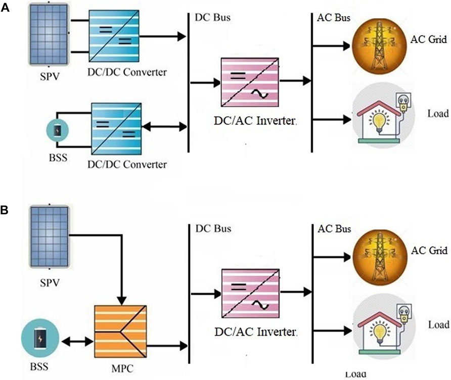
FIGURE 1. Configurations of DDC. (A) Renewable energy application with multiple unidirectional DDCs. (B) MDC with two input ports.
Utilizing an MDC is a sustainable way to meet the load demands in some applications that need the combination of multiple input energy sources (Qin et al., 2014). The integrated MDC, rather than multiple individual converters, has benefits including a smaller number of conversion stage and circuit elements because storage devices and switching elements are pooled for every transition epoch. Furthermore, some additional benefits of integrated MDC are better reliability, lower cost, and improved dynamic characteristics owing to centralized control and power stage integration. Also, it needs no communication competencies that would be essential for a system with several independent converters. Consequently, the communication error and latency can be circumvented with this integrated configuration. Even though these converters are employed to meet the load demand with only one conversion phase, no battery pack is incorporated. Therefore, the system may not be capable of matching the load requirements if the required power is greater than the output power of the generating system. For SPV implementation, there is a swift yield variation when passing clouds instigating the productivity to be lower than the load requirement or if there is no solar radiation at nightfall. Hence, a BSS is required to incorporate into the system to match the power demand of the load while the external grid or renewable energy system does not supply adequate demand.
In recent years, numerous MDCs have been developed to assimilate the SPV plant and a suitable BSS. As shown in Figure 1B, an MDC contains two input ports: 1) A unidirectional port for DC output from the SPV system; and 2) a two-way port for interfacing BSS. The output port of the MDC is coupled to the central grid or the load directly. Several MDCs, which can meet power-storage demands, have been stated in the literature that leads to an expansive range of topologies. The architectures of MDCs can be characterized into three types: Partially-isolated, isolated, and non-isolated configurations. Non-isolated MDCs have gained much more attention from researchers by providing a compact architecture with a reduced number of circuit elements (Wu et al., 2011c; Phattanasak et al., 2011; Chen, 2014; Samavatian et al., 2014; Zhang et al., 2014). As all the ports are coupled directly, this kind of MDC is merely employed in those applications where strong isolation is not mandatory (Qin et al., 2014). One more shortcoming of this MDC is that majority of them offer an inadequate conversion ratio because the freedom of voltage modulation is equal to the duty ratio. To increase this ratio, some researchers use a coupled-inductor (Wu et al., 2011b; Qian et al., 2011).
The partially isolated converters use a transformer to achieve insulation among ports and to realize higher voltage gains. On the other hand, the BSS used in this topology remains functioning in all operating states, which can reduce the lifecycle and reliability of the storage device. The isolated converters also use High-Frequency Transformers (HFT) to stabilize the voltage levels in various ports (Parthiban and Rajambal, 2014). Nevertheless, the component count related to this topology is very high as the circuit resources are occasionally shared. Though the partially isolated and isolated MDCs are activated by soft-switching techniques via suitable modulation and control strategies, higher power loss is remains experienced owing to the transformer leakage inductance. Similarly, the utilization of a transformer makes the system sizeable and decreases the energy efficiency. This article delivers a comprehensive assessment of MDCs introduced by diverse research communities for assimilating SPV with an appropriate BSS. The remainder sections of this article are arranged as: Section 2 explores the common operating states of the MDC. Section 3 describes the possible topologies of DC/DC power converters available in the literature. Section 4 presents a brief introduction to MDCs. Section 5 detail the recent studies on non-isolated, partially isolated, and isolated MDCs. Finally, we conclude this paper in Section 5.
2 General operating states of multiport converters
The key objective of using MDC is to assimilate several renewable resources and energy storage systems into a single conversion phase enabling energy distribution amongst ports. Figure 2 illustrates the common functional states of a grid-connected arrangement with usual everyday power profiles. This system assimilates an SPV energy generating system, optimized power grid, residential building load, and BSS using an MDC.
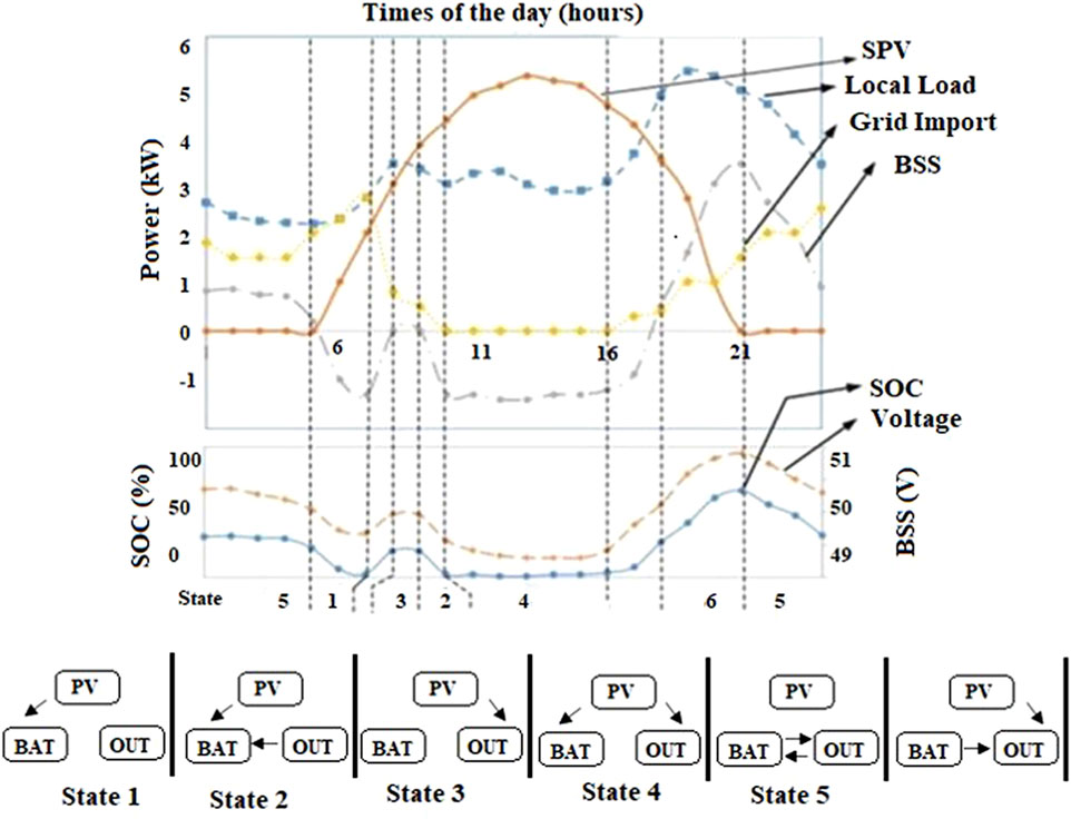
FIGURE 2. Operating modes of MDC. Different power distribution modes are achieved for various operating states of the MDC.
The optimization of the grid profile aims at minimizing the total costs of energy during off-peak and peak periods. According to the power distribution, the BSS voltage and State of Charge (SOC) are also charted to display the charging and discharging operation. The battery C-rating is selected as 1C which represents the charging and discharging rate of the BSS. This denotes that a completely charged BSS rated at 2 Ah should deliver 2 A for 1 h. Different power distribution modes are achieved for various operating states of the MDC as illustrated in Figure 2.
To assess the effectiveness of the integrated SPV-BSS arrangement, we considered a Lithium-ion battery with an SPV. The entire power distribution of the SPV-BSS integration system is expressed by Eq. 1.
where
For a grid-tied environment, it is expressed as
The most common power flow modes and corresponding operating states are described below,
• Peak shaving mode (between operating states 1 and 2 or between states 4 and 5): In this mode, the BSS will consume energy from the grid during the off-peak period or when SPV is generating surplus power and discharge the power during peak loads.
• PV firming mode (combination of operating state 4 and operating state 6): In this mode load or grid receive power either from SPV or BSS integration or both.
• BSS charging mode (at operating state 2 and state 4): In this mode, the BSS system is charging either from SPV or grid.
Several control approaches can be used depending on the operating states of the multiport converter (Zhu et al., 2015a), but, the power distribution among various ports also acts as a vital role in choosing the structure of the converter to be employed. With the reducing cost of energy storage and the greater applicability of renewable energy sources, several protocols are either boosting or directing the utilization of BSS for peak shaving, SPV firming, and secondary services such as voltage and frequency control, which can also be realized by integrating these functional states. For instance, operating state 4 needs an energy transmission from SPV to load/grid and energy transmission from SPV to BSS. In this scenario, the multiport converter must restrict distribution between the BSS and the grid/load, from BSS to SPV, and from the grid to SPV completely. This restriction can be realized by a reverse blocking diode connected with the SPV. This method limits the power transaction to the SPV by turning out the converter located between SPV and BSS. It is noteworthy that two-way energy transaction needs a suitable control mechanism to provide continuous transition between the functioning states. Enabling transition among different operating modes for the two-way ports is a perplexing endeavor (Tao et al., 2008; Krishnaswami and Mohan, 2009).
3 Possible configurations for power converters headings
Several DDC configurations are reported in the literature to assimilate SPV and BSS (Qian et al., 2009; Falcones and Ayyanar, 2010; Wu et al., 2011b; Zhang et al., 2014; Bhaskar et al., 2020). Figure 3. illustrates four widely used configurations for combining SPV array and BSS. The red arrows signify the power flow direction. Figure 3A shows a dual-converter architecture which consists of a distinct DDC for the SPV array and BSS modules with an additional DC/AC inverter (al Shaqsi et al., 2020; Mexis and Todeschini, 2020). Figure 3B shows another prevalent design, a single two-way converter architecture that consists of a BSS with the DC link configuration, where a DC/DC converter to connect BSS is excluded (Rehman et al., 2015). Figure 3C depicts a dual-inverter configuration to incorporate the BSS into the AC side by means of a distinct inverter. These configurations have their own merits as well as drawbacks. To study these configurations, a classic 300 W integrated SPV-BSS configuration and a load is considered. The ratings of the SPV array and BSS are selected from real-world and off-the-shelf components available in the market.
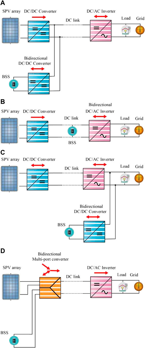
FIGURE 3. Different Multiport topologies integrated with grid. (A) A Dual-converter architecture which consists of a DDC and additional DC/AC inverter for the SPV array and BSS modules (Shaqsi et al., 2020; Mexis and Todeschini, 2020). (B) A single two-way converter architecture with BSS and DC link configuration (Rehman et al., 2015). (C) Dual-inverter configuration to interconnect the BSS and AC Grid with inverter. (D) Standalone or grid-connected SPY BSS system (Bayat and Baghramian, 2020).
The configuration in Figure 3A is the extensively acceptable choice as the intermediary DDC can step up the BSS voltage into a high-tension DC-link attuned with the AC link. Configurations in Figures 3B,C are appropriate for a high voltage BSS, whereas the architecture in Figure 3B demands extra relays and control devices to transfer energy from SPV to BSS or SPV to load without distressing the other port. However, this trapping presents dependability problems and system loss. Furthermore, it is observed that this configuration is not appropriate for the 48 V BSS as its rating is extremely small to be joined to the high-tension DC link directly. In this configuration, in order to preserve grid synchronization, we need a suitable inverter according to the rating of the BSS since it is unrestrained as well as coupled to the DC link directly. The inverter specification is based on the type of configuration used. For example, the rating of inverter used in single two-way converter architecture is 300 W. Whereas, the rating of both inverters used in the dual-inverter configuration is 300W, consequently increasing the system cost. Furthermore, for the same configuration, assimilation of BSS is assumed as an isolated system, necessitating a promising protection circuitry to be implemented to the BSS port as it is coupled at the common coupling point directly. In this case, the BSS can be employed as an autonomous system. The MDC presented in Figure 3D resolves several challenges imposed by the above-mentioned configurations, and consequently provides feasible solutions to the standalone or grid-connected SPV-BSS system (Bayat and Baghramian, 2020).
The voltage and size of the battery are no longer calculated by the DC link. Moreover, the selection of particular topology is extremely flexible and exploits fewer circuit elements to realize the same enactment as configurations in Figures 3A,B, therefore improving power density and system performance. Recent studies proved that the multiport converter configuration (refer to Figure 3D) has fewer components and is very compact with a single conversion stage (Wang and Nehrir, 2008). Indeed, MDCs reduce reduction control complexity considerably hence it achieves improved system flexibility.
4 Multiport DC/DC converters
Of late, numerous MDCs have been reported in the literature. They have the benefits of higher power density and higher efficiency. The main issue with multiport converters is that certain designs have more components, more switching lossless and hence worse efficiency while yet having a high voltage gain. Other topologies feature lower voltage gain, no power decoupling, and should have a reduced switch count and greater efficiency. As a result, topologies are chosen with cost and efficiency in mind. This type of converters is a desirable choice for unraveling the problems that are created by the unpredictability of the load demand and the unstable nature of the renewable resources, by integrating BSS as a supplementary DC input. MDCs are categorized into three important classes based on the connection between the ports: 1) Non-Isolated MDC (NIMC), 2) Partially Isolated MDC (PIMC) (Duarte et al., 2007; Riffonneau et al., 2011; Ding et al., 2013; Sun et al., 2014a; McDonough, 2015), and 3) Isolated MDC (IMC) (Krishnaswami and Mohan, 2009; Wu et al., 2013; Zhu et al., 2015a; Charles Rajesh Kumar and Majid, 2020). In NIMC, all the ports are coupled directly without any strong isolation as given in Figure 4A, which leads to a compact structure with higher power density. A HFT is used in the IMC and PIMC to provide galvanic isolation between ports as shown in Figures 4B,C, respectively. The transformer is also employed for increasing the gain of the converter. On the other hand, the application of HFT increases the dimension and consequently decreases the converter efficiency and the power density as related to non-isolated MDCs. In consort with appropriate energy management approaches and modulation techniques, these MDCs are used to meet the load demands of certain industries.
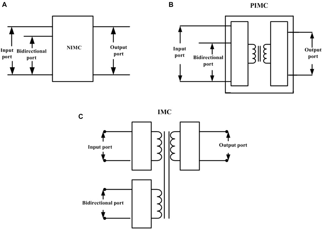
FIGURE 4. Types of multiport converter topologies. (A) Non-Isolated MDC (NIMC), (B) Partially Isolated MDC (PIMC), (C) Isolated MDC (IMC).
4.1 Non-isolated multiport converters
Most of NIMCs are derived from traditional boost, buck, and buck-boost converters, but they perform unidirectional power flow at the load port with different modulation and control strategies. Some NIMCs use a single inductor to provide compact topology and auxiliary enhancement in power density characteristics whereas others use more than two inductors. The basic structures of these cells are given in Figure 5.
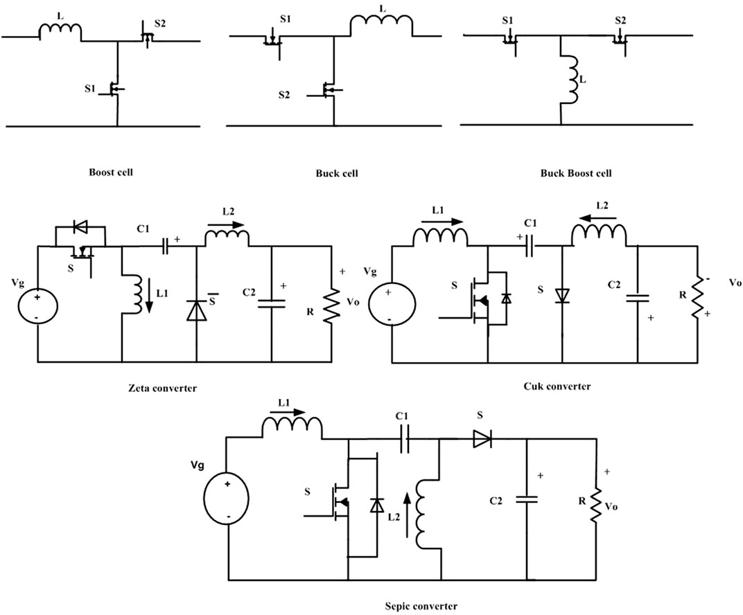
FIGURE 5. Basics cells.
(Wu et al., 2013) proposed presented a technique to derive non-isolated TPC topologies using dual-input and dual-output converters that are connected to a load, a storage battery, and a renewable energy source. High integration, high efficiency, and single-stage power conversion are all features of this topology. Additionally, the original TPC topologies were made as effective as feasible by combining and integrating power flow channels to share active and passive components as much as possible while maintaining complete control over each power flow path. The sample structures of deduced NIMCs are shown in Figure 6A.
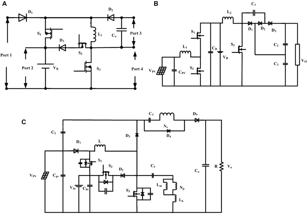
FIGURE 6. TPCs derived from basics cells. TPCs derived from (A) Boost-Buck/Boost-DOC boost three port MDC proposed by (Wu et al., 2013). (B) A novel three-port converter proposed by (Zhang et al, 2015). (C) Novel three-port converter with high voltage gain proposed by (Chien et al., 2014).
Bowen Zhang et al.,2017proposed a novel three port converter for stand-alone Photovoltaic (PV) power, and also presented the control strategy and power management of this converter as shown in Figure 6B. This converter uses three power switches, two inductors, and a switched capacitor structure to obtain a higher voltage gain and reduce the voltage stress of the power switches. The control for the converter has been proposed for realizing MPPT, battery protection, and output voltage regulation simultaneously. Also, the controllers are not connected to each other, so they can automatically switch between different modes of operation. For applications involving independent renewable power systems (Chien et al., 2014), presented a revolutionary three port converter with high-voltage gain as shown in Figure 6C. This converter controls power flow with simply three switches. One inductor is shared by two input sources. Therefore, the volume can be decreased. In addition, the converter has a greater conversion rate than other converters. Thus, the duty cycle’s degree of freedom is expansive. With a reduced turn ratio and an appropriate duty ratio, the voltage gain of both low-voltage ports of the converter can be increased. Therefore, low Rds (on) switches can be used to further reduce conduction loss, given the low voltage stress of switches. Therefore, the converter may achieve both a high conversion rate and great efficiency. For better battery management (Zhu et al., 2015b) suggested three-domain control for a new three-port dc/dc converter with no isolation called a boost bidirectional buck converter. Depending on how much power is made by the sun, how much power is needed by the load, and what the battery management command is, the power system will work in either MPPT mode or conductance mode, and it can switch between the two modes on its own. Also (Alves et al., 2015) suggested a three-port dc-dc high voltage gain boost converter for battery charging employing PV modules in a single conversion step as shown in Figure 7A. The given converter can deliver a 200-V dc-link utilising a battery bank and a PV array. Depending on solar irradiation, the batteries can also be charged in a single stage. All converter switches can work in ZVS mode across a broad range (Zhou et al., 2012). proposed a novel non-isolated TPC with PV, battery, and load ports. Single stage power conversion between two ports and decoupling the traditional structure’s bidirectional power flow line into two unidirectional ones creates the topology as shown in Figure 7B. A revolutionary three-input dc-dc boost converter with a unified topology suggested by (Nejabatkhah et al., 2012) that interfaces two unidirectional input power ports and a bidirectional port for a storage element using just four independently controlled power switches with four variable duty ratios as shown in Figure 7C. Using these duty ratios, the maximum power of the PV source is tracked, the FC power is set, the battery power is controlled, and the output voltage is regulated. Two of the three ports can be closely regulated to maximize PV power harvesting or battery charge management, while the third port is kept flexible to compensate for the converter’s power imbalance. It works both the state dual input as well as dual output.
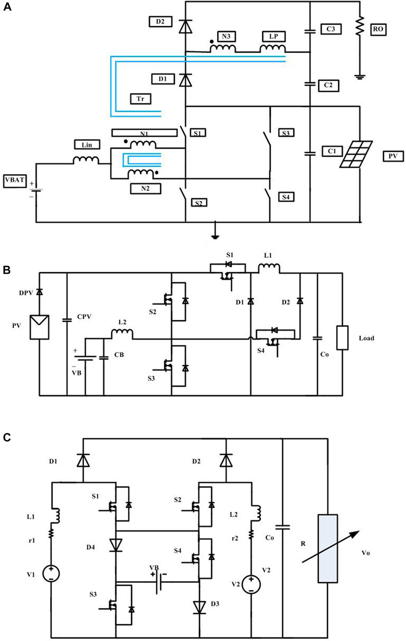
FIGURE 7. NIMCs derived from switched Inductors and capacitors. (A) A novel non-isolated three port MDC (Alves et al., 2015), (B) A novel non-isolated three port MDC proposed by (Zhou et al., 2012). (C) A four part non isolated multi input single output DC-DC converter (Nejabatkhah et al., 2012).
(Zhang et al., 2015) developed a novel non-isolated TPC based on the classic Boost converter, which can be used to connect the PV panel and the load. However, to build a new bidirectional path for battery energy extraction, a coupling winding to the existing single inductor and a diode are added, and hence the topology becomes a Single Inductor-Dual-Output (SIDO) converter. This derivation uses the fewest components, and its three ports share a common ground. This implementation reduces the number of parts, keeps the feature that all three ports have in common, and still makes sure that all three ports are fully controlled.
(Balaji et al., 2017)presented a four-port DC-DC converter for electric vehicle applications that incorporate renewable energy sources and energy storage devices. The converter has two inputs, one bidirectional port, and one output. The charging, discharging, and disturbance states at the input side are all regulated, and this architecture may operate in three main operating modes: single-input-single-output (SISO), Double Input Double-Output (DIDO), and triple-input-single-output (TISO).
A three port MDC derived from buck-boost converter with a high step-up/step-down capacity proposed by (Chandrasekar et al., 2020) as shown in Figure 8A. It includes two unidirectional and one bidirectional charging port for solar energy. A specific configuration of switches and inductors is employed with the combined structure of buck and buck-boost converters. The voltage conversion ratio is greater than that of a traditional buck-boost converter with a simple control strategy. For hybrid applications (Faraji et al., 2021), developed a novel Non-Isolated TPC made use of boost converter topology and proved with high efficiency as shown in Figure 8B. The traditional TPC topology is modified by changing its structure and adding a simple auxiliary circuit so that all switches operate in a soft-switching mode in all operating modes. For traction application (Suresh et al., 2021), presented a single-stage four-port non-isolated buck-boost converter. During its operation, the proposed topology may produce both a buck and a boost output. and accomplished with a decreased component count and a simpler control technique, resulting in a more dependable and cost-effective converter as shown in Figure 8C. Furthermore, this converter has bidirectional power flow capabilities, making it useful for charging an electric vehicle’s battery during regenerative braking.
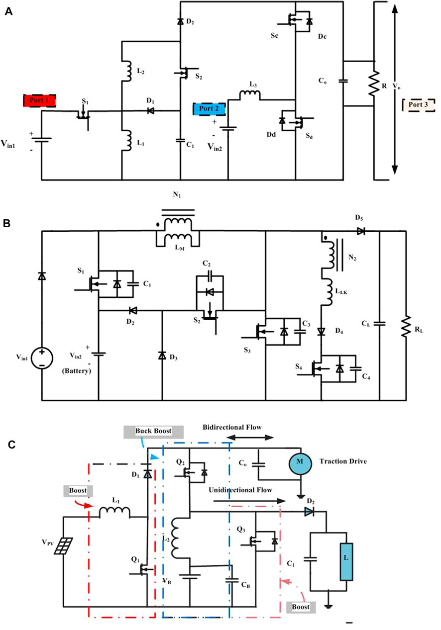
FIGURE 8. Modified MDCs derived from Basics cells. (A) Three port MDC derived from DC-DC buck-boost converter (Chandrasekar et al., 2020). (B) Three port MDC derived from DC-DC boost converter (Faraji et al., 2021). (C) Topology of four port converter (FPC) derived from boost and buck-boost converters (Suresh et al., 2021).
For battery ESS integrated PV systems (Wang et al., 2022), developed a Multi-Port DC-AC converter (MPC) with Differential Power Processing DC-DC Converter (DPPC). Only the differential power (partial power) has to be handled by the dc-dc converter since the MPC can control the most active power among PV, battery, and ac grid. As a result, the suggested design may accomplish the key benefits of better integration, higher efficiency, and reduced cost. A new cooperative control technique for the MPC and DPPC is studied in order to provide flexible active power flow. Furthermore, a modified space vector pulse-width modulation (SVPWM) is designed for the MPC, taking into account the voltage changes of both the PV and the battery. Table 1 presents a thorough list of significant metrics of the studied topologies, allowing for a better understanding of how each topology compares to others based on power rating, voltage rating, derivation of topologies, voltage gain and device count, efficiency, etc.
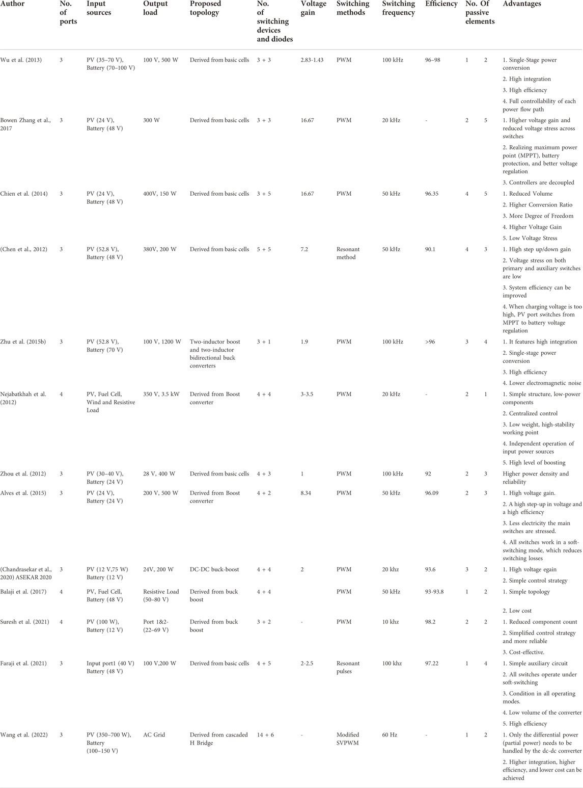
TABLE 1. Parameters comparison in Non-Isolated Topologies.
4.2 Partially isolated multiport converters
In general, PICS galvanic isolation. In case of PIC, either all input ports should be connected with RESs or the combination of RESs and Bidirectional port for energy storages. Similarly, output ports either all should be load ports or the combination of load and bidirectional port for energy storage. A brief survey all such types of PICs are discussed here. some PICs topologies are made using full bridge converter with different switching control (Qian et al., 2011), proposed a PWM with Secondary-Side Phase-Shift-Controlled (PWM + SSPS) Full-Bridge TPC (FB-TPC) as shown in Figure 9A. It integrates two Buck-Boost converters into the primary side of the full-bridge topology and substitutes two diodes in the secondary full-bridge rectifier with two active switches in order to supply steady and continuous power to the load. In addition, centralized control is implemented to improve dynamic performance and increase reliability by eliminating complicated communication devices. Also (Sun et al., 2014b) proposed an interleaved bidirectional Buck/Boost circuit with a three-port full-bridge LLC resonant circuit for a standalone PV/Battery system as shown in Figure 9B. This design produces a small input current ripple, which is advantageous for interfacing renewable energy sources.
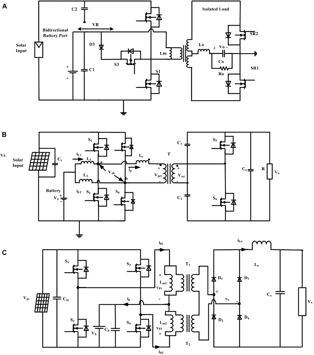
FIGURE 9. Different PIMCs based on full bridge. (A) PWM with secondary-side phase-shift-controlled (PWM+SSPS) full-bridge three-port converter (FB-TPC) (Qian et el., 2011). (B) An interleaved bidirectional buck/boost circuit with a three-port full-bridge LLC resonant circuit (Sun et al., 2014b). (C) A three-port converter from full-bridge (Hu et al., 2014).
But (Mira et al., 2017) presented an isolated TPC consists of interleaved-boost full-bridge converter with PWM and Phase Shift control (PS). Primary-side MOSFETs may accomplish Zero Voltage Switching (ZVS) without extra circuitry. Due to the ac output inductor, secondary-side diodes can work under Zero Current Switching (ZCS). A systematic approach to derive a TPC from the Full-Bridge topology proposed by Wu et al. (2012). He accomplishes this by dividing the two legs of full bridge into two switching cells and connecting them to two different sources. To configure the power flow, a buck-boost converter is integrated with this arrangement. (Hu et al. (2014) proposed FB-TPC incorporates two Buck-boost converters onto the primary side of a full-bridge topology, and the transformer’s magnetizing inductor works as an inductor as shown in Figure 9C. The duty cycle of the buck-boost converter is used to track the maximum power point of the PV cell and regulate battery charging. To further regulate the output voltage, the phase angle between the two switching legs is controlled. To reduce switch count instead of full bridge, PICs also made of half bridge converter (Wu et al., 2011a), describe the various methods to derive three-port half-bridge converters with the merits of simple topologies and control, a reduced number of devices, and single-stage power conversion between any two of the three ports for a standalone application.
(Qian et al., 2010) designed a closed loop control for modified version of pulse width modulated (PWM) half-bridge converter using state-space averaging method. This converter model operated under different modes of operation with proper decoupling network. And it allows control loops to operate independently with each other and (Zhang et al., 2014) proposed an integrated and flexible TPC for DC distributed power systems that is built using a modified PWM half-bridge converter with secondary synchronous rectification. Some fundamental guidelines will be observed when taking the battery’s charging state into account for the DC Distributed Power System’s stable and reliable operation. The author suggested three control strategies, such as Master-slave control, Fixed-proportion control, and Ability of Source (AOS)-based-proportion control, in accordance with these rules, but each has some drawbacks. As a result, he once more proposed Hybrid Power Flow Distribution Control, which eliminates all drawbacks and achieves steady operation in each mode as well as a smooth transition between various modes.
(Qian et al., 2009) proposed a novel TPC topology made of a constant frequency modified PWM half-bridge converter. Two of the three ports can be controlled simultaneously. However, these control loops have interactions with each other due to the integrated power trains of the three ports. Therefore, careful attention is needed to analyses their dynamic behaviors. According (Zhu et al., 2015a) creating a novel topology that comprises of a half-bridge topology, an input boost converter that functions as a magnetic switch, and an energy balancing component made up of the boost converter is explained. The constant input current to the solar array is maintained by a magnetic switch created from the fourth winding of the half-bridge transformer.
Additionally, the power system control technique for multimodule in parallel is derived, and the TPC power system’s operation may switch automatically between conductance mode and MPPT mode. Originally PICs proposed by using Dual Active Bridge (DAB) with some basic converter cells like boost, buck and buck boost cells to integrate the bidirectional ports by (Wang and Li, 2013) suggested a three-phase DAB converter to realize the bidirectional power flow function in an integrated three-port bidirectional dc-dc converter for a DC distribution system. The proposed converter’s high-frequency transformer not only offers galvanic isolation between energy sources and the high-voltage DC bus, but it also aids in the removal of leakage current caused by PV panels.
And also (Sun et al., 2014a) proposed Dual Buck/Boost integrated three-port bidirectional DC/DC converter incorporates with DAB and two bidirectional Buck/Boost circuits. Interleaving the input inductors reduces input current ripple. Phase-shift plus PWM control Buck/Boost circuits provide bidirectional power flow between any two ports. And a Split DC-Link Dual-Active-Bridge Based Multiport Converter (MPC) is proposed by (Vettuparambil et al., 2022) is interfaced with two solar PV modules and a battery bank with by a DC microgrid illustrated in Figure 10A. These two solar PV modules are operated at their maximum power points. This is achieved by maintaining appropriate voltages at the input terminals. A direct power flow path is established between the solar PV modules and the battery without involving the transformer. An optimization method to adopted minimize the transformer current. In order to get higher volage gain and reduced switching losses (Bayat and Baghramian, 2020), presented a brand-new PIC based on a quasi-Z source converter. It uses switched capacitors and coupled inductor methods for their input sources, which aids the converter in gaining a high voltage and efficiency for photovoltaic applications. An improved topology for the standalone photovoltaic system was made out by (Nakayama Hiroaki et al.). It is made up of the PV modules, two Step-Down Converters (SDC1 and SDC2), and combined storage made up of parallel-connected EDLC and lead batteries as shown in Figure 10B. The combined storage device is used to store the electrical energy produced by the solar cells, which is MPPT-controlled and managed by SDC1. SDC2 regulates and supplies the stored power to the DC load. Based on an enhanced Flyback-Forward topology (Hu et al., 2015), addressed TPC system performance and cost effectiveness as shown in Figure 10C. It provides a compact single-unit solution with MPPT, high step-up ratio, galvanic isolation, and different working modes for residential and aeronautical applications. A three-port DC-DC converter was proposed by (Chen et al., 2015). It is a conventional flyback converter with just two ports, but a third “ripple” port has an extra circuit attached to it to smooth out the ripple in the low-frequency current. Detailed features of above-mentioned PICs topologies are configured in Table 2. It also points out the advantages of PICs topologies. Obviously, it is clear that for medium voltage and power applications PICs topologies are superior than NICs.
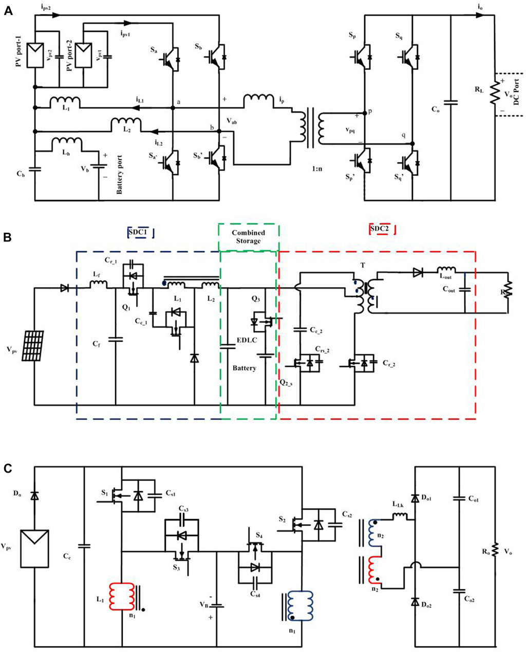
FIGURE 10. Improved PIMCs topologies. (A) A split DC-link dual-active-bridge based multiport converter (Vettuparambil et al.,2022). (B) An improved topology for the standalone photovoltaic system with two step-down converters (SDCI and SDC2) (Nakayama and Hiraki, 2008). (C) An enhanced flyback-forward topology (Hu et al., 2015).
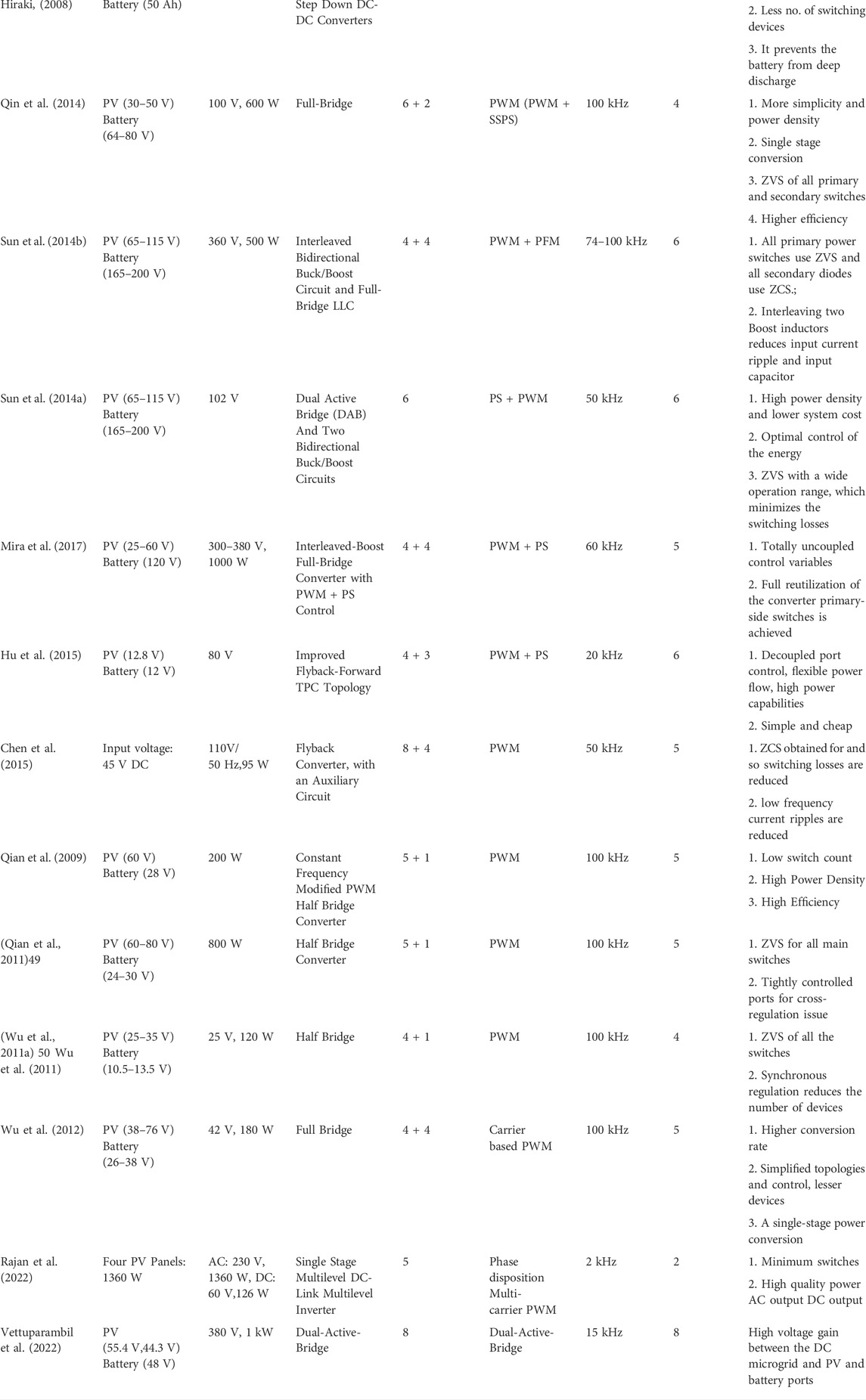
TABLE 2. Important features of reported partial isolated topologies.
4.3 Isolated multiport converters
Isolated topologies use multi-winding or multi-transformers connected between high-frequency ports, with the number of ports determined by the number of windings of the high-frequency transformer. It acts as a galvanic isolation barrier between the ports. For power conversion, a full-bridge, half-bridge, or a combination of both topologies are used with a transformer. A phase-shifting technique is used to transmit active power between their ports. According to the phase-shifting principle, the power transfer between the ports a and b (
Where
(Jiang et al., 2014) proposed an optimal idling control strategy for three-port full-bridge converter, which focuses on the minimum conducting losses under different operation conditions by applying the phase-shift plus PWM control strategy as shown in Figure 11A. in addition to the phase-shifting principle for power transfer, the author included a PWM technique to increase the efficiency. To speed up the fuel cell stack’s sluggish transient response (Duarte et al., 2007), developed a three-full-bridge IMC design. This system has applications in autonomous devices experiencing rapid changes in load. The proposed design enables power to flow in both directions through each port. Such a setup makes it easier to equalise the system’s various voltage sources. The power flow control uses a feedforward method to evenly distribute energy and a closed-loop strategy to maintain a stable output voltage during transients. Krishnaswami and Mohan (2009) proposed a three-port full-bridge topology with two series resonant tanks in series with a high-frequency transformer to interface renewable energy sources and the load, along with energy storage as shown in Figure 11B. When comparing the TPC with mere inductors, the use of series-resonance helps in high switching frequency operating with realizable component values. Since all three bridges in the converter use soft switching, it is quite efficient. The power flow between ports can be controlled by series resonance and phase-shifting the square wave outputs of the three active bridges. Phattanasak et al. (2011) evaluate and contrast two nonlinear control algorithms for an isolated three-port bidirectional full-bridge DC-DC converter. The dynamic response of the first control method, which consists of a nonlinear and a PI controller, varies with the operating point. The second technique for control relies on a flatness controller that can be used regardless of the system’s operating point. Both regulation methods allow for source-specific constraints to be considered. Each control technique is effective with either a positive or negative load, and both strategies can be implemented with minimal effort. A TPC featuring two active full bridges, an active half-bridge, and a three-winding high-frequency transformer was proposed by (Xie et al., 2010), The converter offers bidirectional power flow capabilities in the battery, supercapacitor, and load port. Reduced size and low input current ripple are advantageous features of the converter, and a control technique is built with the decoupled network to provide rapid dynamic response. By utilizing three half-bridges (Tao et al., 2008), proposed a transformer coupled three-port bidirectional converter. For establishing gentle switching across a broad input range. The triple-half bridge converter is controlled via PWM in addition to phase shift control. By modifying the duty cycle of each of the three half-bridges, the boost half-bridge, which interfaces the port with a broad working voltage, can tolerate voltage changes at this port. This method optimizes the converter’s performance by lowering both current stress and rms loss. Additionally, spanning the full phase shift area, all switches are capable of soft-switching circumstances. Samavatian et al. (2014) proposed a new architecture as illustrated in Figure 12A, When using this design, controlling power flow is as simple as modifying the phase difference between the input ports while maintaining a constant output voltage by adjusting the overlap phase. For switches, ZVS and ZCS have occurred below and above the resonance frequency, respectively. A Novel TPC topology proposed by (Asa et al., 2015) as shown in Figure 12B in that made use of a multi transformer connected new multiport CLL resonant converter that allowing the power with the phase shift between ports to be controlled centrally, even under unbalanced input situations, and without the use of additional communication devices. A simple control strategy for a three-port TAB converter-based PV system with storage was developed by (Falcones and Ayyanar, 2010) Utilizing the cross-coupling properties of the TAB model, the controller implements a rapid transient ride with assistance from the battery. Power losses in a three-port DC-DC converter with a variable voltage conversion ratio and output power were analyzed and evaluated by (Piris-Botalla et al., 2014). According to the results of the preceding research, the selection of transformer leakage inductances is a crucial step in the design of an efficient converter. Wang and Li (2013) suggested the development of a three-port bidirectional multi-element resonant converter. It has numerous resonant components, which results in a wide range of resonant frequencies. The transmission of fundamental and third-order harmonic active power is assured due to the proper positioning of these frequencies. Furthermore, a non-ideal isolated transformer is taken into account, since the parasitic leakage inductor is sometimes overlooked in multi-port resonant converters. To lower the coupling power between two input ports, a systematic design technique has been used. It proves useful for the decoupled power flow management of multi-element resonant converters. Jafari et al. (2019) suggested a grid-connected home smart microgrid topology that employs a fuzzy controlled energy management unit to pick the optimal operating mode based on both real-time and long-term forecasted energy generation and consumption data. It has complicated structures of topology as well as energy management in all scenarios. A four-port full-bridge interleaving bidirectional buck/boost plus semiactive rectifier is developed by (Tian et al., 2022) which is having transformer with center tapped secondary and primary winding connected to RESs and ESSs, bipolar output is obtained from the center-tapped secondary circuit. The primary circuit may be selected based on the topology like Forward, Half-bridge, Full-bridge, FB-IB3, LLC-IB3, and Full-bridge and selection is entirely dependent on the application. The proposed topology has two control loops independently operating on each other and it retains all the advantages of MDC, including optimized power control of Renewable Energy Systems (RES) and Energy Storage Systems (ESS), and the constant bipolar output voltage control. And also, provided the decoupled control loops. Power sharing characteristics and the zero-voltage switching conditions of a galvanically isolated three-port SRC is analysed by (Tran et al., 2019) as shown in Figure 12C, operated in DC-transformer mode, and proposed a model which is based on the separation of the active power flow into the load port and a circulating power between the active ports. Important isolated topologies are listed in Table 3 along with the details of their features.
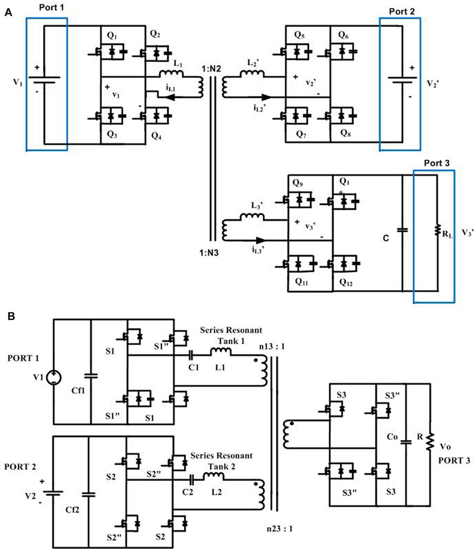
FIGURE 11. IMCs derived from full bridge. (A) A novel three-port converter derived from full-bridge Topology (Jiang et al., 2014). (B) A three-port full-bridge topology with two sries resonant tank (Krishnaswami and Mohan, 2009).
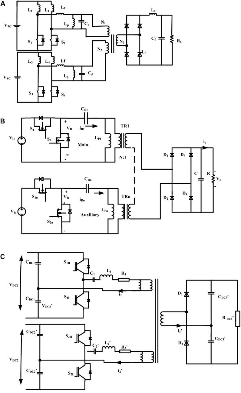
FIGURE 12. IMCs based on Half Bridge. (A) Topology of half-bridge current-fed multi-resonant bidirectional three-port converter (Samavatian et al., 2014). (B) Multi transformer connected new multiport CFL resonant converter (Asa et al., 2015). (C) Topology of a three-port resonant DC-DC converter working as DC transformer (Tran et al., 2019).
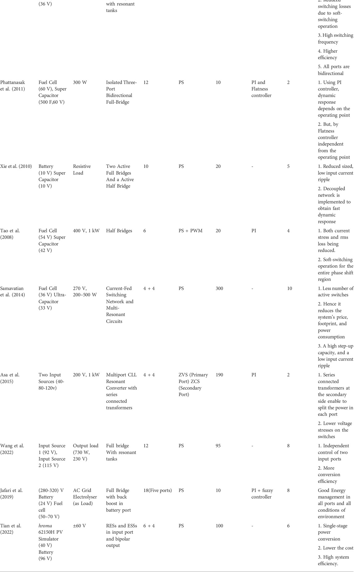
TABLE 3. Important features of reported isolated topologies.
4.4 Summary
The key objective of designing different configurations of MDCs is to solve the issues related to the instability of the renewable resources and the uncertainty of the power demand of the load. Even though there are several MDCs reported in the literature, they have diverse merits and demerits. The NIMC provide more cost-effective topologies as compared to the other two types since non-isolated converters use low power components with the minimum component count. Furthermore, the necessity to use a HFT may raise the price of the IMCs and PIMCs. Amongst the NIMC, the configurations with greater conversion ratio are more expensive than the others owing to the utilization of a coupled-coil. System consistency is a critical parameter to assess the effectiveness of the MDCs. The partially isolated and non-isolated MDCs are comparatively more reliable than the isolated MDCs since the reliability of the MDC decreases with an increase in component count. Even though all the studied MDCs can control the working of MPPT, and can meet the load requirement through the BSS, there are some restrictions to the implementation of the MDCs owing to their distinctive topology. The NIMC are the better choice for compact low-power systems, however not suitable for the systems that need strong insulation between ports, where PIMC and IMC are good candidates.
5 Conclusion
This paper presents a comprehensive evaluation of MDC setups for integrating SPV and BSS. The primary goal of developing MDC is to enable a single-stage energy transformation that primarily incorporates varied renewable resources while retaining their specific characteristics, such as MPPT for SPV generation and BSS charging/discharging capability. The proposed MDCs are mostly superior to the conventional dual-stage structure of SPV and BSS integration regarding size, cost of the converter, energy intensity, compactness, and performance of the MDC. As a result, future research will be focused on building nonisolated MPCs for a low-power system that provide higher performance in terms of system flexibility, such as battery charging from the grid and modularity. Since, both the PV and battery ports are bidirectional and can be utilised alternately. For partial as well as isolated topologies, the research focus will be on building MPCs with fewer devices and inventive design to enhance cost and efficiency.
Author contributions
All authors listed have made a substantial, direct, and intellectual contribution to the work and approved it for publication.
Acknowledgments
Authors are thankful to the management of Vellore Institute of Technology, VIT -Vellore. And this work is carried out in the lab of Digital Simulation Lab (DSL) from the School of Electrical Engineering (SELECT Electricity Access Keeps Climbing Globally), VIT-Vellore, Tamil Nādu, India.
Conflict of interest
The authors declare that the research was conducted in the absence of any commercial or financial relationships that could be construed as a potential conflict of interest.
Publisher’s note
All claims expressed in this article are solely those of the authors and do not necessarily represent those of their affiliated organizations, or those of the publisher, the editors and the reviewers. Any product that may be evaluated in this article, or claim that may be made by its manufacturer, is not guaranteed or endorsed by the publisher.
References
Alves, D. B. S., Praça, P. P., Oliveira, D. S., Barreto, L. H. S. C., and de Freitas, L. C. G. (2015). “A single-stage three-port boost converter with high voltage gain based on the bidirectional version of the three-state switching cell,” in Conference Proceedings - IEEE applied power electronics conference and exposition - APEC (Uberlndia, MG: Institute of Electrical and Electronics Engineers Inc.), 1934–1940. doi:10.1109/APEC.2015.7104611
Asa, E., Colak, K., Bojarski, M., and Czarkowski, D. (2015). Asymmetrical duty-cycle and phase-shift control of a novel multiport CLL resonant converter. IEEE J. Emerg. Sel. Top. Power Electron. 3, 1122–1131. doi:10.1109/JESTPE.2015.2408565
Balaji, C., Shekar Dash, S., Hari, N., and Chandra babu, P. (2017). “A four port non-isolated multi input single output DC-DC converter fed induction motor,” in 6th international conference on renewable energy research and applications, 5–8.
Bayat, P., and Baghramian, A. (2020). Partly isolated three-port DC-DC converter based on impedance network. IET Power Electron. 13, 2175–2193. doi:10.1049/iet-pel.2019.1348
Bhaskar, M. S., Ramachandaramurthy, V. K., Padmanaban, S., Blaabjerg, F., Ionel, D. M., Mitolo, M., et al. (2020). Survey of DC-DC non-isolated topologies for unidirectional power flow in fuel cell vehicles. IEEE Access 8, 178130–178166. doi:10.1109/ACCESS.2020.3027041
Chandrasekar, B., Nallaperumal, C., Padmanaban, S., Bhaskar, M. S., Holm-Nielsen, J. B., Leonowicz, Z., et al. (2020). Non-isolated high-gain triple port DC-DC buck-boost converter with positive output voltage for photovoltaic applications. IEEE Access 8, 113649–113666. doi:10.1109/ACCESS.2020.3003192
Charles Rajesh Kumar, J., and Majid, M. A. (2020). Renewable energy for sustainable development in India: Current status, future prospects, challenges, employment, and investment opportunities. Energy sustain. Soc. 10, 2. doi:10.1186/s13705-019-0232-1
Chen, Z. (2014). “Three-port ZVS converter with PWM plus secondary-side phase-shifted for photovoltaic-storage hybrid systems,” in Conference Proceedings - IEEE applied power electronics conference and exposition - APEC (Fort Worth, TX: Institute of Electrical and Electronics Engineers Inc.), 3066–3071. doi:10.1109/APEC.2014.6803742
Chen, Z., Wu, Q., Li, M., Xu, Y., and Wang, Q. (2015). “A three-port DC-DC converter with low frequency current ripple reduction technique,” in Conference Proceedings - IEEE applied power electronics conference and exposition - APEC (Charlotte, NC: Institute of Electrical and Electronics Engineers Inc.), 2069–2074. doi:10.1109/APEC.2015.7104634
Chien, L. J., Chen, C. C., Chen, J. F., and Hsieh, Y. P. (2014). Novel three-port converter with high-voltage gain. IEEE Trans. Power Electron. 29, 4693–4703. doi:10.1109/TPEL.2013.2285477
Ding, S., Wu, H., Xing, Y., Fang, Y., and Ma, X. (2013). “Topology and control of a family of non-isolated three-port DC-DC converters with a bidirectional cell,” in Conference Proceedings - IEEE applied power electronics conference and exposition - APEC, 1089–1094. doi:10.1109/APEC.2013.6520435
Duarte, J. L., Hendrix, M., and Simões, M. G. (2007). Three-port bidirectional converter for hybrid fuel cell systems. IEEE Trans. Power Electron. 22, 480–487. doi:10.1109/TPEL.2006.889928
Falcones, S., and Ayyanar, R. (2010). “Simple control design for a three-port DC-DC converter based PV system with energy storage,” in Conference Proceedings - IEEE applied power electronics conference and exposition - APEC, 2149–2153. doi:10.1109/APEC.2010.5433534
Faraji, R., DIng, L., Rahimi, T., Kheshti, M., and Islam, M. R. (2021). Soft-switched three-port DC-DC converter with simple auxiliary circuit. IEEE Access 9, 66738–66750. doi:10.1109/ACCESS.2021.3076183
Feldman, S. (2022). Chart: Electricity access keeps climbing globally | Statista. Available at: https://www.statista.com/chart/16552/electricity-access-worldwide/(Accessed May 16, 2022).
Hu, W., Wu, H., Xing, Y., and Sun, K. (2014). “A full-bridge three-port converter for renewable energy application,” in Conference Proceedings - IEEE applied power electronics conference and exposition - APEC (Fort Worth, TX: Institute of Electrical and Electronics Engineers Inc.), 57–62. doi:10.1109/APEC.2014.6803289
Hu, Y., Xiao, W., Cao, W., Ji, B., and Morrow, D. J. (2015). Three-port DC-DC converter for stand-alone photovoltaic systems. IEEE Trans. Power Electron. 30, 3068–3076. doi:10.1109/TPEL.2014.2331343
IEEE Power Electronics Society (2017). “Institute of electrical and electronics Engineers, and IEEE industry applications society,” in The 6th IEEE international conference on renewable energy research and applications (ICRERA 2017) (San Diego, CA, USA. 05-08 November 2017.
Ieee, and Ieee (2012). IEEE energy conversion congress and exposition. IEEE industry applications society, and Institute of electrical and electronics Engineers novel topology and control of a non-isolated three port DC-DC converter for PV-battery power system.
Jafari, M., Malekjamshidi, Z., Lu, D. D. C., and Zhu, J. (2019). Development of a fuzzy-logic-based energy management system for a multiport multioperation mode residential smart microgrid. IEEE Trans. Power Electron. 34, 3283–3301. doi:10.1109/TPEL.2018.2850852
Jiang, Y., Liu, F., Ruan, X., and Wang, L. (2014). “Optimal idling control strategy for three-port full-bridge converter,” in International power electronics conference, IPEC-hiroshima - ECCE asia 2014 (IEEE Computer Society), 458–464. doi:10.1109/IPEC.2014.6869623
Krishnaswami, H., and Mohan, N. (2009). Three-port series-resonant DC-DC converter to interface renewable energy sources with bidirectional load and energy storage ports. IEEE Trans. Power Electron. 24, 2289–2297. doi:10.1109/TPEL.2009.2022756
Madhana, R., and Mani, G. (2022). Power enhancement methods of renewable energy resources using multiport DC-DC converter: A technical review. Sustain. Comput. Inf. Syst. 35, 100689. doi:10.1016/j.suscom.2022.100689
McDonough, M. (2015). Integration of inductively coupled power transfer and hybrid energy storage system: A multiport power electronics interface for battery-powered electric vehicles. IEEE Trans. Power Electron. 30, 6423–6433. doi:10.1109/TPEL.2015.2422300
Mexis, I., and Todeschini, G. (2020). Battery energy storage systems in the United Kingdom: A review of current state-of-the-art and future applications. Energies (Basel) 13, 3616. doi:10.3390/en13143616
Mira, M. C., Zhang, Z., Knott, A., and Andersen, M. A. E. (2017). Analysis, design, modeling, and control of an interleaved-boost full-bridge three-port converter for hybrid renewable energy systems. IEEE Trans. Power Electron. 32, 1138–1155. doi:10.1109/TPEL.2016.2549015
Nakayama, H., and Hiraki, E. (2008). “Poznań stand-alone photovoltaic generation system with combined storage using lead battery and EDLC,” in International power electronics and motion control conference.13 09.01-03 Poznań, and EPE-PEMC 13 2008.09.01-03.
Nejabatkhah, F., Danyali, S., Hosseini, S. H., Sabahi, M., and Niapour, S. M. (2012). Modeling and control of a new three-input dc-dc boost converter for hybrid PV/FC/battery power system. IEEE Trans. Power Electron. 27, 2309–2324. doi:10.1109/TPEL.2011.2172465
Parthiban, R., and Rajambal, K. (2014). “Performance investigation of three-port converter for hybrid energy systems,” in Proceedings of the 2014 IEEE 2nd international conference on electrical energy systems, ICEES 2014 (Chennai, India: Institute of Electrical and Electronics Engineers Inc.), 261–266. doi:10.1109/ICEES.2014.6924178
Phattanasak, M., Gavagsaz-Ghoachani, R., Martin, J. P., Nahid-Mobarakeh, B., Pierfederici, S., and Davat, B. (2011). “Comparison of two nonlinear control strategies for a hybrid source system using an isolated three-port bidirectional DC-DC converter,” in 2011 IEEE vehicle power and propulsion conference (Chicago, IL: VPPC). doi:10.1109/VPPC.2011.6043161
Piris-Botalla, L., Oggier, G. G., Airabella, A. M., and García, G. O. (2014). Power losses evaluation of a bidirectional three-port DC-DC converter for hybrid electric system. Int. J. Electr. Power & Energy Syst. 58, 1–8. doi:10.1016/j.ijepes.2013.12.021
Qian, Z., Abdel-Rahman, O., Al-Atrash, H., and Batarseh, I. (2010). Modeling and control of three-port DC/DC converter interface for satellite applications. IEEE Trans. Power Electron. 25, 637–649. doi:10.1109/TPEL.2009.2033926
Qian, Z., Abdel-Rahman, O., Zhang, K., Hu, H., Shen, J., and Batarseh, I. (2011). “Design and analysis of three-port DC/DC converters for satellite platform power system,” in IEEE energy conversion congress and exposition: Energy conversion innovation for a clean energy future, ECCE 2011, Proceedings, 1454–1460. doi:10.1109/ECCE.2011.6063952
Qian, Z., Rahman, O. A., Reese, J., Atrash, H., and Batarseh, I. (2009). “Dynamic analysis of three-port DC/DC converter for space applications,” in Conference Proceedings - IEEE applied power electronics conference and exposition - APEC, 28–34. doi:10.1109/APEC.2009.4802628
Qin, X., Wu, H., Zhang, J., and Xing, Y. (2014). “PWM+SSPS-controlled full-bridge three-port converter for aerospace power system,” in IEEE transportation electrification conference and expo, ITEC asia-pacific 2014 - conference Proceedings (Beijing, China: Institute of Electrical and Electronics Engineers Inc.). doi:10.1109/ITEC-AP.2014.6940755
Rehman, Z., Al-Bahadly, I., and Mukhopadhyay, S. (2015). Multiinput DC-DC converters in renewable energy applications - an overview. Renew. Sustain. Energy Rev. 41, 521–539. doi:10.1016/j.rser.2014.08.033
Riffonneau, Y., Bacha, S., Barruel, F., and Ploix, S. (2011). Optimal power flow management for grid connected PV systems with batteries. IEEE Trans. Sustain. Energy 2, 309–320. doi:10.1109/TSTE.2011.2114901
Samavatian, V., Bathaee, S. M. T., and Fereidunian, A. (2014). “Half-bridge current-fed multi-resonant bidirectional three-port DCDC converter for flexible distributed generations,” in Pedstc 2014 - 5th annual international power electronics, drive systems and technologies conference (IEEE Computer Society), 172–176. doi:10.1109/PEDSTC.2014.6799365
Shaqsi, A. Z., Sopian, K., and Al-Hinai, A. (2020). Review of energy storage services, applications, limitations, and benefits. Energy Rep. 6, 288–306. doi:10.1016/j.egyr.2020.07.028
Subramanian, A., and Santha, K. R. (2020). Review of multiport isolated bidirectional converter interfacing renewable and energy storage systems. Int. J. Power Electron. Drive Syst. (IJPEDS) 11, 466–476. doi:10.11591/ijpeds.v11.i1.pp466-476
Sun, X., Liu, F., Xiong, L., and Wang, B. (2014a). “Research on dual Buck/Boost integrated three-port bidirectional DC/DC converter,” in IEEE transportation electrification conference and expo, ITEC asia-pacific 2014 - conference Proceedings (Beijing, China: Institute of Electrical and Electronics Engineers Inc.). doi:10.1109/ITEC-AP.2014.6941114
Sun, X., Shen, Y., and Li, W. (2014b). “A novel LLC integrated three-port DC-DC converter for stand-alone PV/battery system,” in IEEE transportation electrification conference and expo, ITEC asia-pacific 2014 - conference Proceedings (Beijing, China: Institute of Electrical and Electronics Engineers Inc.). doi:10.1109/ITEC-AP.2014.6941090
Suresh, K., Bharatiraja, C., Chellammal, N., Tariq, M., Chakrabortty, R. K., Ryan, M. J., et al. (2021). A multifunctional non-isolated dual input-dual output converter for electric vehicle applications. IEEE Access 9, 64445–64460. doi:10.1109/ACCESS.2021.3074581
Tao, H., Duarte, J. L., and Hendrix, M. A. M. (2008). Three-port triple-half-bridge bidirectional converter with zero-voltage switching. IEEE Trans. Power Electron. 23, 782–792. doi:10.1109/TPEL.2007.915023
Tian, Q., Zhou, G., Li, H., Yang, Y., and Zhou, D. (2022). Symmetrical bipolar output isolated four-port converters based on center-tapped winding for bipolar DC bus applications. IEEE Trans. Power Electron. 37, 1–2351. doi:10.1109/TPEL.2021.3107154
Tran, Y.-K., Freijedo, F. D., and Dujic, D. (2019). Open-loop power sharing characteristic of a three-port resonant LLC converter. CPSS Trans. Power Electron. Appl. 4, 171–179. doi:10.24295/CPSSTPEA.2019.00017
Vettuparambil, A., Chatterjee, K., and Fernandes, B. G. (2022). Dual-active-bridge-based multiport converter with Split DC links. IEEE Trans. Ind. Electron. 69, 485–494. doi:10.1109/TIE.2021.3051576
Wang, C., and Nehrir, M. H. (2008). Power management of a stand-alone wind/photovoltaic/fuel cell energy system. IEEE Trans. Energy Convers. 23, 957–967. doi:10.1109/TEC.2007.914200
Wang, J., Sun, K., Xue, C., Liu, T., and Li, Y. (2022). Multi-port DC-AC converter with differential power processing DC-DC converter and flexible power control for battery ESS integrated PV systems. IEEE Trans. Ind. Electron. 69, 4879–4889. doi:10.1109/TIE.2021.3080198
Wang, Z., and Li, H. (2013). An integrated three-port bidirectional DC-DC converter for PV application on a DC distribution system. IEEE Trans. Power Electron. 28, 4612–4624. doi:10.1109/TPEL.2012.2236580
Wu, H., Chen, R., Zhang, J., Xing, Y., Hu, H., and Ge, H. (2011a). A family of three-port half-bridge converters for a stand-alone renewable power system. IEEE Trans. Power Electron. 26, 2697–2706. doi:10.1109/TPEL.2011.2125991
Wu, H., Sun, K., Chen, R., Hu, H., and Xing, Y. (2012). Full-bridge three-port converters with wide input voltage range for renewable power systems. IEEE Trans. Power Electron. 27, 3965–3974. doi:10.1109/TPEL.2012.2188105
Wu, H., Sun, K., Ding, S., and Xing, Y. (2013). Topology derivation of nonisolated three-port DC-DC converters from DIC and DOC. IEEE Trans. Power Electron. 28, 3297–3307. doi:10.1109/TPEL.2012.2221746
Wu, H., Xing, Y., Chen, R., Zhang, J., Sun, K., and Ge, H. (2011b). “A three-port half-bridge converter with synchronous rectification for renewable energy application,” in IEEE energy conversion congress and exposition: Energy conversion innovation for a clean energy FutureProceedings (Phoenix, AZ: ECCE), 3343–3349. doi:10.1109/ECCE.2011.6064220
Wu, H., Xing, Y., Xia, Y., and Sun, K. (2011c). “A family of non-isolated three-port converters for stand-alone renewable power system,” in IECON Proceedings (industrial electronics conference), 1030–1035. doi:10.1109/IECON.2011.6119337
Xie, J., Zhang, X., Zhang, C. W., and Liu, S. Y. (2010). “A novel three-port bi-directional DC-DC converter,” in 2nd international symposium on power electronics for distributed generation systems (Hefei, China: PEDG), 717–720. doi:10.1109/PEDG.2010.5545784
Zhang, J., Wu, H., Cao, F., Xing, Y., and Ma, X. (2014). “Analysis and design of DC distributed DC power system with modular three-port converter,” in IEEE international symposium on industrial electronics (Istanbul, Turkey: Institute of Electrical and Electronics Engineers Inc.), 416–421. doi:10.1109/ISIE.2014.6864649
Zhang, P., Chen, Y., Lu, Z., and Kang, Y. (2015). “The cost-efficient, common-ground, non-isolated three-port converter deduced from the single-inductor dual-output (SIDO) topology,” in Conference Proceedings - IEEE applied power electronics conference and exposition - APEC (Charlotte, NC: Institute of Electrical and Electronics Engineers Inc.), 2020–2025. doi:10.1109/APEC.2015.7104626
Zhou, Z., Wu, H., Ma, X., and Xing, Y. (2012). “A non-isolated three-port converter for stand-alone renewable power system,” in IECON Proceedings (industrial electronics conference), 3352–3357. doi:10.1109/IECON.2012.6389360
Zhu, H., Zhang, D., Athab, H. S., Wu, B., and Gu, Y. (2015a). PV isolated three-port converter and energy-balancing control method for PV-battery power supply applications. IEEE Trans. Ind. Electron. 62, 1–3606. doi:10.1109/TIE.2014.2378752
Zhu, H., Zhang, D., Zhang, B., and Zhou, Z. (2015b). A nonisolated three-port DC-DC converter and three-domain control method for PV-battery power systems. IEEE Trans. Ind. Electron. 62, 4937–4947. doi:10.1109/TIE.2015.2393831
Nomenclature
Abbreviations
AOS Ability of Source
BSS Battery Storage System
DAB Dual Active Bridge
DDC DC/DC converter
DIDO Double Input Double-Output
DPPC Differential Power Processing DC-DC Converter
ESS Energy Storage Systems
FB-TPC Full-Bridge TPC
HFT High-Frequency Transformer
IEA International Energy Agency
IMC Isolated MDC
MDC Multiport DC/DC converter
MPC Multi-Port DC-AC converter
NIMC Non-Isolated MDC
PIMC Partially Isolated MDC
PWM + SSPS PWM with Secondary-Side Phase-Shift-Controlled
PWM Pulse Width Modulated
RES Renewable Energy Systems
SISO Single-Input-Single-Output
SDC Step-Down Converter
SPV Solar Photovoltaic
SOC State of Charge
TISO triple-input-single-output
TPC Three-Port Converter
Keywords: isolated converters, multiport converters, non-isolated converters, partially-isolated converters, renewable energy, solar PV, battery storage system
Citation: Shanmugam S and Sharmila A (2022) Multiport converters for incorporating solar photovoltaic system with battery storage: A pilot survey towards modern influences, challenges and future scenarios. Front. Energy Res. 10:947424. doi: 10.3389/fenrg.2022.947424
Received: 18 May 2022; Accepted: 29 August 2022;
Published: 07 October 2022.
Edited by:
Salah Kamel, Aswan University, EgyptReviewed by:
Subhasis Roy, University of Calcutta, IndiaArsalan Muhammad Soomar, Gdansk University of Technology, Poland
Suprava Chakraborty, Vellore Institute of Technology (VIT), India
Copyright © 2022 Shanmugam and Sharmila. This is an open-access article distributed under the terms of the Creative Commons Attribution License (CC BY). The use, distribution or reproduction in other forums is permitted, provided the original author(s) and the copyright owner(s) are credited and that the original publication in this journal is cited, in accordance with accepted academic practice. No use, distribution or reproduction is permitted which does not comply with these terms.
*Correspondence: A. Sharmila, ZHJhc2hhcm1pbGEyMDE5QGdtYWlsLmNvbQ==