 Yu Zhou1*
 Chen Chen
95% of researchers rate our articles as excellent or good
Learn more about the work of our research integrity team to safeguard the quality of each article we publish.
Find out more
ORIGINAL RESEARCH article
Front. Energy Res. , 30 August 2022
Sec. Electrochemical Energy Storage
Volume 10 - 2022 | https://doi.org/10.3389/fenrg.2022.945132
This article is part of the Research Topic Artificial Intelligence Applications in Low Carbon Renewable Energy and Energy Storage Systems, Volume II View all 4 articles
Virtual synchronous generators (VSG) are widely applied in microgrid technology due to their ability to withstand the impact of grid-connected inverters without inertia. The frequency deviation in the droop control of VSG has a reducing effect on the hosting capacity of the microgrid. Therefore, this article proposes a VSG-based frequency deviation-free control strategy. When the microgrid is in the island/grid connected switching operation mode, it will result in violent fluctuations of the active power on the condition that there is a reactive and fast power change. Therefore, the delay characteristic of a synchronous generator is introduced into VSG to achieve a smooth transition of reactive power and steady-state value that lowers the impact on the system. The rotational inertia is a fixed value, which may fail to meet certain control requirements of the microgrid, such as suppressing power oscillation and rapidly recovering frequency. The fixed moment of inertia is later on improved to an adaptive inertia moment that can effectively solve the problem of rapid rise and fall of frequency as well as improve the frequency response of the microgrid. Finally, the simulation model is established by MATLAB to verify the effectiveness and feasibility of the proposed control algorithm.
In recent years, the distributed generation (DG) has been gradually increasing its involvement in the distribution network (Kumar and Bhimasingu, 2015; Hu et al., 2021). This has not only introduced new opportunities, but has also resulted in more challenges (Zhu et al., 2018; Wang et al., 2021). On one hand, distributed energy, which is as a new power supply, transforms the distribution network from passive to active. On the other hand, the grid-connected inverter has a fast response speed, which, to some extent, has no inertial. This property is not favorable and does not guarantee the safety of the microgrid operations (Pogaku et al., 2007; Nikolovski et al., 2019; Shi and Zhao, 2022). An insufficient or poor quality power supply in the distribution of the microgrid network limits the use of the kinetic energy of the rotor to exchange energy with the power grid, similar to what the synchronous generator does. An amalgamation of the traditional power system operation and the grid-connected inverter produces similar external characteristics of the synchronous generator. The DG can recognize friendly access to improve on the stability of the grid system. Using VSG technology, the grid-connected inverter generates similar rotor inertia as that of the synchronous generator. VSG is useful for a smooth switching between the island- and grid-connected modes (Zhang et al., 2021).
In Zhong and Weiss (2011), the basic principles of VSG that include stability, operation control strategy, key problems, and research status of VSG technology are summarized. Lv et al. (2014) proposed an adaptive control strategy of the VSG moment of inertia and damping coefficient to improve the frequency response. However, the inverter in this strategy is equivalent to a current source, thereby making it unsuitable for the islanded microgrid. Shi et al. (2017) focused on the problem of power output limitation that is as a result of the traditional VSG control. This study proposed a VSG power control strategy based on adaptive mode switching that can achieve the real-time tracking of voltage and current. Shi et al. (2016) proposed the switching operation control strategy based on the VSG microgrid island/grid-connected mode. In Zhang and Li (2015), the VSG technique enabled the inverter to emulate the inertia of a synchronous generator, but that did not solve the problem of frequency deviation.
In summary, the existing research has made some progress, but there are still many problems that need to be addressed. When the microgrid is in the island/grid-connected switching operation mode, and there is a reactive and fast power change, it will affect the active power and cause violent fluctuations. When the microgrid is in the grid connected/island switching operation mode, the droop control of VSG cannot avoid frequency deviation, which in turn reduces the microgrid’s load capacity. The rotational inertia normally has a fixed value that cannot be changed or modified to meet some control requirements such as, suppressing power oscillation and rapidly recovering frequency of the microgrid.
In order to solve the aforementioned problems, based on Xu et al. (2017), this article proposes a VSG-based frequency deviation-free control strategy, which can effectively reduce the fluctuations caused by the rapid change of reactive power during the grid-connected/island switching of the microgrid. In addition, the proposed strategy can also improve the frequency response capability of the microgrid and eliminate the frequency adjustment process in pre-synchronization. The main works of this article are as follows:
The frequency proportional–integral (PI) module feedback is used to replace the traditional damping module to solve the problem of frequency deviation.
An additional first-order delay module is applied to achieve a smooth transition of reactive power to a new steady state and reduce its impact on the system.
The moment of inertia is changed to an adaptive value that is dynamically adjusted in real time based on the frequency deviation caused by the load disturbance, which can effectively solve the problem of the rapid rise and fall of frequency.
The remainder of this article is organized as follows. Section 2 introduces the basic principle of VSG. Section 3 establishes the model of an adaptive inertia microgrid smooth switching control strategy. The simulation results are shown in Section 4. Conclusions are collected in Section 5.
The simulation of the working principle of the synchronous generator produces VSG, making the grid inverter get similar running characteristics. The topological graph of VSG is shown in Figure 1.
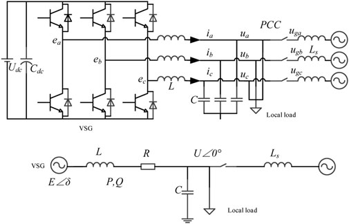
FIGURE 1. The topological graph of VSG.
The motion equation of the VSG rotor is (Zhou et al., 2006):
where J represents the virtual inertial, and Tm, Te are the virtual mechanical torque and electromagnetic torque, separately. Pm and Pe respectively show the mechanical power and the electromagnetic power. D is the constant damping coefficient. ω is the rotor angular velocity, namely the electrical angular velocity. ω0 is the grid synchronous angular velocity. φ is the power angle. In the existence of J, the grid-connected inverter has inertia in the dynamic power and frequency processes. The grid-connected power generation device has the ability to damp the grid power oscillation due to the existence of D.
The VSG mechanical power equation is given as (Zhou et al., 2006):
where Pref represents the active power reference and Kω is the adjustment coefficient. According to Eq. 2, the droop characteristics exist between the active power and the frequency, and VSG has the characteristics of self-synchronization of a conventional generator.
The active frequency control equation of inverter is (Meng et al., 2014):
where J0 is the initial value of the moment of inertia of VSG into the microgrid. ωref is the reference angle frequency. ωg is the common bus angle frequency. Pref is the reference active power. Pavg is the first-order filtered average active power. Dp is the frequency droop coefficient. Kp and Ki are the proportional integral coefficients.
The control block diagram for frequency deviation-free active power–frequency is shown in Figure 2.

FIGURE 2. Active power control block diagram.
When
Figure 2 shows the transfer function between ∆ω and ∆P as (Shi et al., 2016):
The initial value theorem of the unit power step excitation:
The final value theorem of the unit power step excitation:
By Eqs 4–6, it is the second order transfer function relationship between ∆ω and ∆P, and the unit-step excitation power
In conclusion, the frequency deviation-free control strategy is applied in the steady state while the controller model is the same for both the grid- connected and island modes, which are conducive to multi-mode controls.
The reactive power–voltage control of VSG is utilized to emulate the excitation–regulation function of a synchronous generator that is used to recognize the droop characteristics of reactive power and voltage amplitude. This control plays vital roles in the grid-connected operation mode and in the island mode. In grid-connected mode, the control transmits the specified reactive power to the power grid, while in the island mode, it controls the output voltage of the inverter where the load determines the output reactive power.
The reference voltage of the distributed inverter is expressed as:
where Dq is the droop coefficient of reactive power. T is the time constant of the delay module. kq, kn are the proportional integral coefficients. Qref is the reference value for reactive power. Qavg is the reactive power output by the VSG. E is the output signal of the reactive power controller. Eset is the distributed inverter supply voltage reference. The reactive power control block diagram is shown in Figure 3.
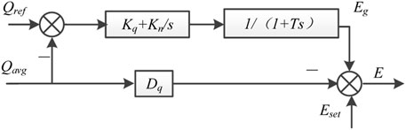
FIGURE 3. Reactive power control block diagram.
When the island/grid-connected switching operation is performed, the PI controller is used to control the reactive power output causing a high response speed. In a real scenario of synchronous generators, the reactive power takes longer to transition to a new steady state. When there is a high rate of change, the active power will be affected and a sharp fluctuation will occur. Therefore, an additional first-order delay module is applied here to achieve a smooth transition of reactive power to a new steady state and reduce its impact on the system.
In the re-production of the characteristics of a synchronous generator, the double-loop controller is needed to increase the power grid quality as well as tracking a timely and accurate upper VSG controller. This study chooses the LC filter current as the inner loop feedback signal, where the capacitance current and the output voltage are adaptive due to the differential capacitive current. Also, the inner current loop improves the load inverter capacity. The block diagram of the voltage and current double loop control is illustrated in Figure 4; (Zhang and Li, 2015).where U*odq is input voltage signal, i is the input current of the inner loop, k is the gain coefficient, kp represents the inverter transfer function, and U0 is the output voltage of the inverter. C and L are filter capacitance and inductance, respectively. ic and iL are the currents of the capacitor and inductor separately. iabc is the bus current microgrid and Uodq represents the output voltage signal.
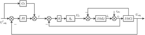
FIGURE 4. Voltage current double loop control block diagram.
A synchronous generator has a large rotational inertia and it is capable of storing a large amount of rotor kinetic energy. When the grid connected, the microgrid is required to have a higher damping in order to restrain the power oscillation. When the power grid is disturbed, the kinetic energy is stored in the rotor for giving support and maintaining a stable operation in the power grid. When the disturbance settles, the frequency is finally restored (Yang et al., 2016). Generally, the VSG control is only a fixed rotational inertia control, hence, it cannot simultaneously meet the aforementioned three requirements causing limitations.
This study has used rotational inertia to control the inertia. In the switching process, the moment of inertia is set to a smaller value, which does not cause power oscillations. The moment of inertia is then changed to an adaptive moment of inertia that is dynamically adjusted in real time based on the frequency deviation caused by the load disturbance. This shows that the change can effectively solve the problem of the rapid rise and fall of frequency, which is beneficial to the improvement of the microgrid’s frequency response. Adaptive rotation control type is expressed as:
where kf is the frequency tracking coefficient and klim is the frequency of change limited value.
The adaptive rotational inertia control block diagram is shown in Figure 5.
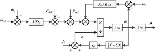
FIGURE 5. Adaptive rotational inertia control block diagram.
The inertia time constant ζ and the active frequency droop coefficient Mp are respectively expressed as follows:
From the equations, it can be shown that the adaptive inertia control has an influence on ζ and has no effect on Mp. Simply put, the adaptive rotational inertia control can effectively decrease the frequency rate without frequency change.
For different operating modes, the control principle of the microgrid switching based on VSG control operates in three steps. Firstly, the switching between the grid-connected mode and the island mode is controlled by VSG, and J takes smaller values to achieve stable power. Secondly, when the local load disturbance exceeds the set value, it then causes frequency deviation, thereby switching the VSG control to adaptive control. This will increase the value of J and reduce the frequency speed, thus solving the problem of high frequency change during the traditional VSG control. Finally, after the load disturbance is complete, the frequency is then restored to a steady state, and the adaptive control is switched to VSG control again.
VSG can still maintain the potential while both in the planned and unplanned island modes under the condition where the grid power connection is removed. A successful smooth transition from the grid connected mode to the island mode is then achieved.
When the VSG is running on the island mode, due to the effects of voltage and frequency adjustments, there exists a certain deviation of voltage amplitude and frequency between the microgrid and the power grid. If the microgrid from the island mode is switched to the grid-connected mode directly at this point, there will be a large current shock which may lead to a failure in switching.
Selecting C phase as an example; uvc is terminal voltage of VSG in the island mode, ugc represents power grid voltage, Uv is the voltage amplitude of the microgrid in the island mode, and Ug is the power grid voltage amplitude.
Usually, the voltage amplitude differences are not huge between a microgrid with island mode and a power grid. This can approximately be
It is shown that the frequency, phase, and amplitude deviations exist between the microgrid voltage and the power grid voltage, while the instantaneous voltage deviation between the points of couple connection can be up to 2U. Therefore, before the inverter switching, the inverter output voltage amplitude, phase, and frequency are equal to those of the power grid. Otherwise, there will be a greater impact current and voltage in the power grid leading to island/grid-connected switching failure. The control algorithm that is proposed in this article can avoid the steady state frequency deviation, thus the frequency adjustment process in the process of pre-synchronization can be eliminated.
In this article, the MATLAB/Simulink was used to simulate the proposed VSG control strategy. The simulation results are presented to demonstrate the effectiveness and feasibility of the proposed control strategy. In the simulation, the system parameters are designed as: microgrid-side bus voltage of 60 V, power grid-side bus voltage of 380 V, 100 kW active power of the load 1, 10 kVAR reactive power of the load 1, 7 kW active power of the load 2, 1 kVar reactive power of the load 2, 2500 W active power of the load 3, and 1,000 VAR of reactive power of the load 3. DC inverter source voltage of 120 V, rated active power of 5,000 W, and rated reactive power of 1,500 VAR were also set.
The figures illustrate the simulation results that MATLAB/Simulink processed after the experiment was carried out. Figure 6A illustrates the simulation result for VSG-based microgrid smooth switching control. Figure 6B illustrates the VSG-based simulation result for frequency deviation-free control of the microgrid’s smooth switching control. Moreover, Figure 6C illustrates the simulation result for VSG-based reactive delay smooth switching control for the microgrid. Finally, Figure 6D illustrates the simulation results for VSG-based adaptive inertial integrated control for the microgrid.
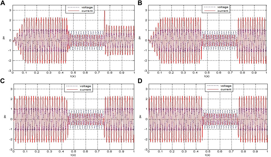
FIGURE 6. Integrated control chart of microgrid smooth switching. (A)VSG-based microgrid smooth switching control; (B)VSG-based frequency deviation-free control; (C)VSG-based reactive delay smooth switching control; and (D)VSG-based adaptive inertial integrated control.
During the analysis, the study showed that, the microgrid operates in the island mode between times 0–0.45 s. The DC source used VSG-based frequency deviation-free control between times 0–0.3 s. Also, the pre-synchronization controller received the grid connected signal and started its operation between times 0.3–0.45 s. The switch is then closed at time 0.45 s when the microgrid recognizes island/grid-connected switching operation control and the PQ now controls the DC source. At 0.7 s, the microgrid is off the power grid while the DC source is still at the previous state where the PQ controls it. At time 0.75 s, the microgrid recognizes the grid connected/island switching operation control as the DC inverter is still switched into the VSG.
At times between 0 and 0.1 s, there is a small process of VSG-based microgrid control as illustrated in Figure 6A. At the switching period between time 0.45 and 0.75 s, there is a substantial oscillation which gradually decreases after a time of 0.75 s. Figure 6B illustrates that the VSG-based microgrid control still has a short start-up process at time between 0 and 0.1 s. During the switching process at the time of 0.45 s, there is a substantial oscillation, but the current remains stable after a time of 0.75 s. Figure 6C illustrates that the microgrid that is based on VSG control, can swiftly complete the response, but still leaves minimal fluctuations, while the switching process and the state after switching remains relatively stable. Figure 6D illustrates that the microgrid that is based on VSG is not only able to respond and fluctuate fast, but also achieve a smooth switching in the handover process as the current and voltage remain at a stable value.
Through the aforementioned analysis, it can be seen that the VSG-based adaptive inertia integrated control can not only quickly complete the response between 0 and 0.1 s, but also suppress the fluctuation well at 0.45 and 0.75 s when the microgrid operation mode is switching.
Figures 7–9 are the active output map, the reactive output map, and the frequency variation map of the corresponding control, respectively. In the following analysis, we use “A curve” to represent the traditional VSG control system, “B curve” to represent frequency deviation-free control system, “C curve” to represent the reactive power delay control system, and “D curve” to represent the adaptive integrated control system.
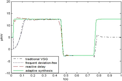
FIGURE 7. Active output of the microgrid.
In Figure 7, at 0.3 s, the pre-synchronous controller starts to work. The A curve and the B curve indicate that the active output of the DC source requires a certain time of buffering. The active outputs of the C curve and the D curve hardly require buffering time, but there is a small fluctuation in the C curve. In the 0.45 s island/grid connection switching operation, the control strategy of the microgrid and the power grid is switched. The active outputs of the A curve, the B curve, and the C curve fluctuate respectively but the D curve’s active output have a smooth transition. In 0.75 s, the active output phase of the A curve is obviously small compared to the previous one before switching, while the active outputs of the B curve, the C curve, and the D curve remain unchanged.
Figure 8 shows that, when the microgrid operation mode is switched at 0.45 and 0.75 s, there is a fast reactive power change which will affect the system and cause violent fluctuations. So, the A curve, the B curve, and the C curve significantly fluctuate. But, in the adaptive integrated control system, reactive power can smoothly transit to a new steady state and reduce its impact on the system by applying the first-order delay module. So, the D curve shows minimal fluctuation that maintains the stable operation of the microgrid. The proposed control strategy’s effectiveness is further verified.
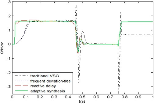
FIGURE 8. Reactive power output of the microgrid.
Figure 9 shows, in the whole process, the frequency variation of the microgrid. As shown in the A curve, when the microgrid operation mode is switched at 0.45 and 0.75 s, there exists a problem of the rapid rise and fall down of frequency due to the active power–frequency droop characteristics of a traditional VSG control. In the frequency deviation-free control system and the adaptive integrated control system, the moment of inertia is improved to an adaptive value which is dynamically adjusted based on the frequency deviation; this is beneficial to improve the microgrid’s frequency response. So, it can be seen that the D curve and the B curve are within the range of ±1 Hz, which is consistent with the frequency change index of a low power microgrid, and the D curve fluctuation is small and stable. During the completion of the task of the pre-synchronous controller, the voltage of the bus side of the microgrid can be tracked to the bus side voltage of the large power grid, and the conditions of the grid connection are completed.
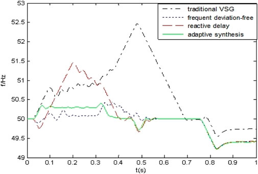
FIGURE 9. Frequency variation of the microgrid.
This article focused on the problem of frequency deviation of VSG’s active control algorithm in grid connection/island switching operation by proposing a frequency deviation-free active power–frequency droop control algorithm. At the same time, the fixed rotation inertia value is improved to the adaptive rotational inertia value. Compared with the traditional VSG active power droop control algorithm, the proposed approach has four obvious advantages which include: First, the PI module that replaced the traditional damping module can solve the problem of frequency deviation. Second, the grid-connected mode and the island mode are controlled by the same active power–frequency controller, which does not need to change the operating mode of the controller, thus being helpful to realize the multi-mode operation and smooth switching. Third, the increase of the first-order delay link can make the reactive power transition to the new steady state and reduce the impact on the system. Fourth, the real time dynamically adjusted adaptive moment of inertia value can effectively solve the problem of the rapid rise and fall of frequency, which is beneficial to improve the frequency response. The simulation results show that the microgrid has no large transient oscillation in the island mode, grid connected and mode switching. It is able to recognize the multi-mode operation and smooth switching of the microgrid. Lastly, the effectiveness and feasibility of the proposed algorithm are verified through simulations.
The original contributions presented in the study are included in the article/supplementary material; further inquiries can be directed to the corresponding author.
All the authors made contributions to the concept and design of the article; YZ is the main author of this work; CC and CO provided good advice and technical guidance for the manuscript; ML and JZ reviewed and edited the manuscript. All authors have read and agreed to the published version of the manuscript.
This research was funded by the National Key Research and Development Program of China under Grant No. 2021YFB2401303.
YZ was employed by Marketing Service Center, State Grid Jiangsu Electric Power Co., Ltd. CC, CO, ML, and JZ was employed by NARI Technology Co., Ltd.
All claims expressed in this article are solely those of the authors and do not necessarily represent those of their affiliated organizations, or those of the publisher, the editors, and the reviewers. Any product that may be evaluated in this article, or claim that may be made by its manufacturer, is not guaranteed or endorsed by the publisher.
Hu, J., Liu, X., Shahidehpour, M., and Xia, S. (2021). Optimal Operation of Energy Hubs With Large-Scale Distributed Energy Resources for Distribution Network Congestion Management. IEEE Trans. Sustain. Energy 12, 1755–1765. doi:10.1109/TSTE.2021.3064375
Lv, Z., Sheng, W., Zhong, Q., Liu, H., Zeng, Z., Yang, L., et al. (2014). Virtual Synchronous Generator and its Application in Microgrid. Proc. CSEE 34, 2591–2603. doi:10.13334/j.0258-8013.pcsee.2014.16.009
Meng, J., Wang, Y., Shi, X. C., Fu, C., and Li, P. (2014). Control Strategy and Parameter Analysis of Distributed Inverter Based on Virtual Synchronous Generator. Proc. Electrotech. Soc. 29, 1–10. doi:10.19595/j.cnki.1000-6753.tces.2014.12.001
Nikolovski, S., Baghaee, H. R., and Mlakic, D. (2019). Islanding Detection of Synchronous Generator-Based DGs Using Rate of Change of Reactive Power. IEEE Syst. J. 13, 4344–4354. doi:10.1109/jsyst.2018.2889981
Pavan Kumar, Y. V., and Bhimasingu, R. (2015). Renewable Energy Based Microgrid System Sizing and Energy Management for Green Buildings. J. Mod. Power Syst. Clean. Energy 3, 1–13. doi:10.1007/s40565-015-0101-7
Pogaku, N., Prodanovic, M., and Green, T. C. (2007). Modeling, Analysis and Testing of Autonomous Operation of an Inverter-Based Microgrid. IEEE Trans. Power Electron. 22, 613–625. doi:10.1109/TPEL.2006.890003
Shi, C., and Zhao, J. (2022). Passivity Enhancement Strategy of Grid-Connected Inverter System Based on the Adaptive Active Damper. Front. Energy Res. 10, 878450. doi:10.3389/fenrg.2022.878450
Shi, R., Zhang, X., Xu, H., Liu, F., and Cao, W. (2017). Power Control Strategy of Virtual Synchronous Generator Based on Adaptive Mode Switching. Trans. China Electrotech. Soc. 32, 127–137. doi:10.19595/j.cnki.1000-6753.tces.2017.12.013
Shi, R., Zhang, X., Xu, H., Liu, F., and Hu, C. (2016). Seamless Switching Control Strategy of Microgrid Operation Mode Based on Virtual Synchronous Generator. Autom. Electr. Power. Syst. 40, 16–23. doi:10.7500/AEPS20150615012
Wang, T., Rong, C., Tang, S., and Hong, Y. (2021). Stability Analysis for Distributed Secondary Control with Consideration of Diverse Input and Communication Delays for Distributed Generations in a DC Integrated Energy System. Front. Energy Res. 8, 633334. doi:10.3389/fenrg.2020.633334
Xu, Y., Zhang, T., and Yue, D. (2017). “Frequent Deviation-free Control for Micro-grid Operation Modes Switching Based on Virtual Synchronous Generator,” in International Conference on Life System Modeling and Simulation, LSMS 2017 and International Conference on Intelligent Computing for Sustainable Energy and Environment, Nanjing, China, September 22-24, 2017 (ICSEE 2017), 597–606. doi:10.1007/978-981-10-6364-0_60
Yang, J., Liu, Y., Pan, H., and Tang, J. (2016). Method of Frequent Deviation-free Control of Microgrid Inverter Based on Virtual Synchronous Generator Control. Power Syst. Technol. 41, 17–24. doi:10.13335/j.1000-3673.pst.2016.07.011
Zhang, T., and Li, X. (2015). A Control Strategy for Smooth Switching between Island Operation Mode and Grid-Connection Operation Mode of Microgrid Containing Photovoltaic Generations. Power Syst. Technol. 39, 904–910. doi:10.13335/j.1000-3673.pst.2015.04.005
Zhang, Z., Wu, J., Zheng, L., Xie, D., and Tang, X. (2021). An Inductor Current Sensorless Control Strategy Based on Modified VSG Method for Single-phase Microgrid Application With Seamless Transfer Capability. Front. Energy Res. 9, 752422. doi:10.3389/fenrg.2021.752422
Zhong, Q., and Weiss, G. (2011). Synchronverters: Inverters that Mimic Synchronous Generators. IEEE Trans. Ind. Electron 58, 1259–1267. doi:10.1109/TIE.2010.2048839
Zhou, W., Wu, Z., Tang, J., and Liu, D. (2006). The Equivalent Algorithm of SVPWM and the Essential Relationship between SVPWM and SPWM. Proc. CSEE 26, 133–137. doi:10.3321/j.issn:0258-8013.2006.02.024
Zhu, S., Wang, F., Guo, H., Wang, Q., and Gao, Y. (2018). Overview of Research on Droop Control Technology of DC Microgrid. Proc. CSEE 38, 1–10. doi:10.13334/j.0258-8013.pcsee.171408
C the filter capacitance
D the constant damping coefficient
Dp the frequency droop coefficient
Dq the droop coefficient of reactive power
E the output signal of the reactive power controller
Eset the distributed inverter supply voltage reference
i the input current of the inner loop
iabc the bus current
ic the currents of the capacitor
iL the currents of the inductor
J the virtual inertial
J0 the initial value of the inertia of VSG
k the gain coefficient
kf the frequency tracking coefficient
Ki the integral coefficient
klim the frequency of the change limited value
kn the integral coefficient
kp the inverter transfer function
Kp the proportional coefficient
kq the proportional coefficient
Kω the adjustment coefficient
L the filter inductance
Mp the active frequency droop coefficient
Pavg the first-order filtered average active power
Pe the electromagnetic power
Pm the mechanical power
Pref the active power reference
Qavg the reactive power output by VSG
Qref the reference value for reactive power
T the time constant of the delay module
Te the virtual electromagnetic torque
Tm the virtual mechanical torque
U*odq the input voltage signal
U0 the output voltage of the inverter
uc the terminal voltage of VSG in the island mode
Ug the power grid voltage amplitude
ugc the power grid voltage
Uodq the output voltage signal
Uv the voltage amplitude of the microgrid in the island mode
ζ the inertia time constant
φ the power angle
ω the rotor angular velocity
ω0 the grid synchronous angular velocity
ωg the common bus angle frequency
ωref the reference angle frequency
Keywords: microgrid, virtual synchronous generator, frequency deviation-free control, delay characteristic, adaptive inertia
Citation: Zhou Y, Chen C, Ou C, Liu M and Zhao J (2022) Frequency Deviation-Free Compound Control Strategy for Seamless Mode Transfer in Microgrids Based on VSG. Front. Energy Res. 10:945132. doi: 10.3389/fenrg.2022.945132
Received: 16 May 2022; Accepted: 21 June 2022;
Published: 30 August 2022.
Edited by:
Zhile Yang, Shenzhen Institutes of Advanced Technology (CAS), ChinaReviewed by:
Yizhen Wang, Tianjin University, ChinaCopyright © 2022 Zhou, Chen, Ou, Liu and Zhao. This is an open-access article distributed under the terms of the Creative Commons Attribution License (CC BY). The use, distribution or reproduction in other forums is permitted, provided the original author(s) and the copyright owner(s) are credited and that the original publication in this journal is cited, in accordance with accepted academic practice. No use, distribution or reproduction is permitted which does not comply with these terms.
*Correspondence: Yu Zhou, MTU2NzQ3MjFAcXEuY29t
Disclaimer: All claims expressed in this article are solely those of the authors and do not necessarily represent those of their affiliated organizations, or those of the publisher, the editors and the reviewers. Any product that may be evaluated in this article or claim that may be made by its manufacturer is not guaranteed or endorsed by the publisher.
Research integrity at Frontiers
Learn more about the work of our research integrity team to safeguard the quality of each article we publish.