- Changsha University of Science and Technology, Changsha, China
In order to quickly obtain the voltage value of each node after the power system line is disconnected, a fast and accurate calculation method of breaking voltage based on Taylor series expansion is proposed in this study, which can calculate the value of nodal voltage of the system in a short time. At first, a breaking parameter is introduced into the admittance of the disconnected line, and a nonlinear disconnection function is constructed about the breaking parameter. After the line is disconnected, the voltage of each node and the admittance matrix of each node are functions of the relevant parameters, and then, the Taylor series is used to expand. The voltage of each node of the system before breaking is considered as the initial value of the Taylor series, and the first, second, and third derivatives of the node voltage with respect to the parameter are considered as the correction term; the voltage of each node of the system is calculated after the line is disconnected. Finally, the simulation results of the IEEE 14-node system are used to verify the correctness of the proposed method.
Introduction
As the scale of the power grid continues to expand, the probability of power grid failures also increases. In order to ensure the safe operation of the power grid and reduce the impact of power grid failures on the operation of power system, it is particularly important to find a method that can perform static security analysis online (Peyghami et al., 2020; Liu et al., 1109). N-1 safety check is one of the most common static safety assessment methods, which is designed to anticipate the aftermath of an accident, sort according to the voltage limit violation or transmission power overload degree. Therefore, the serious accident set can be found to provide help for follow-up preventive control, but its essence is the problem of breaking power flow calculation for the system (Lu et al., 2017; Dhiman and Kaur, 2019; Kaur et al., 2020; Chatterjee, 2021; Kumar and Dhiman, 2021).
The traditional power flow algorithms currently used in the N-1 safety verification of the power system are the DC power flow method (Shukla et al., 2022), compensation method (Fliscounakis et al., 2013), sensitivity method (Li et al., 2021) etc. Among them, the DC power flow method is a simple and fast static safety analysis method, but its calculation results contain large errors and can only calculate the active power flow of each branch after the line is disconnected. The nodal voltage amplitude and branch reactive power cannot be calculated. Generally, it is mostly used in the development planning of the long-term power system network. The PQ decomposition method for breaking line verification can give active power, estimation of reactive power flow, and voltage deviation. But in order for the accuracy of the calculation result to be acceptable, iteration must be performed. Otherwise, the calculation result, especially the error of voltage and reactive power flow, is too large. For example, Capitanescu et al. (2007) made full use of the sensitivity matrix obtained by the Newton method in the normal operation mode. The corresponding disconnection is simulated with the increment of the injected power node, which better solves the problem of disconnection calculation in power flow calculation. The key to the method in Vargas and Quintana (1990) is to find the nodal injection power increment after the simulated line is disconnected. In order to obtain the power increment caused by the disconnection, a multiplication operation of a 4×2 second-order matrix and a 2×4-second order matrix is required. Moreover, the elements also need to be calculated from state variables and power system network parameters, which affects the computational efficiency.
The abovementioned methods use the approximate breaking power flow algorithm to calculate the line breaking of the power system; using a linear calculation to solve nonlinear problems can improve the speed. However, there is still a large error in accuracy, and the calculation results can only be used to screen serious faults and the expected accident severity; so it is unavoidable to perform a secondary accurate calculation of severe failures, and there may also be shadowing, resulting in disordering of expected accidents. To address the aforementioned problems, Vargas and Quintana (1990) and Sachdev and Ibrahim (1974) proposed an accurate and fast power flow breaking algorithm. Its basic principle is a mathematical problem with the node voltage as a function and the open and disconnected branch admittance as a variable, and the Taylor series expansion is a very effective method to solve this kind of mathematical problem (Padiyar and Rao, 1996; Meng et al., 2006; Kaplunovich and Turitsyn, 2013; Zhou, 2015; Li et al., 2018). However, when the open branch is continuously removed, that is to say, when the open branch admittance is considered to be a linear function, there is a strong nonlinear relationship between the node voltage and the open branch admittance; the voltage Taylor series converges very slowly, and a higher order series is required to fit the nodal voltage function. Due to the strong nonlinearity of the node voltage and the admittance of the disconnected branch after the line is disconnected, the expression of the disconnection function is very complicated, and the Taylor series can expand the nonlinear function into a very simple power function for calculation, and the calculation error also decreases as the number of expansion increases (Li et al., 2018; Yun et al., 2019; England and Alouani, 2020; Duan et al., 2022).
To address the abovementioned defects in the existing power flow breaking algorithm, a fast and accurate breaking power flow calculation method is proposed in this study. The main contributions of this study are listed as follows:
1) A nonlinear breaking function is established by introducing a breaking parameter; therefore, the node voltage and the breaking branch admittance are both functions of the parameter. Then, the nonlinear function can be fitted by the Taylor series on the premise of the first, second, and third derivatives of the node voltage, so the node voltage of the power system can be expressed by the third-order Taylor series expansion of the admittance of the breaking branch.
2) The optimization selection method of the nonlinear breaking function is proposed to determine the optimal breaking coefficient. Therefore, the nonlinear breaking function can improve the linear relationship between the node voltage and the parameters of the breaking function. Meanwhile, the convergence speed and calculation accuracy of Taylor series are improved.
3) The proposed method can directly judge whether there is a breaking power flow under the expected accident, which makes sure to meet the online safety analysis requirements of the power system. The IEEE14 node system is taken as an example to conduct simulation calculations to verify the effectiveness and rapidity of the proposed method.
The remainder of this study is organized as follows. In Section 2, the mechanism of the fast and accurate calculation method is proposed. Section 3 verifies the accuracy, effectiveness, and solution efficiency of the proposed methods through the IEEE14 node system. The conclusions are drawn in Section 4.
Fast and Accurate Calculation Method of the Network Interruption Power Flow
Basic Principle of the Network Branch Breaking Voltage Calculation
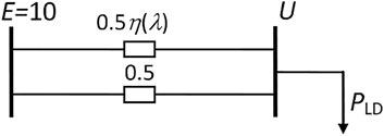
In order to clearly illustrate the branch breaking power flow calculation problem in the power system, the branch breaking power flow calculation of the simple DC circuit shown in Figure 1 is analyzed.
The branch parameter in Figure 1 is the admittance (e.g., 0.5), and η(λ) is the breaking function. λ is assumed as the parameter of the branch circuit breaking process. The admittance of one of the branches is multiplied by the breaking function η(λ), and 0.5η(λ) indicates that the branch is to be disconnected. If the branch admittance is zero, the corresponding branch state is disconnected. Among them, the continuous variation interval of λ is [0,1].
The physical meaning of the disconnection function is the transition method selected by the branch from normal operation to disconnection, and its function value describes the degree to which this process is carried out. Now suppose that there is a breaking function η(λ), as described in Wu et al. (2020), then the continuous breaking function can be set as the following:
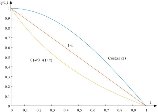
Obviously, when λ = 0 and η(0) = 1, it corresponds to the normal state of the system; otherwise, if λ = 1 and η(1) =0, it corresponds to open a branch. If (1-λ) in Eq. 1a is adopted, it is a linear breaking function. In Eq. 1b, (1-λ)/(1+λ) is a nonlinear breaking function. Suppose the nonlinear function conforms to the cos(πλ/2) nonlinear relationship, then the change curve of the continuous breaking function η(λ) is as shown in Figure 2.
It can be seen from Figure 2 that the change rules of different breaking functions are different.
Their initial and final values are consistent. The function η(λ) = cos(πλ/2) can also play the role of continuous breaking. But it has no practical value and is only used for curve comparison. Therefore, the power equation can be listed from the circuit.
Equation 2 can be organized into the following form:
From Eq. 3, we know that when λ = 0→1, U is a composite function with respect to the parameter λ, that is, U=U (η(λ)).
Then, we analyzed a branch broken first in Figure 1. Assuming load power is constant (PLD = constant). We expand the voltage U into the Taylor series of the parameter λ, which combined with the nonlinear breaking function η(λ). Just taking the second-order Taylor series as an example, Eq. 3 is the second derivative of λ, then we have
In Figure 1, when λ = 0, let the initial state of the system be: PLD = 9 and U0 = 9. It can be solved by the following formula:
In addition, the third-order Taylor series coefficient a3 can be obtained according to the abovementioned analogy. Then, the third-order Taylor series of U concerning λ is obtained as follows:
In Eq. 6, let λ = 1, then the breaking voltage can be obtained immediately.
Specifically, the different breaking function η(λ) is selected, which has been largely affected by the convergence rate of the Taylor series. The influence of the calculation results of the breaking voltage under different breaking functions analyzed as follows is shown in Table 1.
It can be seen from Table 1 that the voltage calculation result error reaches 3.73% by applying the linear breaking function (1-λ), obviously far from meeting the precise calculation requirements. After applying the nonlinear breaking function (1-λ)/(1+λ), voltage accuracy improved by more than one order of magnitude, and the calculation error of the three-stage number is only|Δ| = 0.35%. It is proved that the choice of the breaking function has a great influence on the accuracy of the calculation result. Therefore, the nonlinear breaking function of Eq. 1b is used in the following text, which is the important significance of the nonlinear breaking function proposed in this study. In the actual system, especially the larger scale power system with the stronger actual nonlinear characteristics, there are different requirements on the choice of breaking function. Research on how to choose a better breaking function will be carried out in the follow-up studies.
Calculation Method of the Network Disconnection Line Power Flow
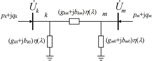
Break analysis of any branch of the power system, such as the case of the grid breaking one line and the analysis process of breaking two or more grid lines, is completely consistent with this. Let the continuous breaking function be η(λ)=(1-λ)/(1+λ), then the breaking line is Lk-m. Then, the ∏-type equivalent circuit for breaking the line is shown in Figure 3.
From Figure 3, breaking one line is equivalent to breaking three branches at the same time, and each branch admittance is a function of the breaking parameter λ. In the process of line disconnection, since four elements in the admittance matrix Y are functions of λ, the power flow equation also includes the parameter λ, which is as follows:
Since four elements in the network admittance matrix Y are functions of λ, then in the elements of the power flow Jacobian matrix J, four elements in corresponding positions have both voltage variables and breaking functions η(λ), which is as follows:
The Jacobian matrix J' can be equivalently added to two matrices, by which we can get
In the formula, J1 and J2 are, respectively,
It should be noted that only when λ = 0 and η(0) =1, then J′ = J1+J2.
For the convenience of description, the power flow equation in polar coordinates is used to deduce the calculation of the breaking power flow. Similarly, the power flow equation in rectangular coordinates can also be used for derivation. The power flow equation of the power system is as follows:
In Eq. 12,
It can be seen from Eq. 12 that the phase angle δ and voltage U of each node in the system are functions of the parameter λ, so Eq. 12 can be derived from λ. Here,
In Eq. 13, when λ = 0 and η(0) = 1.
At this time, J1+J2 = J, J is the Jacobian matrix that was obtained before the line was broken and no need to recalculate; therefore,
In addition, H is
In Eq. 15, the elements pk, qk, pm, and qm happen to be the power injected into each end of the breaking line, respectively (see Figure 3). The calculation formula is shown in Appendix A.
Therefore, the first derivative of X to λ before the line is disconnected (i.e., λ = 0) and is as follows:
Eq. 13 continues to take the derivative of λ:
Since J1 = ∂H/∂X, there are two terms in Eq. 17 that are completely equal, but the expressions are different.
Therefore, when λ = 0 and η(0) = 1, Eq. 17 can be simplified as follows:
Specifically, dJ’/dλ in Eq. 17 and dJ/dλ in Eq. 19 are, respectively,
Therefore, the second derivative of X concerning λ is as follows:
After considering Eqs 17 and 19, re-expression of Eq. 14, and the third derivative of the voltage U concerning λ, see Appendix C. After calculating the derivatives of X concerning λ from Eqs 18 and 21, the voltage of each node after the disconnection of line can be calculated according to the Taylor expansion:
In the Taylor series, let λ =1, the calculation expressions of the voltage amplitude and phase angle of each node are obtained as follows:
It can be seen that since J is exactly the Jacobian matrix of the convergence of power flow calculation before line interruption, its inverse matrix already exists, and various interruption power flow calculations use the inverse of the same Jacobian matrix, so its calculation amount is equivalent to that of traditional interruption, like the DC method or compensation method for load flow calculation.
Power Flow Calculation for Power Interruption
During the disconnection process of the power supply branch, the node admittance matrix of the power system remains unchanged, but the injected power of the node changes. The analysis results showed that the calculation accuracy of the Taylor series method does not depend strongly on the power interruption function η(λ). When η(λ)=(1-λ)/(1+λ), the interrupted power flow results with higher accuracy can also be obtained by fitting the third-order Taylor series. This is because the interruption of the power supply will not affect the system network structure but will only change the initial value of the power flow equation. By applying the method in this study, the expected accident set can be scanned accurately and quickly, to directly judge whether the breaking power flow meets the safety requirements, and the precise correction process with a large amount of calculation is omitted.
Simulation Calculation and Analysis
Power Flow Calculation for Breaking Branches
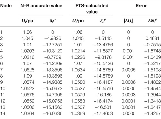
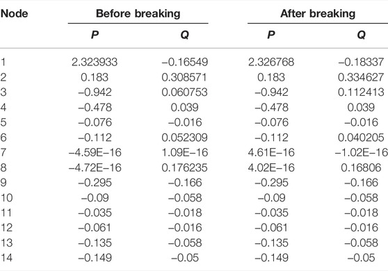
In this study, the IEEE14 node calculation example is used to calculate the voltage value of each node after the line is disconnected. One result is according to the Taylor expansion-based breaking power flow method (FTS) proposed in this work It was compared with the real value calculated by the Newton–Raphson method (N–R). The comparison results are shown in Table 2. The system power changes before and after the disconnection of lines 3–4 and is shown in Table 3.
According to Table 2 and Table 3, it can be observed that when compared with the N–R power flow method, the breaking power flow calculation method based on Taylor series fitting proposed in this study differs in the voltage value and phase angle of each node after the calculation system line is broken very small, and the difference in voltage value is 0–0.005 p.u, the difference between the power angle is 0–1.5°, the active and reactive values are the same, and it is proved that the proposed method has high accuracy in calculating the power flow distribution of the system after the line is disconnected. Moreover, the method in this study does not need to correct the calculation process of precise matrix elements, which greatly speeds up the analysis and calculation speed, and its theoretical significance and application value are very significant.
N-1 Static Security Rapid Analysis
In particular, the method in this study can be easily extended to the case of k-circuit breaking and realizes the static safety and fast analysis of the power system N-k. Table 4 shows the calculation of the power flow of the N–R method after branch N-1 and the comparison results with the method in this study.

TABLE 4. Calculation results of branch breaking power flow of the Newton–Raphson method and comparison with the proposed method.
From the results in Table 4, it can be found that the error between the breaking power flow calculated by the method in this study and that calculated by the N–R method is very small, the node voltage amplitude error and voltage phase angle error are in the ranges of 0–0.01 and 0–0.0095, respectively, and the calculation error will not affect the estimation of the system operating state. In addition, the N–R method takes 2.9607 s to calculate the breaking power flow for all branches, the total time consumption of this method is 0.3312 s, and the total analysis calculation time is only 11.2% of the traditional method. It can be seen that the calculation speed of the method in this study is greatly accelerated. Therefore, this method is more suitable for application and rapid fault scanning to identify the degree of impact of faults on system stability.
Conclusion
This study proposed a breaking power flow calculation method based on Taylor series fitting. Compared with the DC power flow method, this method has advantages such as precise calculation results and the ability to obtain voltage amplitude and reactive power faster. Furthermore, the proposed method can also be generalized to the case of breaking multiple loops and realize the fast and accurate calculation of the power system N-k breaking power flow. Compared with the traditionally expected accident set scanning based on the N–R method, using this method to scan the accident set does not need an iterative solution. It only needs scanning to obtain the accurate data of the fault severity ranking and the node voltage after breaking the line. Therefore, the calculation speed meets the requirements of online static security analysis.
Data Availability Statement
The original contributions presented in the study are included in the article/Supplementary Materials; further inquiries can be directed to the corresponding author.
Author Contributions
SL: Find out the problems, conceive the overall framework of the article and put forward the main points. XZ: Process data and develop simulation programs, and analyze simulation results. WL: Revising the critical content for the selection of breaking function and the allowable range of node voltage calculation error. Md TH: Consult the literature to find the relevant materials of the article and participate in the writing of the first draft of the manuscript. ZZ: Oversight and leadership responsibility for the research activity planning and execution.
Conflict of Interest
The authors declare that the research was conducted in the absence of any commercial or financial relationships that could be construed as a potential conflict of interest.
Publisher’s Note
All claims expressed in this article are solely those of the authors and do not necessarily represent those of their affiliated organizations, or those of the publisher, the editors, and the reviewers. Any product that may be evaluated in this article, or claim that may be made by its manufacturer, is not guaranteed or endorsed by the publisher.
Acknowledgments
The authors are grateful to Hongying He and Hu Pengyu for providing basic data and simulation software for this article. In addition, the authors are also grateful for the financial support from the National Natural Science Foundation of China (Grant No.51777179) and the State Grid Hunan Electric Power Co., Ltd. Science and Technology Project (No. 5216A521003C).
References
Capitanescu, F., Glavic, M., Ernst, D., and Wehenkel, L. (2007). Contingency Filtering Techniques for Preventive Security-Constrained Optimal Power Flow. IEEE Trans. Power Syst. 22 (4), 1690–1697. doi:10.1109/tpwrs.2007.907528
Chatterjee, I. (2021). Artificial Intelligence and Patentability: Review and Discussions. Int. J. Mod. Res. 1, 15.
Dhiman, G., and Kaur, A. (2019). STOA: a Bio-Inspired Based Optimization Algorithm for Industrial Engineering Problems. Eng. Appl. Artif. Intell. 82, 148–174. doi:10.1016/j.engappai.2019.03.021
Duan, N., Huang, C., Sun, C. -C., and Min, L. (2022). Smart Meters Enabling Voltage Monitoring and Control: The Last-Mile Voltage Stability Issue. IEEE Trans. Industrial Inf. 1 (18), 677–687. doi:10.1109/tii.2021.3062628
England, B. S., and Alouani, A. T. (2020). Real Time Voltage Stability Prediction of Smart Grid Areas Using Smart Meters Data and Improved Thevenin Estimates. Int. J. Electr. Power & Energy Syst. 122, 106189. doi:10.1016/j.ijepes.2020.106189
Fliscounakis, S., Panciatici, P., Capitanescu, F., and Wehenkel, L. (2013). Contingency Ranking with Respect to Overloads in Very Large Power Systems Taking into Account Uncertainty, Preventive, and Corrective Actions. IEEE Trans. Power Syst. 28 (4), 4909–4917. doi:10.1109/tpwrs.2013.2251015
Kaplunovich, P. A., and Turitsyn, K. S. (2013). Fast Selection of N−2 Contingencies for Online Security Assessment. in 2013 IEEE Power & Energy Society General Meeting (New York, NY), 1–5.
Kaur, S., Awasthi, L. K., Sangal, A. L., and Dhiman, G. (2020). Tunicate Swarm Algorithm: A New Bio-Inspired Based Metaheuristic Paradigm for Global Optimization. Eng. Appl. Artif. Intell. 90, 103541. doi:10.1016/j.engappai.2020.103541
Kumar, R., and Dhiman, G. (2021). A Comparative Study of Fuzzy Optimization through Fuzzy Number. Int. J. Mod. Res. 1, 1.
Li, S., Hou, J., and Li, J.. DNN-based Distributed Voltage Stability Online Monitoring Method for Large-Scale Power Grids. Front. Energy Res. 33 (4), 4189. doi:10.3389/fenrg.2021.625914
Li, S., Tan, Y., Li, C., Cao, Y., and Jiang, L.. A Fast Sensitivity-Based Preventive Control Selection Method for Online Voltage Stability Assessment. IEEE Trans. Power Syst. 33 (4), 4189. doi:10.1109/TPWRS.2017.2776968
Liu, H., Xie, X., Zhang, C., Li, Y., Liu, H., and Hu, Y. Quantitative SSR Analysis of Series-Compensated DFIG-Based Wind Farms Using Aggregated RLC Circuit Model. IEEE Trans. Power Syst. 32, 474–483. doi:10.1109/tpwrs.2016.2558840
Lu, T., Wang, Z., Ai, Q., and Lee, W.-J. (2017). Interactive Model for Energy Management of Clustered Microgrids. IEEE Trans. Ind. Appl. 53 (3), 1739–1750. doi:10.1109/tia.2017.2657628
Meng, Z. J., Xue, Y., and Lo, K. L. (2006). A New Approximate Load Flow Calculation Method for Contingency Selection. in 2006 IEEE PES Power Systems Conference and Exposition (Nanjing), 1601. doi:10.1109/PSCE.2006.296152
Padiyar, K., and Rao, S. S. (1996). Dynamic Analysis of Small Signal Voltage Instability Decoupled from Angle Instability. Electr. Power &Energy Syst. 18 (7), 445.
Peyghami, S., Palensky, P., and Blaabjerg, F. (2020). An Overview on the Reliability of Modern Power Electronic Based Power Systems. IEEE Open J. Power Electron. 1 (1), 34–50. doi:10.1109/ojpel.2020.2973926
Sachdev, M. S., and Ibrahim, S. A. (1974). A Fast Approximate Technique for Outage Studies in Power System Planning and Operation. IEEE Trans. Power Apparatus Syst. (4), 1133. doi:10.1109/TPAS.1974.294059
Shukla, S. K., Gupta, V. K., Joshi, K., Gupta, A., and Singh, M. K. (2022). Self-aware Execution Environment Model (SAE2) for the Performance Improvement of Multicore Systems. Int. J. Mod. Res. 2 (1), 17.
Vargas, L., and Quintana, V. H. (1990). A Fast and Reliable Decoupled Load Flow Method in Rectangular Coordinates.” in Proceedings of the Twenty-Second Annual North American Power Symposium, 94.
Wu, C., Fei, L. I., and Liu, G. (2020). Breaking Power Flow Calculation Based on Linear Voltage Function and Breaking Function Selection, Electr. Power Autom. Equip. 40, 211. doi:10.16081/j.epae.202008026
Yun, Z., Cui, X., and Ma, K. (2019). Online Thevenin Equivalent Parameter Identification Method of Large Power Grids Using LU Factorization. IEEE Trans. Power Syst. 34 (6), 4464. doi:10.1109/TPWRS.2019.2920994
Keywords: power system, static safety analysis, breaking power flow, fast and accurate calculation, nonlinear breaking function
Citation: Li S, Zhao X, Liang W, Hossain MT and Zhang Z (2022) A Fast and Accurate Calculation Method of Line Breaking Power Flow Based on Taylor Expansion. Front. Energy Res. 10:943946. doi: 10.3389/fenrg.2022.943946
Received: 14 May 2022; Accepted: 07 June 2022;
Published: 14 July 2022.
Edited by:
Tianguang Lu, Shandong University, ChinaReviewed by:
Gaurav Dhiman, Government Bikram College of Commerce Patiala,(Punjab) IndiaNing Li, Xi’an University of Technology, China
Mao Tan, Xiangtan University, China
Copyright © 2022 Li, Zhao, Liang, Hossain and Zhang. This is an open-access article distributed under the terms of the Creative Commons Attribution License (CC BY). The use, distribution or reproduction in other forums is permitted, provided the original author(s) and the copyright owner(s) are credited and that the original publication in this journal is cited, in accordance with accepted academic practice. No use, distribution or reproduction is permitted which does not comply with these terms.
*Correspondence: Shuaihu Li, bGlzaHVhaWh1MjAxMEAxMjYuY29t
 Shuaihu Li
 Xiang Zhao