
94% of researchers rate our articles as excellent or good
Learn more about the work of our research integrity team to safeguard the quality of each article we publish.
Find out more
ORIGINAL RESEARCH article
Front. Energy Res. , 09 August 2022
Sec. Electrochemical Energy Storage
Volume 10 - 2022 | https://doi.org/10.3389/fenrg.2022.943113
 Youngseung Na1†
 Min Gwan Ha2,3†Hyun S. Park2Hee Young Park2Hyoung-Juhn Kim2,4Dirk Henkensmeier2,4
 Sung Jong Yoo2,4,5Jin Young Kim2,4,5So Young Lee2Jong Hyun Jang2,4,5*
Greenhouse gases such as carbon dioxide and methane are responsible for intensifying global warming. Consequently, a reduction in power plant outputs and an increase in capture and storage on-site are required to reduce greenhouse gas emissions. Recently, research has focused on an electrochemical CO2 reduction method because the amount of CO2 reduction can be controlled by adjusting the operating voltage. However, to scale up the electrochemical system while maintaining a high conversion rate in a large cell, a suitable flow field of the cell must be optimized. The transparent cell structure presented in this study allows visualization of the distribution of the two-phase flow. Accordingly, dual-flow channels consisting of main and sub-channels have been designed. Furthermore, multiple configurations of the dual-flow channels and locations of the catalyst layer have been compared. The interdigitated sub-channels and inverted layered cell structures can supply gas and liquid to the catalyst layer via distinct pathways, allowing for uniform flow distribution to each channel.
For decades, global warming, which has been attributed to greenhouse gases such as hydrofluorocarbons, nitrous oxide, methane, and carbon dioxide, has caused significant damage to the ecosystem. Carbon dioxide is commonly recognized as one of the most potent greenhouse gases (Lashof and Ahuja, 1990). Using regenerative energy, increasing the efficiency of power generation, or carbon capture and sequestration (CCS) in the atmosphere can reduce carbon dioxide emissions. The International Energy Agency anticipates that CCS technology will reduce CO2 emissions by approximately 19% by 2050 (Taylor, 2010). The CCS process consists of capturing, compressing, transporting, and storing carbon dioxide, and all of these steps have geological and economic disadvantages; for instance, transporting compressed carbon dioxide gas to a distant location incurs additional expense. Carbon utilization, such as mineralization, chemical conversion, electrochemical conversion, or biological conversion, is currently more advantageous than simple carbon capture and sequestration because converting carbon dioxide gas into chemicals with a higher value is economically advantageous and sustainable (Lu and Jiao, 2016). In particular, electrochemical conversion technology controls the precise amount of valuable chemicals through voltage control, whereas chemical conversion technology requires a large pilot plant site and high temperatures. Tufa et al. (2020) classify electrolysis technologies as liquid electrolyte, proton exchange membrane (PEM), anion exchange membrane (AEM), and solid-oxide electrolysis. PEM electrolysis is one of the three electrolysis technologies that permit low-overpotential reactions that can draw a high current density in low pH solutions. Numerous researchers have developed the technology to electrochemically convert CO2 into useful chemical compounds such as formate (Li and Oloman, 2005; Li and Oloman, 2006; Li and Oloman, 2007), formic acid (Wang et al., 2013; Zhang et al., 2014; Lu et al., 2016), methanol (Albo and Irabien, 2016), methane (Aeshala et al., 2013), and carbon monoxide (Rosen et al., 2011).
Carbon monoxide or syngas has proven to be one of the most cost-effective CO2-reduction products owing to the market price of carbon monoxide being significantly higher than that of other liquid products (Lu and Jiao, 2016). Technology development for carbon dioxide reduction includes catalyst research for high reduction efficiency and cell structure design for scaling up. Catalysts for the electrochemical reduction of CO2 are actively being studied from various perspectives. The size of the Ag catalyst has been optimized for selectivity by Salehi-Khojin et al. (2013). An oxide-derived Ag catalyst involving a nanoporous structure exhibits a higher conversion rate (Chen et al., 2012; Lu et al., 2014) than the nanoparticle catalyst. Despite the importance of cell structure design for commercialization, cell structure design has not been the subject of extensive study thus far.
In the cathodes of PEM electrolyzers, CO2 molecules react electrochemically with migrated protons and electrons to form CO (Eq. 1), as well as H2 through hydrogen evolution reactions (HER, Eq. 2).
Potassium hydroxide solution is supplied at the anode to increase the reaction rate of water electrolysis (Verma et al., 2016). Split water stimulates proton production at the anode.
To convert carbon dioxide into a carbonate ion, the CO2 reduction cell requires a liquid electrolyte such as potassium bicarbonate solution. As shown in Eq. 1, the electrolyte can enhance the CO2 gas reaction (Delacourt et al., 2008). The formation of a three-phase boundary with CO2 necessitates the uniform distribution of gaseous and liquid-phase reactants on the catalyst surface. Accordingly, it is required that practical cell structures be enlarged and stacked without performance degradation. Several structure designs have been proposed; however, further research is necessary to optimize the two-phase flow onto the catalyst surface.
Dufek et al. (2011) proposed a filter-pressed cell that supplies carbon dioxide gas through additional mesh and potassium sulfate solution in the channels. A pressurized system with a separate CO2 supply path to the catalyst has high faradaic efficiency; however, it is difficult to stack cells with mesh on the top owing to the presence of multiple layers. To inhibit hydrogen evolution reactions, Delacourt et al. (2008) utilized a buffer layer type cell with a soaking porous material between the catalyst layer and the membrane. However, when KOH solution is used as the anolyte, the potassium concentration at both electrodes may not be stable because of a discontinuous supply of potassium bicarbonate. A microfluidic reactor, which utilized a flowing liquid electrolyte without a separating membrane between the anode and cathode, has been proposed (Thorson et al., 2013; Wu et al., 2015; Kim et al., 2016); however, it has trouble producing pressurized stacks.
In this study, an alternative electrochemical cell with a dual-flow channel structure for electrochemical CO2 reduction with PEM electrolytes was proposed. To test the orientation effect of separately supplying the two-phase flow, the distribution of the two reactants and products was qualitatively evaluated via a transparent cell structure, as described by Yang et al. (2005). The dual-flow channel is anticipated to distribute the carbon dioxide gas and potassium bicarbonate solution separately on the catalyst layers. To enlarge the three-phase boundary, a combination of the dual-flow channel and a membrane electrode assembly (MEA) structure was examined. Dual-flow channels in a single layer have been reported to increase the two-phase reactant reaction rate. In addition, the compact structure would be advantageous for large-scale stack construction and pressurized operations.
Ag black (576,832-5G 99.5 wt%, Sigma-Aldrich, United States) was employed as the cathode catalyst with Nafion ionomer (274,704-25ML, Sigma-Aldrich, United States). Catalyst ink with isopropanol was sprayed on a gas diffusion layer (TGP-H-090, Toray, Japan). IrO2 (43,396-5G 99.99 wt%, Alfa Aesar, United States) was chosen as the anode catalyst and sprayed on titanium foam with Nafion ionomer. Each catalyst was loaded with 1 mg/cm2 at each electrode, which had a 9 cm2 active area on the diffusion layers. The anode and cathode electrodes sandwiched an electrolyte membrane (NR212, DuPont, United States) to create a membrane electrode assembly (MEA) for carbon dioxide reduction and hydrogen evolution at the cathodes.
The transparent cell structure introduced by Yang et al. (2005) was utilized to visualize turbulent flow in the channels. The silicone gasket (400 μm, CNL, Korea), sealing gas and liquid products, are illustrated in Figure 1A. Titanium channel plates, coated with platinum (0.3 μm) to prevent corrosion, guided the reactants for distribution over the entire catalyst layer and extracted products from the gas diffusion layers. Edge rods on each side of the perforated channel plates collected electricity. To visualize two-phase flow in the channels, transparent acrylic glass end plates were used. Polyether ether ketone fittings were used to resist alkaline solution corrosion. The assembled transparent cell is shown in Figure 1B.
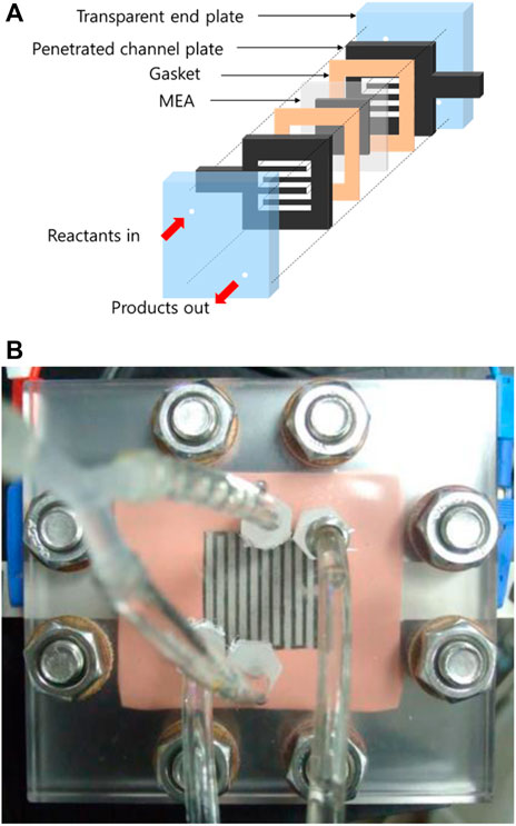
FIGURE 1. (A) Schematic and (B) picture of a membrane electrode assembly with a proton exchange membrane in a transparent cell fixture.
As illustrated in Figure 2, a peristaltic pump (L/S easyload 7518-10, Masterflex, United States) and a diaphragm pump (SIMDOS, KNF, Switzerland) supplied potassium bicarbonate solution and potassium hydroxide solution, respectively. The carbon dioxide gas was regulated by the flow meter’s ball valve (RMA-151-SSV, Dwyer, United States). A potentiostat (HCP-803, Biologic, France) controlled the operating voltage of the electrolysis cells and measured their electric current. After water trapping, the products of cathodic reactions in the cell were analyzed by using a gas chromatography system (7890B GC system, Agilent Technologies, United States).
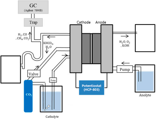
FIGURE 2. Schematic representation of a carbon dioxide reducing system with a proton exchange membrane.
The electrolysis cell was supplied with 10 cm3/min carbon dioxide, 10 cm3/min of a carbon dioxide-saturated 0.5 M potassium bicarbonate solution to the cathode, and 10 cm3/min of 0.5 M potassium hydroxide to the anode. The reduction of carbon dioxide and electrolysis of water occurred at atmospheric temperature and pressure. Carbon dioxide, which was purged for at least 24 h, was substituted for nitrogen, which had already been dissolved in the potassium bicarbonate solution. The operating voltage was increased from 0.1 to 1.8 V every minute by 0.1 V, excluding the sampling period. After 30 min of each voltage step, product gases such as hydrogen, carbon monoxide, and methane were analyzed by the gas chromatography system at 1.8, 2.2, 2.6, and 3.0 V, respectively. In addition, the operating voltage between the samples was increased by 0.1 V per minute.
It is difficult to quantify the flow regime of carbon dioxide gas and potassium bicarbonate solution in channels. By using the transparent cell, the two-phase flow can be observed, and the inferior orientation toward CO evolution can be avoided.
To evaluate the effect of gravity on two-phase separation, the dual-flow type cell was tested in two different orientations, lying down and standing up. As shown in Figure 3A, potassium bicarbonate solution diffuses from the sub-channels to the main channels in the prone position with the cathode facing upward. Carbon dioxide gas passes through the primary channel, carrying the liquid solution with it. Throughout the time, the main channels are occupied by the gas phase. In contrast, with the cell in a standing position, buoyant gas fills the upper side of the channels and liquid fills the opposite side of the cell, as depicted in Figure 3B. On the top catalyst layer, the supporting electrolyte is insufficient for the reaction, whereas the gas reactant on the bottom is insufficient.
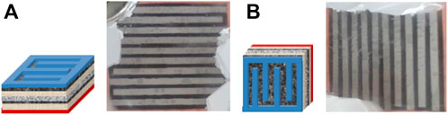
FIGURE 3. Schematics and photographs depicting two-phase flow in cathode channels of (A) a supine cell (cathode up) and (B) a standing cell (vertical channel) at a cell voltage of 3.0 V.
To quantify the orientation effect, Figure 4 compares the CO faradaic efficiency at four different positions with the same voltage, 3.0 V. The cathode-up and anode-up orientations were evaluated in the supine position, whereas the vertical channel and horizontal orientations were evaluated in the standing position. The lying-down cell with the cathode facing up (cathode up) has the highest CO faradaic efficiency of the four positions. In a horizontal cell with the cathode facing downward, gas fills the porous diffusion layer and liquid flows through the main channel. In such a scenario, the supporting electrolyte cannot transport protons to the cathode catalyst. Therefore, the cathode-down orientation has a lower CO faradaic efficiency than that of the cathode-up orientation. Additionally, standing cells are less efficient than lying cells. One side has a lack of electrolytes, whereas the other lacks carbon dioxide. Consequently, the active area decreases to half that of the cathode-up orientation. All subsequent cell tests in this study were conducted with in the cathode-up orientation.
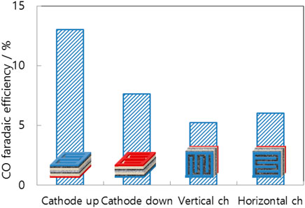
FIGURE 4. CO faradaic efficiency of differently positioned MEAs (cathode up/cathode down: supine cell with cathode face up/down, vertical channel/horizontal channel: standing cell with vertical/horizontal channels) at a cell voltage of 3.0 V.
A dual-flow cell is suitable for distributing two-phase reactants uniformly on the catalyst layer. The main channel is a single serpentine channel from the inlet to the outlet, while the sub-channel is a series of dead-end interdigitated channels between the grooves of the main channel. As shown in Figure 5A, when carbon dioxide gas flows in the main channel, potassium bicarbonate solution flows in the sub-channel [Dual (gas)-A]. Type A indicates that the catalyst layer is located between the channels and gas diffusion layer (GDL) , and not on top of the membrane as in type B. The solution is unable to pass through the sub-channel walls; however, it diffuses through the diffusion layer beneath the catalyst layer. To transport protons from the membrane to the catalyst layer, the diffusion layer is filled with a supporting electrolyte. On the catalyst layer, the proton can encounter highly concentrated carbonate ions, which can increase the CO evolution rate. This is why the catalyst layer is situated between the channels and the membrane.
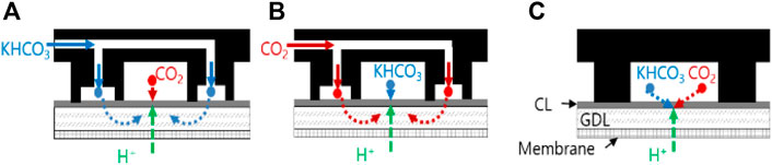
FIGURE 5. Schematic representation of (A) the dual-flow type cell with gas in the main channel [Dual (gas)-A], (B) the dual-flow type cell with liquid in the main channel [Dual (liq)-A], and (C) the single-channel type cell [Single (mix)-A].
Conversely, the liquid electrolyte flows through the main channel and the gaseous reactant passes through the sub-channel in the Dual (liq)-A configuration, as shown in Figure 5B. The reference flow path is a serpentine channel on the GDL that distributes gas and liquid to the catalyst layer [Single (mix)-A (Figure 5C)], highly similar to that of conventional fuel cells or electrolytic cells (Delacourt et al., 2008). The conventional arrangement is appropriate for supplying single-phase reactants such as hydrogen gas or liquid water to the catalyst layer.
The dual-flow cells demonstrate higher performance than the Single (mix)-A cell because the two-phase reactants are mixed separately near the catalyst layer (Figure 6A). In particular, liquid electrolyte spreads across the entire catalyst layer for the dead-end flow field of the sub-channels. In a Dual (gas)-A type separator, carbon dioxide gas enters the main channel while potassium bicarbonate solution flows through the sub-channels on both sides of the edges. As depicted in Figure 7, reactants diffuse into the GDL because the sub-channels are blocked by channel walls acting as dead ends. Finally, the reactants combine on the cathode layers in the main channel. While gas flows along the main channels, the catalyst layer is surrounded by carbon dioxide gas on the top and potassium bicarbonate solution on the bottom because of gravity. The catalyst, electrolyte, and gas reactant form the optimal structure for the three-phase boundary of the carbon dioxide reduction reaction. The structurally enlarged active area dramatically increases the CO faradaic efficiency. As shown in Figure 6B, the Dual (gas)-A cell has approximately seven times the CO faradaic efficiency of the other structures. Owing to the dead-end channels, liquid from the interdigitated channels in Dual (liq)-A is forced to pass through the diffusion layer. The diffusion of the liquid is observable through the transparent cell. The supporting electrolyte, present as a liquid phase beneath the catalyst layer, facilitates proton contact with the cathode catalyst and carbon dioxide prior to hydrogen reduction. Without the supporting electrolyte, the proton would be reduced to hydrogen, in a similar reaction to that observed in electrolysis cells.
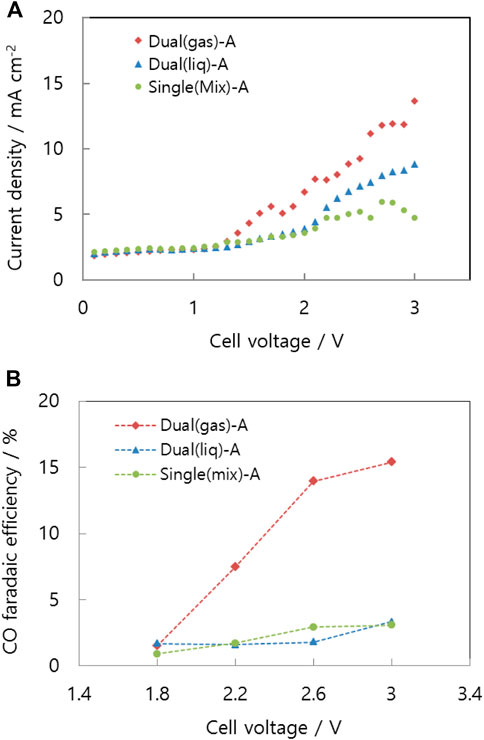
FIGURE 6. (A) Voltage-current curve and (B) CO faradaic efficiency of the differently structured cells: Dual (gas)-A, Dual (liq)-A, and Single (mix)-A.
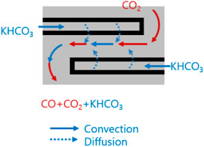
FIGURE 7. Conceptual flow direction of the reactants at the integrated channels.
Generally structured MEAs such as fuel cells or electrolytic cells, in which the catalyst layer is positioned between the diffusion layer and the membrane, are evaluated with dual-flow cells and the single-channel cell, as depicted in Figure 8.
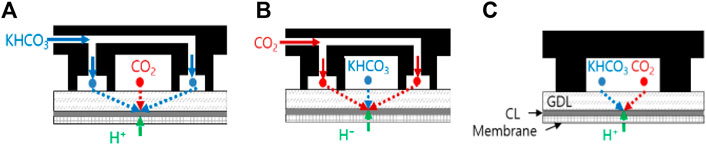
FIGURE 8. Schematic diagrams of (A) the dual-flow type cell with gas in the main channel [Dual (gas)-B], (B) the dual-flow type cell with liquid in the main channel [Dual (liq)-B], and (C) the single-channel type cell [Single (mix)-B].
Figure 9A represents the current-voltage curves of the Dual (gas)-B, Dual (liq)-B, and Single (mix)-B cells. The three curves are mostly identical, and the CO faradaic efficiencies given in Figure 9B are less than 5% in any case, indicating that more than 95% of the cathode products is hydrogen. Before making contact with the carbon dioxide, protons moved through the electrolyte membrane, arrived at the cathode, and were reduced to hydrogen.
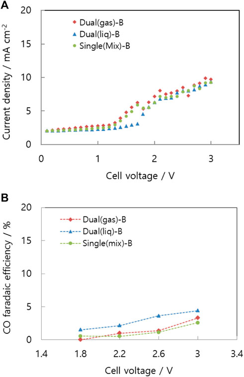
FIGURE 9. (A)Voltage-current curve and (B) CO faradaic efficiency of differently structured cells: Dual (gas)-B, Dual (liq)-B, and Single (mix)-B.
In conventional MEAs, liquid electrolyte flows through a diffusion layer to the catalyst layer. Consequently, similar amounts of reactions occur on the cathode, regardless of the channel structure and separate reactant supply.
The Dual (gas)-A cell has a structure optimized for gravity-based gas and liquid delivery to the catalyst layer. Stable separation of the two-phase flow occupies a significantly larger peripheral active area than other structures. To allow comparison of the yield of carbon monoxide, Figure 10 depicts the partial current densities of carbon monoxide from all structures at 3.0 V. Multiplying the total current density and the CO faradaic efficiency yields the partial current density. Single serpentine channels [Single (mix)-A] generate the least amount of carbon monoxide relative to the other structures.
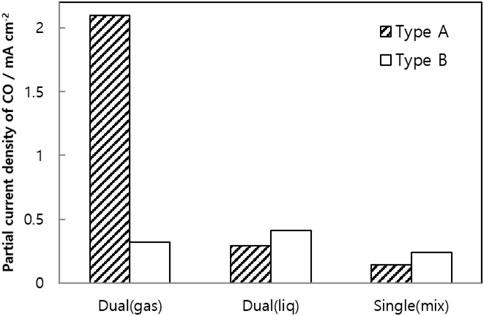
FIGURE 10. CO partial current density of differently structured cells composed of single serpentine or integrated channels with liquid or gas phase [Mixed supply, Single (mix)], liquid in the main channel with gas in the sub-channels [Dual (liq)], or gas in the main channel with liquid in the sub-channel [Dual (gas)] with the fluid in the main channel contacted by the catalyst layer (Type A) or the gas diffusion layer (Type B).
The carbon dioxide reduction cell was supplied with a two-phase flow consisting of a liquid electrolyte and a gaseous reactant, carbon dioxide, whereas other electrolysis cells require a single phase of water or alkaline solution. A dual-flow channel in a single layer uniformly distributed the two-phase reactants to the cathode. However, a single serpentine channel for the gaseous reactants and interdigitated sub-channels for the liquid electrolyte, bearing an inverted cell structure, exhibited the highest performance. In contrast to other structures, the newly presented cell structure enhanced the CO faradaic efficiency. Although other structures also provided two-phase flow separately, gravity did not maximize the three-phase boundary, and the performance of the other cell structures was poor. In other locations, the three-phase boundary did not completely cover the catalyst layer. In this manner, the independent-supply structure in a single layer enables uniform distribution of the reactants to each cell in a stack for scale up.
The raw data supporting the conclusions of this article will be made available by the authors, without undue reservation.
YN: conceptualization, writing, MH: experiment, HSP: review and editing, HYP: methodology, H-JK: funding acquisition, DH: investigation, SY: methodology, JK: review and editing, SL: methodology, JJ: supervision.
This research was supported by the National R&D Program through the National Research Foundation of Korea (NRF) funded by the Ministry of Science and ICT (NRF-2019M3E6A1063674). This research was also supported by the Korea Institute of Science and Technology (No. 2E31871). This research was supported by the National R&D Program through the National Research Foundation of Korea (NRF) funded by the Ministry of Science, ICT and Future Planning (NRF-2020M1A2A2080880).
The authors declare that the research was conducted in the absence of any commercial or financial relationships that could be construed as a potential conflict of interest.
The handling editor SK declared a shared parent affiliation with the authors MG, HSP, HYP, H-JK, DH, SJY, JYK, and SYL at the time of review.
All claims expressed in this article are solely those of the authors and do not necessarily represent those of their affiliated organizations, or those of the publisher, the editors, and the reviewers. Any product that may be evaluated in this article, or claim that may be made by its manufacturer, is not guaranteed or endorsed by the publisher.
Aeshala, L. M., Uppaluri, R. G., and Verma, A. (2013). Effect of Cationic and Anionic Solid Polymer Electrolyte on Direct Electrochemical Reduction of Gaseous CO2 to Fuel. J. CO2 Util. 3-4, 49–55. doi:10.1016/j.jcou.2013.09.004
Albo, J., and Irabien, A. (2016). Cu2O-loaded Gas Diffusion Electrodes for the Continuous Electrochemical Reduction of CO2 to Methanol. J. Catal. 343, 232–239. doi:10.1016/j.jcat.2015.11.014
Chen, Y., Li, C. W., and Kanan, M. W. (2012). Aqueous CO2 Reduction at Very Low Overpotential on Oxide-Derived Au Nanoparticles. J. Am. Chem. Soc. 134 (49), 19969–19972. doi:10.1021/ja309317u
Delacourt, C., Ridgway, P. L., Kerr, J. B., and Newman, J. (2008). Design of an Electrochemical Cell Making Syngas (CO+ H2) from CO2 and H2O Reduction at Room Temperature. J. Electrochem. Soc. 155 (1), B42–B49. doi:10.1149/1.2801871
Dufek, E. J., Lister, T. E., and McIlwain, M. E. (2011). Bench-scale Electrochemical System for Generation of CO and Syn-Gas. J. Appl. Electrochem 41 (6), 623–631. doi:10.1007/s10800-011-0271-6
Kim, B., Hillman, F., Ariyoshi, M., Fujikawa, S., and Kenis, P. J. A. (2016). Effects of Composition of the Micro Porous Layer and the Substrate on Performance in the Electrochemical Reduction of CO2 to CO. J. Power Sources 312, 192–198. doi:10.1016/j.jpowsour.2016.02.043
Lashof, D. A., and Ahuja, D. R. (1990). Relative Contributions of Greenhouse Gas Emissions to Global Warming. Nature 344 (6266), 529–531. doi:10.1038/344529a0
Li, H., and Oloman, C. (2006). Development of a Continuous Reactor for the Electro-Reduction of Carbon Dioxide to Formate - Part 1: Process Variables. J. Appl. Electrochem 36 (10), 1105–1115. doi:10.1007/s10800-006-9194-z
Li, H., and Oloman, C. (2007). Development of a Continuous Reactor for the Electro-Reduction of Carbon Dioxide to Formate - Part 2: Scale-Up. J. Appl. Electrochem 37 (10), 1107–1117. doi:10.1007/s10800-007-9371-8
Li, H., and Oloman, C. (2005). The Electro-Reduction of Carbon Dioxide in a Continuous Reactor. J. Appl. Electrochem 35 (10), 955–965. doi:10.1007/s10800-005-7173-4
Lu, Q., Rosen, J., Zhou, Y., Hutchings, G. S., Kimmel, Y. C., Chen, J. G., et al. (2014). A Selective and Efficient Electrocatalyst for Carbon Dioxide Reduction. Nat. Commun. 5 (1), 3242–3246. doi:10.1038/ncomms4242
Lu, Q., and Jiao, F. (2016). Electrochemical CO2 Reduction: Electrocatalyst, Reaction Mechanism, and Process Engineering. Nano Energy 29, 439–456. doi:10.1016/j.nanoen.2016.04.009
Lu, X., Leung, D. Y. C., Wang, H., Maroto-Valer, M. M., and Xuan, J. (2016). A pH-Differential Dual-Electrolyte Microfluidic Electrochemical Cells for CO2 Utilization. Renew. Energy 95, 277–285. doi:10.1016/j.renene.2016.04.021
Rosen, B. A., Salehi-Khojin, A., Thorson, M. R., Zhu, W., Whipple, D. T., Kenis, P. J. A., et al. (2011). Ionic Liquid-Mediated Selective Conversion of CO 2 to CO at Low Overpotentials. Science 334 (6056), 643–644. doi:10.1126/science.1209786
Salehi-Khojin, A., Jhong, H.-R. M., Rosen, B. A., Zhu, W., Ma, S., Kenis, P. J. A., et al. (2013). Nanoparticle Silver Catalysts that Show Enhanced Activity for Carbon Dioxide Electrolysis. J. Phys. Chem. C 117 (4), 1627–1632. doi:10.1021/jp310509z
Taylor, P. (2010). Energy Technology Perspectives 2010–scenarios and Strategies to 2050. Paris: International Energy Agency.
Thorson, M. R., Siil, K. I., and Kenis, P. J. A. (2013). Effect of Cations on the Electrochemical Conversion of CO2to CO. J. Electrochem. Soc. 160 (1), F69–F74. doi:10.1149/2.052301jes
Tufa, R. A., Chanda, D., Ma, M., Aili, D., Demissie, T. B., Vaes, J., et al. (2020). Towards Highly Efficient Electrochemical CO2 Reduction: Cell Designs, Membranes and Electrocatalysts. Appl. Energy 277, 115557. doi:10.1016/j.apenergy.2020.115557
Verma, S., Lu, X., Ma, S., Masel, R. I., and Kenis, P. J. A. (2016). The Effect of Electrolyte Composition on the Electroreduction of CO2to CO on Ag Based Gas Diffusion Electrodes. Phys. Chem. Chem. Phys. 18 (10), 7075–7084. doi:10.1039/c5cp05665a
Wang, H., Leung, D. Y. C., and Xuan, J. (2013). Modeling of a Microfluidic Electrochemical Cell for CO2 Utilization and Fuel Production. Appl. energy 102, 1057–1062. doi:10.1016/j.apenergy.2012.06.020
Wu, K., Birgersson, E., Kim, B., Kenis, P. J. A., and Karimi, I. A. (2015). Modeling and Experimental Validation of Electrochemical Reduction of CO2to CO in a Microfluidic Cell. J. Electrochem. Soc. 162 (1), F23–F32. doi:10.1149/2.1021414jes
Yang, H., Zhao, T., and Ye, Q. (2005). In Situ visualization Study of CO2 Gas Bubble Behavior in DMFC Anode Flow Fields. J. Power Sources 139 (1), 79–90. doi:10.1016/j.jpowsour.2004.05.033
Keywords: carbon dioxide, electrochemical reduction, flow field, carbon capture, carbon utilization and sequestration
Citation: Na Y, Ha MG, Park HS, Park HY, Kim H-J, Henkensmeier D, Yoo SJ, Kim JY, Lee SY and Jang JH (2022) Effect of Dual-Flow Channel Structures on Electrochemical CO2 Reduction in Proton Exchange Membrane Electrolyzers. Front. Energy Res. 10:943113. doi: 10.3389/fenrg.2022.943113
Received: 13 May 2022; Accepted: 22 June 2022;
Published: 09 August 2022.
Edited by:
Sangwon Kim, Korea Institute of Science and Technology, Europe, GermanyReviewed by:
Sung Mook Choi, Korea Institute of Materials Science, South KoreaCopyright © 2022 Na, Ha, Park, Park, Kim, Henkensmeier, Yoo, Kim, Lee and Jang. This is an open-access article distributed under the terms of the Creative Commons Attribution License (CC BY). The use, distribution or reproduction in other forums is permitted, provided the original author(s) and the copyright owner(s) are credited and that the original publication in this journal is cited, in accordance with accepted academic practice. No use, distribution or reproduction is permitted which does not comply with these terms.
*Correspondence: Jong Hyun Jang, amhqYW5nQGtpc3QucmUua3I=
†These authors have contributed equally to this work
Disclaimer: All claims expressed in this article are solely those of the authors and do not necessarily represent those of their affiliated organizations, or those of the publisher, the editors and the reviewers. Any product that may be evaluated in this article or claim that may be made by its manufacturer is not guaranteed or endorsed by the publisher.
Research integrity at Frontiers
Learn more about the work of our research integrity team to safeguard the quality of each article we publish.