 Bo Li
Bo Li Shihai Yang
 Bin Yang
- Marketing Service Center, State Grid Jiangsu Electric Power Co., Ltd., Nanjing, China
This article presents a perturbation observer–based robust nonlinear damping control (RNDC) scheme for a doubly fed induction generator (DFIG)–based wind farm to damp the inter-area oscillations of multi-area power systems. In the RNDC scheme, the perturbation term is introduced to describe the combined effects of nonlinearities, uncertainties, and disturbances of multi-area power systems with wind farms. The feedback linearization control is realized for reactive power control loops of the DFIG based on state estimation and perturbation estimation derived from a perturbation observer, thus achieving the damping control of the DFIG. The proposed RNDC scheme only needs one measurement signal, and it does not require any model parameters of the power grid and wind farm. Simulation studies are carried out on a two-area power system model connected with the wind farm to validate the control performance of the RNDC scheme under the conditions of three-phase-to-ground faults, parameter variations, and time delays.
1 Introduction
Wind energy is a cost-effective and environmental-friendly resource, and it has become one of the most promising renewable energy resources to solve the fossil energy crisis and environmental pollution problems (Li et al., 2019; Xiahou K. et al., 2020; Moness and Moustafa, 2020; Xiahou et al., 2021; Xiao et al., 2022). The wind power generation technology has developed rapidly over the past decades. Among various wind power generators, the doubly fed induction generator (DFIG)–based wind turbine (Xue et al., 2019; Xiahou et al., 2018a,b; Wei et al., 2022) has the advantages of high energy conversion efficiency, full active and reactive power control capabilities, and small power converter rating of back-to-back converter. Therefore, the DFIG-based wind turbines have been broadly installed around the world for wind power generation systems, and the DFIG-based wind farms play an important role in the control and operation of power systems.
The modern power system is interconnected by different control areas, and the size of the power system is growing. The inter-area low-frequency oscillation is a threat to the stable operation of the power system, and it has been reported by many countries (Yao et al., 2013; Liu et al., 2022, to be published). With the integration of large-scale wind power, the inter-area oscillation issue becomes more and more severe since the intermittency and volatility of wind power may aggravate the effects of inter-area oscillation and even lead to instability of the power system. Recently, researchers have investigated various damping control methods to mitigate the inter-area oscillations and ensure the stable operation of the power system. Authors have adopted the lead–lag compensator (Yao et al., 2011), networked predictive control (Yao et al., 2015), and dynamic programming control (Zhao et al., 2022, to be published) for designing wide-area damping controllers to suppress the inter-area oscillations of the power system. Nevertheless, the damping controller (Yao et al., 2011, 2015; Zhao et al., 2022, to be published) is only applied for synchronous generators and does not consider the wind farms.
Due to the merits of flexible active and reactive power control ability of the DFIG, recent researchers have used the DFIG-based wind farm to damp the inter-area oscillations of power systems. In the study by Hughes et al., (2006), a classical damping controller is designed for the DFIG to enhance the system dynamic response, and the damping control is similar to the power system stabilizer (PSS) for the synchronous generator. In the study by Miao et al., (2009); Fan et al., (2011), a damping control scheme is designed for the rotor-side converter of the DFIG-based wind farm based on the root locus analysis method so as to improve the damping performance of inter-area oscillations. In the study by Singh et al., (2014); Kunjumuhammed et al., (2017), the classical lead–lag compensator is applied to design the damping controller for the DFIG. The linear robust control method (Yogarathinam and Chaudhuri, 2018) and particle swarm optimization method (Huang and Chung, 2012) are used by researchers for the parameter design of damping controllers of the DFIG.
Nevertheless, the abovementioned linear damping controllers (Hughes et al., 2006; Miao et al., 2009; Fan et al., 2011; Huang and Chung, 2012; Singh et al., 2014; Kunjumuhammed et al.,2017; Yogarathinam and Chaudhuri, 2018) are designed based on the linearized model of the DFIG and power system with respect to one fixed operation point; thus, these damping controllers are weak to model uncertainties and operation point uncertainties. Nonlinear intelligent control methods, such as data-driven, model-free adaptive control (Shi et al., 2020) and adaptive dynamic programming control (Mir and Senroy, 2020), have been applied to design the damping controller for the DFIG, while these controllers are complex and cannot ensure the closed-loop stability of the system. Nonlinear sliding-mode control (SMC)–based damping control (Liao et al., 2016, 2017) has been proposed for the DFIG-based wind farm, and it shows better damping performance than the conventional linear controller. However, the SMC (Liao et al., 2016, 2017) requires many model parameters and measurement signals, which is difficult to be implemented in practice.
This study deals with the aforementioned problems and proposes a perturbation observer–based robust nonlinear damping control (RNDC) scheme for the DFIG-based wind farms to damp the inter-area oscillations of the power system. The nonlinear model of the multi-area power system integrated with the DFIG-based wind farm is built. A perturbation observer is designed based on the input–output linearization model of the nonlinear power system to simultaneously estimate the system state and perturbation state. The nonlinear power system model with the wind farm is regulated by the feedback linearization control based on the state and perturbation estimations provided by the perturbation observer. Simulation studies are carried out on a two-area power system to demonstrate the effectiveness of the proposed RNDC scheme.
This article is organized as follows. Section 2 depicts the nonlinear model of the two-area power system with the DFIG-based wind farm. Section 3 illustrates the proposed perturbation observer–based robust nonlinear damping control scheme. Simulation results are given in Section 4, and conclusions are drawn in Section 5.
2 Two-Area Power System Model With Wind Farm
The configuration of the studied two-area power system is shown in Figure 1, in which Area 1 and Area 2 power systems are connected via transmission lines, and a wind farm is connected to the Area 1 power system. The wind farm is represented by an equivalent aggregated DFIG-based wind turbine model, which consists of a rotor-side converter (RSC) and grid-side converter (GSC). A damp controller is installed on the DFIG-based wind farm to mitigate the inter-area oscillations between Area 1 and Area 2 power systems.
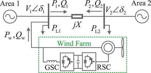
FIGURE 1. Two-area power system integrated with the DFIG-based wind farm.
2.1 Wind Farm Model
The DFIG model (Xiahou and Wu, 2018; Xiahou K. S. et al., 2020) can be expressed in the synchronous rotating d-q reference frame. The stator flux linkages of the DFIG are given as
and the rotor flux linkages of the DFIG are represented by
where ψsd and ψsq are the d-axis and q-axis components of the stator flux, respectively. ψrd and ψrq are the d-axis and q-axis components of rotor fluxes, respectively. Isd and Isq are d-axis and q-axis components of stator currents, respectively. Ird and Irq are the d-axis and q-axis components of rotor currents, respectively. Lls, Llr, and Lm are the stator leakage inductance, rotor leakage inductance, and mutual inductance, respectively. Ls = Lls + Lm is the stator self-inductance, and Lr = Llr + Lm is the rotor self-inductance.
The dynamics of stator flux linkages of the DFIG are expressed by
and the dynamics of rotor flux linkages are given by
where ωs, ωr, and ωslip = ωs − ωr are the synchronous speed, rotor speed, and slip speed, respectively. Vsd and Vsq are the d-axis and q-axis components of stator voltages, respectively; Vrd and Vrq are the d-axis and q-axis components of rotor voltages, respectively; and Rs and Rr are the stator and rotor resistances, respectively.
The stator active and reactive powers of the DFIG are calculated as
where Ps is the stator active power and Qs is the stator reactive power. The speed motion equation of the DFIG can be represented as
where Tm is the mechanical torque, Hw is the inertia constant, Dw is the damping factor, and Te is the electromagnetic torque given by
2.2 Power System Model
The two-area power system model integrated with the wind farm illustrated in Figure 1 is considered, which can be expressed by the swing equation (Kundur, 1994; Tobergte and Curtis, 2013; Xiahou et al., 2022)
where δ12 = δ1 − δ2 is the rotor angle deviation between Area 1 and Area 2 and δ1 and δ2 are the rotor angles of Area 1 and Area 2, respectively. ω12 = ω1 − ω2 is the generator speed deviation between Area 1 and Area 2, and ω1 and ω2 are the generator speed of Area 1 and Area 2, respectively. H1 and H2 are the equivalent inertia of Area 1 and Area 2, respectively. Pm1 and Pm2 are the mechanical power of Area 1 and Area 2, respectively. PL1 and PL2 are the load power of Area 1 and Area 2, respectively. V1 and V2 are the terminal voltage of Area 1 and Area 2, respectively.
The DFIG-based wind farm is connected to Area 1; thus, the two-area power system model with the wind farm becomes
where Pw is the active power of the wind farm. A supplementary reactive power controller is adopted to damp the inter-area oscillations of the power system. The reactive power Q1 of Area 1 can be expressed as
where Qw is the reactive power of the wind farm, Qc is the reactive power of the capacitive compensator and synchronous generator, and X is the impedance of the transmission line.
3 Perturbation Observer–Based Robust Nonlinear Damping Control
3.1 Nonlinear System Model for Damping Control
Taking the power angle δ2 = 0 as the reference value, it has δ12 = δ1. Thus, the two-area power system model becomes
From (15), the terminal voltage V1 of the Area 1 power system can be expressed as
Replacing V1 with (17) in (16), it has
The reactive power control loop of the DFIG can be approximated by a first-order model as
where
where ΔQw is the reactive power output caused by the damping controller and
where
3.2 Controller Design
Taking
where
Taking the control target y = x2 = ω12 as the output signal, the measurement equation is given as
The input–output linearization method is applied for the single-input-single-output (SISO) nonlinear system model (22)–(24). Differentiating the output variable y until the control signal u explicitly appears, which can be represented by
where the Lie derivations
Since the Lie derivative
The perturbation term ψ of the damping control system is introduced as
to represent the combined effects of nonlinearities, uncertainties, and external disturbances of the system, where the constant parameter b0 is to be tuned. Based on the definition of the perturbation term in Eq. 28, the system model (25) can be transformed as
The new state variable
with
With the feedback linearization control law
the nonlinear system Θ can be linearized exactly into the following linear system
where K is the feedback gain matrix which is to be designed.
However, the perturbation state ξ3 of control law (32) is unknown, which is almost impossible to be implemented. Thus, the perturbation observer is designed to estimate the system perturbation state. Based on Eq. 30, a perturbation observer
where
Based on the system state estimation
where the perturbation estimation
Based on the abovementioned analysis, the block diagram of the proposed perturbation observer–based robust nonlinear damping control scheme is illustrated in Figure 2. As seen, the PI-based dual-loop vector control scheme is adopted to control the RSC of the DFIG-based wind farm. The rotor currents Ird, Irq of the DFIG is regulated to their reference values
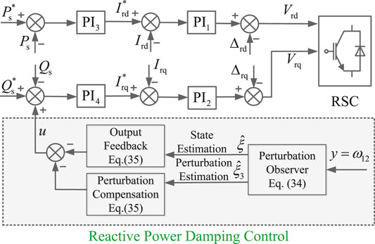
FIGURE 2. Schematic of the proposed perturbation observer-based RNDC scheme.
4 Simulation Studies
Simulation studies are undertaken on the detailed two-area four-machine power system with the wind farm illustrated in Figure 3 built in Simulink/Sim Power Systems.
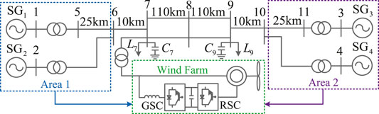
FIGURE 3. Configuration of the simulated power system.
The detailed parameters of the two-area four-machine power system are given in the study by Kundur, (1994). The rated power of Area 1 and Area 2 power is set as 1800 MW;, and the rated power of the DFIG-based wind farm is set as 180 MW; thus, the penetration level of the wind power of Area 1 reached 10%. The parameters of the DFIG-based wind farm are given as follows: rated voltage Vnom = 690 V, rated frequency fnom = 60 Hz, rated power Pnom = 2 MW, rated wind speed Vwnom = 11 m/s, stator leakage inductance Lls = 0.18 p. u., rotor leakage inductance Llr = 0.16 p. u., mutual inductance Lm = 2.9 p. u., stator resistance Rs = 0.023 p. u., and rotor resistance Rr = 0.016 p. u. The proposed RNDC scheme is compared with the classical damping control (CDC) (Miao et al., 2009) and sliding-mode control (SMC) (Liao et al., 2016) schemes under the conditions of three-phase-to-ground faults, parameter variations, and time delays.
4.1 Three-phase-to-ground Fault
In the first case, a three-phase-to-ground short-circuit fault is caused in the middle between Bus 7 and Bus 8 at t = 0.5 s, which means the fault location is 110 km away from the Area 1 power system. The simulation results of power angle deviation δ12, speed deviation ω12, active power P1 of Area 1, active power P2 of Area 2, active power Pw of wind farm, reactive power Qw of wind farm, rotor speed ωr of wind farm, and DC-link voltage Vdc of wind farm are given in Figure 4.
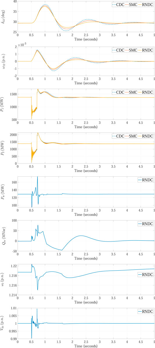
FIGURE 4. Simulation results obtained in the case where a three-phase-to-ground fault occurs in the middle of the transmission line.
As seen, after the three-phase-to-ground fault happens, the responses δ12 and ω12 of the two-area power system present low-frequency oscillations. All the three damping control schemes of the CDC, SMC, and RNDC can damp the inter-area oscillations, while the proposed RNDC scheme shows better damping performance than both the CDC and SMC. Meanwhile, the RNDC scheme adjusts the reactive power Qw of the wind farm to damp the oscillations, and the responses of active power Pw, reactive power Qw, rotor speed ωr, and DC-link voltage Vdc of the wind farm can quickly reach the stable states.
In addition, a three-phase-to-ground short-circuit fault is caused 20 km away from the Area 1 power system, and the simulation results are shown in Figure 5. Since the fault location is close to Bus 7, the responses of power angle deviation δ12, speed deviation ω12, active power P1 of Area 1, and active power P2 of Area 2 present much larger oscillations than the simulation results in Figure 4. According to the simulation results, the proposed RNDC scheme still shows better damping performance than both the CDC and SMC schemes, which verify the effectiveness of the RNDC scheme.
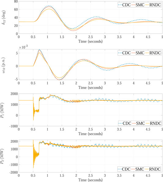
FIGURE 5. Simulation results obtained in the case where a three-phase-to-ground fault occurs close to the Area 1 power system.
4.2 Parameter Variations
The performance of the proposed RNDC scheme is further compared with that of the SMC scheme under the condition of parameter variations. In this case, the equivalent inertia H2 of Area 2 and the impedance X of transmission line are varied with +20% and −20% errors, respectively. Meanwhile, a three-phase-to-ground short-circuit fault is caused at the middle between Bus 7 and Bus 8 at t = 0.5 s, and the simulation results of the SMC and RNDC are illustrated in Figures 6A,B, respectively. As can be seen from the responses of δ12, ω12, P1, and P2, the parameter variations deteriorate the control performance of the SMC. This is due to the fact that the implementation of the SMC requires many model parameters of Area 1 and Area 2 power systems. Nevertheless, the implementation of the RNDC does not require any model parameters. The simulation results of the RNDC obtained with and without parameter variations are almost the same, which demonstrates the stronger robustness of the RNDC against parameter uncertainties than the SMC.

FIGURE 6. Simulation results of the (A) SMC and (B) RNDC obtained under parameter variations.
4.3 Time Delays
In this case, the proposed RNDC scheme is tested under the condition of time delay. A time delay of 50 ms is added to the measurement signal derived from the Area 2 power system, a three-phase-to-ground short-circuit fault is caused at the middle between Bus 7 and Bus 8 at t = 0.5 s, and the simulation results are shown in Figure 7.
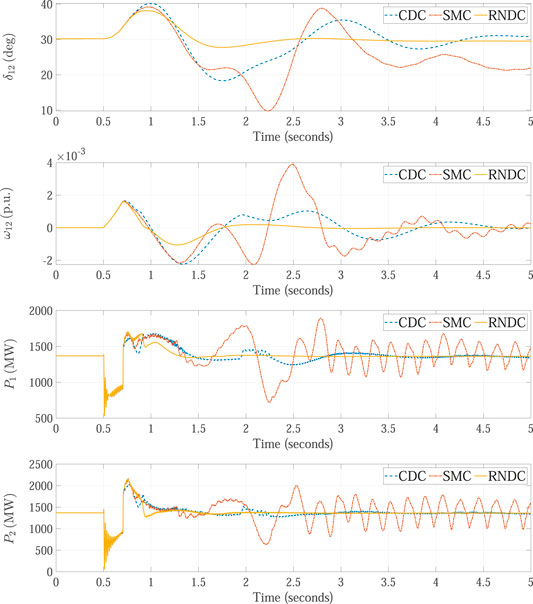
FIGURE 7. Simulation results obtained under the condition of time delay.
As observed from the responses of δ12, ω12, P1, and P2, the time delay of the measurement signal degrades the performance of the CDC, SMC, and RNDC schemes. Since the SMC scheme requires many measurement signals from Area 2 power systems, the SMC scheme presents large fluctuations, and the power systems is almost unstable. Both the CDC and RNDC can still damp the inter-area oscillations, and the RNDC shows much better control performance than the CDC, which reveals the strong adaption ability of the RNDC to time delays.
5 Conclusion
This study has proposed an RNDC scheme for DFIG-based wind farms to damp the inter-area oscillations of power systems. The RNDC scheme is implemented based on the perturbation observer and feedback linearization control method. Simulation studies are undertaken on a two-area power system model with 10% level penetration of the wind farm. According to the simulation results obtained under the conditions of three-phase-to-ground short-circuit faults, parameter variations, and time delays, conclusions can be drawn as follows.
First, the proposed RNDC scheme can damp the inter-area oscillations of power systems caused by three-phase-to-ground short-circuit faults, and it shows better damping performance than both the CDC scheme and SMC scheme. Meanwhile, the proposed RNDC scheme presents stronger robustness against parameter variations and better adaption ability to time delays. This is due to the fact that the RNDC scheme only requires one measurement signal and does not need any model parameters. In addition, the accurate perturbation estimation derived from the perturbation observer is applied to compensate the unknown dynamics of nonlinear systems in the RNDC scheme. Finally, with the perturbation compensation and output feedback control, the RNDC can realize the exact feedback linearization control of DFIG-based wind farms and effectively damp the inter-area oscillations of multi-area power systems.
Data Availability Statement
The original contributions presented in the study are included in the article/Supplementary Material; further inquiries can be directed to the corresponding author.
Author Contributions
BL: Investigation, methodology, software, and writing—original draft. SY: Supervision, data curation, and writing—review and editing. BY: Visualization and writing—review and editing. KF: Writing—review and editing.
Funding
This work was supported by the project of State Grid Jiangsu Electric Power Co., Ltd. (research and economic analysis of cluster control strategy for multi-client adjustable loads, No. J2021152).
Conflict of Interest
Authors BL, SY, BY, and KF were employed by Marketing Service Center, State Grid Jiangsu Electric Power Co., Ltd.
Publisher’s Note
All claims expressed in this article are solely those of the authors and do not necessarily represent those of their affiliated organizations, or those of the publisher, the editors, and the reviewers. Any product that may be evaluated in this article, or claim that may be made by its manufacturer, is not guaranteed or endorsed by the publisher.
References
Fan, L., Yin, H., and Miao, Z. (2011). On Active/reactive Power Modulation of Dfig-Based Wind Generation for Interarea Oscillation Damping. IEEE Trans. Energy Convers. 26, 513–521. doi:10.1109/tec.2010.2089985
Huang, H., and Chung, C. Y. (2012). Coordinated Damping Control Design for Dfig-Based Wind Generation Considering Power Output Variation. IEEE Trans. Power Syst. 27, 1916–1925. doi:10.1109/tpwrs.2012.2190110
Hughes, F. M., Anaya-Lara, O., Jenkins, N., and Strbac, G. (2006). A Power System Stabilizer for Dfig-Based Wind Generation. IEEE Trans. Power Syst. 21, 763–772. doi:10.1109/tpwrs.2006.873037
Kundur, P. (1994). Power System Stability and Control. New York, NY: Power System Stability and Control.
Kunjumuhammed, L. P., Pal, B. C., Oates, C., and Dyke, K. J. (2017). Electrical Oscillations in Wind Farm Systems: Analysis and Insight Based on Detailed Modeling. IEEE Trans. Sustain. Energy 7, 51–62.
Li, P., Xiong, L., Wu, F., Ma, M., and Wang, J. (2019). Sliding Mode Controller Based on Feedback Linearization for Damping of Sub-synchronous Control Interaction in Dfig-Based Wind Power Plants. Int. J. Electr. Power & Energy Syst. 107, 239–250. doi:10.1016/j.ijepes.2018.11.020
Liao, K., He, Z., Xu, Y., Chen, G., Dong, Z. Y., and Wong, K. P. (2016). A Sliding Mode Based Damping Control of Dfig for Interarea Power Oscillations. IEEE Trans. Sustain. Energy 8, 258–267.
Liao, K., Xu, Y., He, Z., and Dong, Z. Y. (2017). Second-order Sliding Mode Based P-Q Coordinated Modulation of Dfigs against Interarea Oscillations. IEEE Trans. Power Syst. 32, 4978–4980. doi:10.1109/tpwrs.2017.2667228
Liu, S., Zenelis, I., Li, Y., Wang, X., Li, Q., and Zhu, L. (2022). Markov Game for Securing Wide-Area Damping Control against False Data Injection Attacks. IEEE Syst. J. to be published.
Miao, Z., Fan, L., Osborn, D., and Yuvarajan, S. (2009). Control of Dfig-Based Wind Generation to Improve Interarea Oscillation Damping. IEEE Trans. Energy Convers. 24, 415–422. doi:10.1109/tec.2009.2015980
Mir, A. S., and Senroy, N. (2020). DFIG Damping Controller Design Using Robust CKF-Based Adaptive Dynamic Programming. IEEE Trans. Sustain. Energy 11, 839–850. doi:10.1109/tste.2019.2910262
Moness, M., and Moustafa, A. M. (2020). Real-time Switched Model Predictive Control for a Cyber-Physical Wind Turbine Emulator. IEEE Trans. Ind. Inf. 16, 3807–3817. doi:10.1109/tii.2019.2937549
Shi, X., Cao, Y., Shahidehpour, M., Li, Y., Wu, X., and Li, Z. (2020). Data-driven Wide-Area Model-free Adaptive Damping Control with Communication Delays for Wind Farm. IEEE Trans. Smart Grid 11, 5062–5071. doi:10.1109/tsg.2020.3001640
Singh, M., Allen, A. J., Muljadi, E., Gevorgian, V., Zhang, Y., and Santoso, S. (2014). Interarea Oscillation Damping Controls for Wind Power Plants. IEEE Trans. Sustain. Energy 6, 967–975.
Wei, C., Zhao, Y., Zheng, Y., Xie, L., and Smedley, K. M. (2022). Analysis and Design of a Nonisolated High Step-Down Converter with Coupled Inductor and Zvs Operation. IEEE Trans. Ind. Electron. 69, 9007–9018. doi:10.1109/tie.2021.3114721
Xiahou, K., Li, M. S., Liu, Y., and Wu, Q. H. (2018a). Sensor Fault Tolerance Enhancement of Dfig-Wts via Perturbation Observer-Based Dpc and Two-Stage Kalman Filters. IEEE Trans. Energy Convers. 33, 483–495. doi:10.1109/tec.2017.2771250
Xiahou, K., Lin, X., Liu, Y., and Wu, Q. H. (2018b). Robust Rotor-Current Sensorless Control of Doubly Fed Induction Generators. IEEE Trans. Energy Convers. 33, 897–899. doi:10.1109/tec.2018.2813089
Xiahou, K., Liu, Y., Wang, L., Li, M. S., and Wu, Q. H. (2020b). Switching Fault-Tolerant Control for Dfig-Based Wind Turbines with Rotor and Stator Current Sensor Faults. IEEE Access 7, 103390–103403.
Xiahou, K., Liu, Y., and Wu, Q. H. (2022). Decentralized Detection and Mitigation of Multiple False Data Injection Attacks in Multiarea Power Systems. IEEE J. Emerg. Sel. Top. Ind. Electron. 3, 101–112. doi:10.1109/jestie.2021.3112919
Xiahou, K. S., Liu, Y., Li, M. S., and Wu, Q. H. (2020a). Sensor Fault-Tolerant Control of Dfig Based Wind Energy Conversion Systems. Int. J. Electr. Power & Energy Syst. 117, 105563–105577. doi:10.1016/j.ijepes.2019.105563
Xiahou, K. S., Liu, Y., Zhang, L. L., Li, M. S., and Wu, Q. H. (2021). Robust Current Sensorless Control of Vsc-Based Mtdc Transmissions for Integrating Wind Farms. IEEE J. Emerg. Sel. Top. Power Electron. 9, 7383–7394. doi:10.1109/jestpe.2020.3004868
Xiahou, K. S., and Wu, Q. H. (2018). Fault-tolerant Control of Doubly-Fed Induction Generators under Voltage and Current Sensor Faults. Int. J. Electr. Power & Energy Syst. 98, 48–61. doi:10.1016/j.ijepes.2017.11.028
Xiao, D., AlAshery, M. K., and Wei, Q. (2022). Optimal Price-Maker Trading Strategy of Wind Power Producer Using Virtual Bidding. J. Mod. Power Syst. Clean Energy 10, 766–779. doi:10.35833/mpce.2020.000070
Xue, Z. Y., Xiahou, K. S., Li, M. S., Ji, T. Y., and Wu, Q. H. (2019). Diagnosis of Multiple Open-Circuit Switch Faults Based on Long Short-Term Memory Network for Dfig-Based Wind Turbine Systems. IEEE J. Emerg. Sel. Top. Power Electron. 8, 2600–2610.
Yao, W., Jiang, L., Wen, J., Wu, Q., and Cheng, S. (2015). Wide-area Damping Controller for Power System Interarea Oscillations: A Networked Predictive Control Approach. IEEE Trans. Contr. Syst. Technol. 23, 27–36. doi:10.1109/tcst.2014.2311852
Yao, W., Jiang, L., Wen, J., Wu, Q. H., and Cheng, S. (2013). Wide-area Damping Controller of Facts Devices for Inter-area Oscillations Considering Communication Time Delays. IEEE Trans. Power Syst. 29, 318–329.
Yao, W., Jiang, L., Wu, Q. H., Wen, J. Y., and Cheng, S. J. (2011). Delay-dependent Stability Analysis of the Power System with a Wide-Area Damping Controller Embedded. IEEE Trans. Power Syst. 26, 233–240. doi:10.1109/tpwrs.2010.2093031
Yogarathinam, A., and Chaudhuri, N. R. (2018). Wide-area Damping Control Using Multiple Dfig-Based Wind Farms under Stochastic Data Packet Dropouts. IEEE Trans. Smart Grid 9, 3383–3393. doi:10.1109/tsg.2016.2631448
Keywords: DFIG, wind farm, damping control, reactive power control, inter-area oscillations
Citation: Li B, Yang S, Yang B and Fang K (2022) Robust Nonlinear Control of DFIG-Based Wind Farms for Damping Inter-Area Oscillations of Power Systems. Front. Energy Res. 10:936580. doi: 10.3389/fenrg.2022.936580
Received: 05 May 2022; Accepted: 25 May 2022;
Published: 13 July 2022.
Edited by:
Dongliang Xiao, South China University of Technology, ChinaCopyright © 2022 Li, Yang, Yang and Fang. This is an open-access article distributed under the terms of the Creative Commons Attribution License (CC BY). The use, distribution or reproduction in other forums is permitted, provided the original author(s) and the copyright owner(s) are credited and that the original publication in this journal is cited, in accordance with accepted academic practice. No use, distribution or reproduction is permitted which does not comply with these terms.
*Correspondence: Shihai Yang, eXNoLnlvdW5nQDE2My5jb20=