 Yujie Wang1
 Shengshi Zhong
- 1School of International Education, Wuhan University of Technology, Wuhan, China
- 2School of Automation, Wuhan University of Technology, Wuhan Road Rover Intelligent Technology Co., Ltd., Wuhan, China
- 3Liuzhou Wuling Automobile Industry Co., Ltd., Liuzhou, China
The current pure electric vacuum vehicle is equipped with main and auxiliary motors, and the two motors work independently without affecting each other. The traditional auxiliary motor usually operates with constant power while the main motor is only responsible for the vehicle driving. The lack of cooperation between the two motors results in high energy consumption. Therefore, formulating a reasonable strategy for the two motors has a significant effect on the performance of the vacuum vehicle. This paper takes a pure electric vacuum vehicle as an example to propose an energy management strategy based on fuzzy control. First, for the working motor, a fuzzy controller is designed by taking the vehicle speed and acceleration as input and motor speed and torque as output. Therefore, the vacuum vehicle can automatically adjust the operating power of the cleaning system according to the real-time road conditions; the driving motor control strategy adopts a closed-loop control strategy that combines driver input and vehicle state parameter feedback based on considering the operating motor. Finally, the effectiveness of the strategy is verified by simulation. The results show that the energy-saving control strategy effectively reduces the power consumption per 100 km and increases the driving range, which is of great significance to the development and design of the vacuum vehicle.
1 Introduction
As the country pays more and more attention to environmental issues, the traditional working methods of road sanitation workers can no longer meet the current needs. As a road cleaning vehicle, the vacuum cleaner effectively relieves the pressure on sanitation and plays an important role in improving the environment. However, compared to the developed countries, domestic vacuum vehicles have some disadvantages, such as noise, and have more power consumption (Zhang, 2020). Different from the pure electric vehicle driven by dual motors (Ruan and Song, 2019; Wu et al., 2019; Wu and Zhang, 2021), for the research object of this article, the main motor is equipped to drive the car, and the auxiliary motor provides power for the bodywork system (Yang, 2016), so a reasonable strategy is developed for the two motors. It has a great effect on the working performance of the vacuum vehicle.
Lee (Lee et al., 2019), Wang (Wang et al., 2021), Kant (Kant et al., 2021) et al. have optimized the structure of the motor to make its performance more prominent, and the focus of this paper is mainly on the control strategy. The drive motor in this paper is similar to the traditional car, and the research strategies to reduce energy consumption mainly focus on the drive control strategy, the regenerative braking energy feedback strategy, and the power limiting strategy (Zhang, 2014). At the same time, different scholars have applied different control methods to achieve the ideal effect. Luo et al. select the corresponding drive mode to give appropriate torque compensation according to the driver’s operation intention and improves the power and economy of pure electric vehicles (Luo and Niu, 2020). Ye et al. use a fuzzy control method to determine the ratio of mechanical braking force and regenerative braking force according to different braking intensities to formulate energy recovery control strategies (Ye et al., 2021). Justo et al. proposed a control strategy to predict torque using the fuzzy model of the permanent magnet synchronous motor of an electric vehicle, and the control is simple (Justo et al., 2017). At the same time, the energy management strategy based on fuzzy rules can realize the power distribution of the power system by setting the logic threshold, thereby improving the economy of the vehicle (Guo et al., 2021).
The working motor is only used in some special vehicles, and scholars have not studied it much, Dong constructed a torque control model of the multi-motor power system of an electric sweeper based on a fuzzy control strategy (Dong, 2019). Wang et al. developed and validate an efficiency model for electronically commutated motor fan systems (Wang et al., 2020). Long established the mathematical model of the control relationship of the hydraulic motor tracking servo motor, and the PID parameter setting combined control algorithm is adopted (Long et al., 2018). Shao designed a digital throttle control scheme for the speed of the disc brush motor using a fuzzy control algorithm so that the speed of the disc brush can be adjusted automatically, but the power consumption is not taken into consideration (Shao, 2005).
In addition, the research on multi-motor systems mainly considers the torque distribution between motors (Zhai et al., 2016; Liu et al., 2019), which provides certain ideas for multi-motor power systems. However, in general, there are few studies on energy-saving strategies for multi-motor commercial vehicles with large energy consumption. In this paper, for a certain pure electric vacuum vehicle, comprehensively considering SOC, vehicle speed, operating conditions, etc. an energy-saving strategy for pure electric vacuum vehicle based on fuzzy control is established. The torque output of the two motors is controlled separately, and the Simulink-Cruise joint simulation model verifies the economics of the strategy.
2 Object Description
Pure electric vacuum vehicles use batteries as power sources to drive motors to realize the vehicle’s walking and operating functions. Therefore, they can be divided into two parts: the driving system and the working system. According to the needs of vacuum vehicles, they can be equipped with single or dual motors. The research object of this paper is a dual-motor arrangement type. The main motor (that is, the driving motor) drives the vacuum vehicle to travel, and the auxiliary motor (that is, the working motor) provides power for the working device. The block diagram is shown in Figure 1. The vehicle and motor parameters of the research vehicle are shown in Table 1.
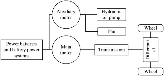
FIGURE 1. Block diagram of the main and auxiliary motor drive modes.
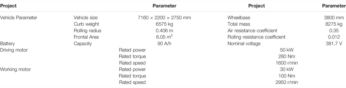
TABLE 1. Vehicle and motor parameters.
3 Model Establishment
3.1 Driving Model
During the driving process, the vehicle is affected by driving resistance, slope resistance, air resistance, and acceleration resistance. The required torque of the driving motor can be calculated by the dynamic equation of the driving system:
where,
3.2 Operating Model
In the operating system, the auxiliary motor mainly provides power for the fan and hydraulic components. The fan generates negative pressure and uses the force generated by the pressure to suck in garbage and dust. The hydraulic components are used to achieve the lifting and moving of the suction cup (Zhang, 2019). Since the power consumed by hydraulic components is much lower than the fan. It is ignored and only the power consumed by the fan is taken into consideration.
The needed torque of the working motor is:
Where,
3.3 Motor Model
The motor has complex structure and varies methods to establish its model with different complexity. In this case, the model is part of the vehicle, the performance of the components inside the motor is ignored. Thus, a simplified model with the torque and power characteristics is established (Tian et al., 2020). When the motor speed is less than the base speed, the motor works in the constant torque region, and the output power increases with the increase of the speed. When the motor speed is greater than the base speed, the motor works in the constant power area, and the output torque decreases as the speed increases. The motor’s operating characteristics are shown as the following equation.
Where,
The operating characteristic of the electrical motor is shown in Figure 2. The motor efficiency changes with the output speed and torque. The efficiency map of the driving motor is shown in Figure 3.
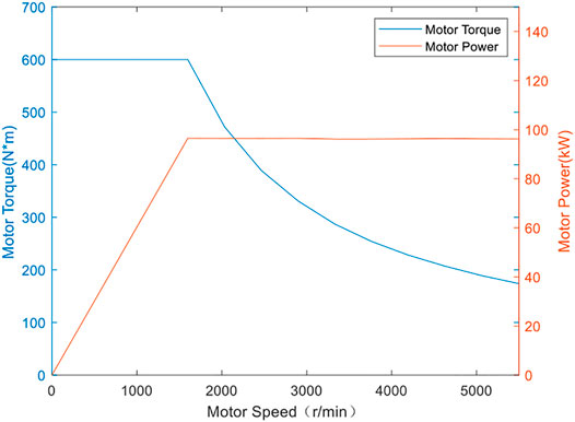
FIGURE 2. External characteristic diagram of the motor.
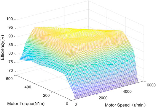
FIGURE 3. MAP diagram of motor efficiency.
4 Energy Management Strategy
4.1 Working Strategy
For traditional road vacuum vehicles, when the vacuum suction system is operating, it will clean the road garbage with constant power. Since the amount of garbage on the road does not always remain in a large state, the bodywork system of the vacuum vehicle always working at the same power will inevitably cause unnecessary energy loss (Li, 2020).
At the same time, during the operation of the electric vacuum vehicle, the relationship between the rotation speed, torque, and vehicle speed of the working motor is non-linear, which makes it impossible for us to establish an accurate mathematical model of the operation system. Therefore, a fuzzy controller is designed. It allows the vacuum vehicle to automatically adjust the operating power of the auxiliary motor according to the real-time road conditions, to achieve the goal of energy-saving.
During the operation, the driver adjusts the speed of the vehicle based on the garbage and dust on the road. At the same time, the cleaning efficiency decreases with the increase of the vehicle speed (Li et al., 2019), so when the driver recognizes that there is a lot of garbage on the road, he often reduces the vehicle speed and improves the cleaning degree. With the change of the vehicle speed, the rotation speed and torque of the working motor also varies. Therefore, this paper selects the vehicle speed v and acceleration a as the input, and the rotation speed of the working motor n, Torque q is the output, and a two-dimensional fuzzy controller is designed.
In the fuzzy control module, the fuzzy subsets, domains, and membership functions of input and output variables are defined. The explanation is as follows: The domain of the vehicle speed during the operation of the vacuum vehicle is set as (0, 20) km/h, and the fuzzy subset is taken as (S, MS, M, MB, B), which indicate that the vehicle speed is at low speed, low-to-medium speed, medium speed, medium-to-high-speed, and high-speed state respectively, the domain of the vacuum vehicle acceleration a is determined as (−1,1) m/s2, and its fuzzy subset is taken as: (NB, NS, ZO, PS, PB). It represents the acceleration is negatively large, negatively small, zero, positively small, and positively large. For output, the fuzzy domain of the operating motor speed n is determined to be (1500, 3500) r/min, use (S, MS, M, MB, B) to correspond to low speed, medium-low speed, medium speed, medium high speed, high-speed, The fuzzy domain of torque q is (50, 100) Nm, (S, MS, M, MB, B) indicates that the working motor is in the state of the small, medium-small, medium, medium-large, and large torque, respectively.
The membership function is often formulated based on experience. This article refers to some related literature (Cui et al., 2019; Luo et al., 2021). At the same time, according to the simulation analysis and theory, the membership function is adjusted to make it adapt to the energy control strategy. The membership degrees of input and output variables are shown in Figure 4:
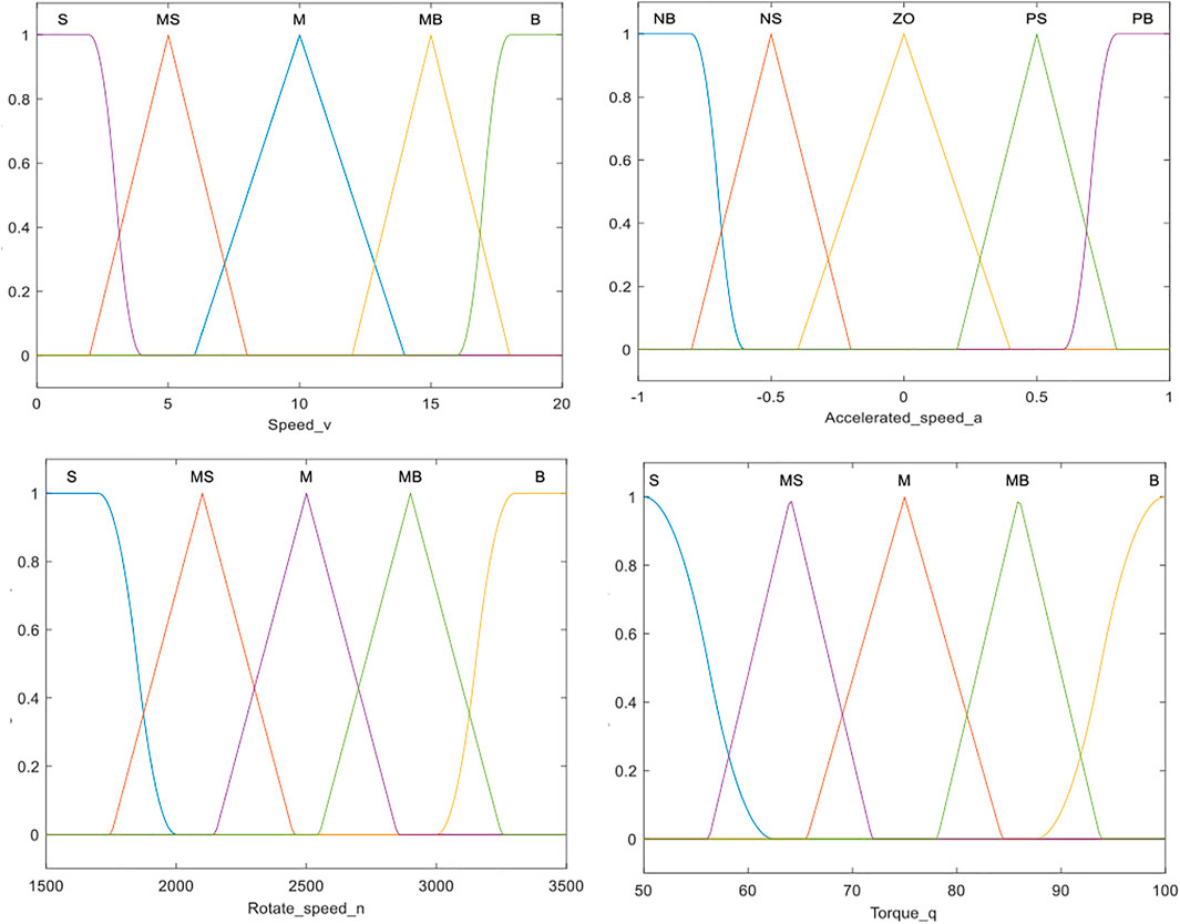
FIGURE 4. Membership function of input and output variables.
The corresponding fuzzy rules follow the following principles:
1) Under the premise of ensuring the cleaning efficiency, when the vehicle speed increases and the acceleration is relatively large, cleaning the road with the same garbage level requires greater power of the working motor, and the speed and torque of the working motor should be increased;
2) When the vehicle decelerates and the acceleration is small, it is less difficult to vacuum. To reduce energy consumption, the rotation speed and torque of the working motor should be reduced accordingly.
Based on the above rules, the fuzzy logic rules expressed by if-then sentences are established, and the inference surface of fuzzy control deduced is shown in Figure 5.
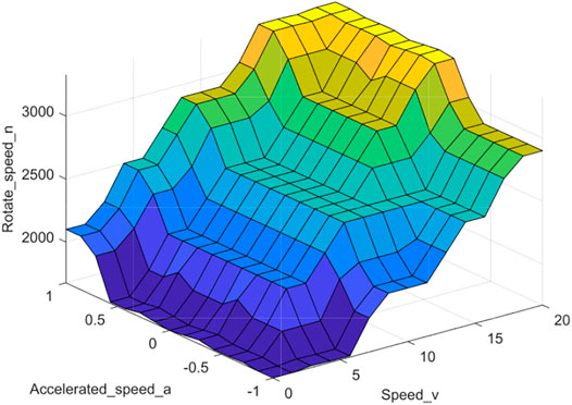
FIGURE 5. Fuzzy control reasoning surface.
4.2 Driving Strategy
The driving strategy should meets the drivers’ intention while maintain the motor works in the relatively high efficiency region. The proper driving strategy could extend the mileage of the electric vehicle (Asher et al., 2019). The drive motor torque control strategy proposed in this paper adopts a closed-loop control strategy that combines driver input and feedback of the vehicle state parameter. It does not only reflect the driver’s actual driving intentions but also considers the current vehicle system state. Figure 6 illustrates the torque control architecture. Among them, the output torque is defined as:
Where,
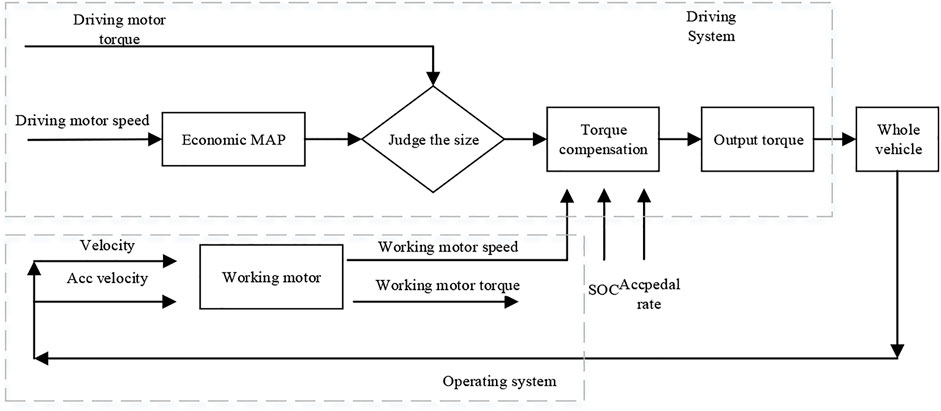
FIGURE 6. Torque control architecture.
4.2.1 Economic Torque MAP
During the operation of the vacuum vehicle, the driver obtains different required motor torques by controlling the position of the accelerator pedal. The operating characteristics of the motor can well meet the vehicle’s high torque at low speed and high power demand at high speed. To make the torque output corresponding to different accelerator pedal position more uniform, this paper will adopt the following interval division:
Where,
It can be seen from Figure 3 that the working efficiency is the highest when the motor speed
Where,

TABLE 2. The relationship between motor speed n and accelerator pedal opening S.
In this case, the corresponding vehicle speed is around 34 km/h-91 km/h. Assuming that the vehicle is driving at a constant speed on the road without any slope, ignoring the gradient resistance and acceleration resistance, the following formula can be obtained:
Where,
Define the torque load factor
Where,
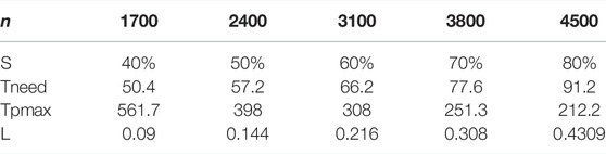
TABLE 3. Relationship between speed n and torque load factor L.
Using the curve for fitting, the relationship between the accelerator pedal position S and the torque load coefficient L is shown in Figure 7.
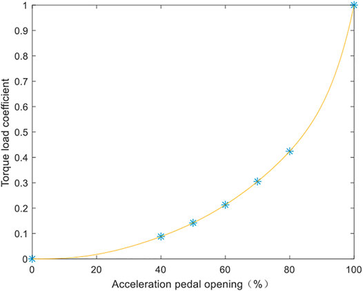
FIGURE 7. Relationship between accelerator pedal opening S and torque load coefficient L.
It can be seen from Figure 7, that when the accelerator pedal opening is small, the corresponding torque load coefficient is small and at the same time torque difference is small, this makes the maneuverability of the vehicle better. It is conducive to the long-term stable driving of the pure electric vacuum vehicle. When the accelerator pedal opening is increased, the torque difference increases and the motor demand torque response is more sensitive. The final economic torque MAP is shown in Figure 8.
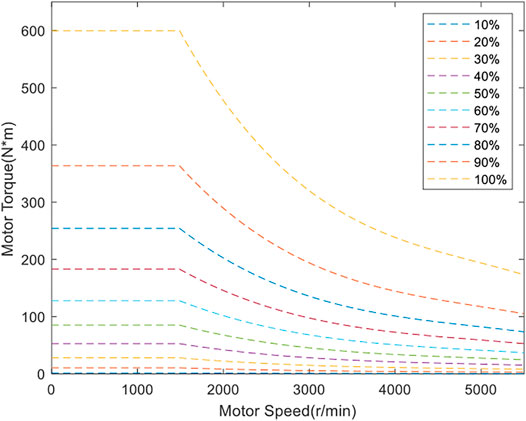
FIGURE 8. Economic torque MAP.
4.2.2 Compensation Torque
From Formula 5, when the economic torque found by the actual speed is less than the actual torque, a compensation torque is set, otherwise, the compensation torque is 0. In this paper, a compensation torque fuzzy controller is designed to obtain the value of ∆T.
The acceleration pedal change rate, operating motor speed, and battery SOC were selected as input variables to calculate the compensation torque increment by fuzzy reasoning.
The fuzzy subsets of SOC are defined as: (S, M, B), representing low, medium, and high respectively; The input range of operating motor speed is defined as 1500–3500 r/min, and (S, M, B) is used to correspond to low, medium and high-speed states. The input of acceleration pedal opening change rate is defined as
In the operation process, when the SOC is high, the operating motor speed is low, and the acceleration pedal opening change rate is large, it reflects that the driver has a high-power driving demand, and relatively high compensation torque is given. When the SOC is low, the operating motor speed is high, the acceleration pedal change rate is small, the driver’s power demand is relatively low and the compensation torque is small.
At the same time, considering that the sudden change of torque during the driving process of the vehicle will cause a greater impact, which will affect the ride comfort, it is necessary to consider the limit of the impact degree when determining the compensation torque increment (Wan, 2016), the expression of the impact degree:
Where,
From Formula 10, it can be obtained that the impact degree of the vehicle during driving is proportional to the rate of change of torque. The German shock degree standard stipulates j ≤ 10 m/s3, substituting the vehicle parameters and taking a 10% margin, the maximum value of the compensation torque
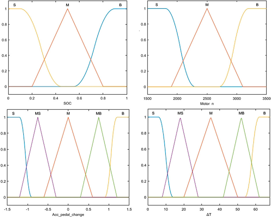
FIGURE 9. Membership function of input and output variables.
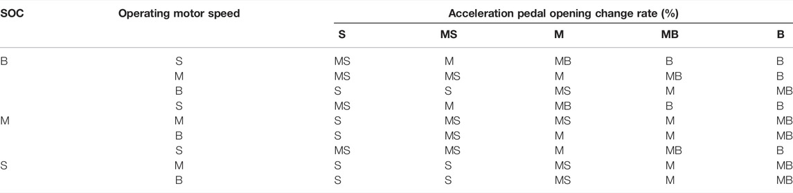
TABLE 4. Torque compensation fuzzy rules.
5 Joint Simulation and Simulation Result Analysis
This paper uses a pure electric vacuum vehicle as the research object to verify the effectiveness and superiority of the strategy. AVL Cruise software is used to build a vehicle model, and the energy-saving control model analyzed is built in MATLAB/Simulink software. In the simulation process, the performance of the original strategy, design strategy, and CRUISE strategy are compared. The original strategy refers to the strategy that the bodywork system works with the same power and there is no vehicle state feedback during driving. The CRUISE strategy refers to the strategy that comes with the CRUISE software and uses a linear method to adjust the power of the bodywork. The results were analyzed by co-simulation.
5.1 Establishment of Operating Conditions
Setting the condition is an important step in AVL CRUISE software simulation. The operating conditions of pure electric vacuum vehicles include working conditions and transition conditions, in which the working conditions account for more than 75% (Ma et al., 2018). Referring to the establishment process of NEDC, Tang et al. constructed a typical working condition of a sweeping vehicle (Tang, 2020). In this paper, part of the working conditions spectrum of CHTC is selected as the reference for transition conditions. Where, CHTC condition is the driving condition for Chinese automobiles used by the commercial vehicles with a total mass greater than 5500 kg. It includes the urban cycle (342 s), suburban cycle (988 s), and high-speed cycle (470 s). And the working conditions of vacuum vehicles in a certain area are combined to build the spectrum of the operating condition as shown in Figure 10.
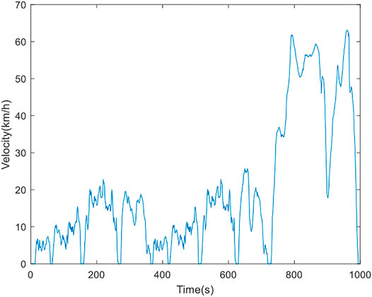
FIGURE 10. Road spectrum diagram of vacuum vehicle.
5.2 Simulation Analysis
In the case of a vacuum vehicle running in AVL CRUISE software, Figure 11 shows the comparison of SOC change trends under three strategies. The SOC decreases at a lower rate when energy-saving strategies are initiated. The original strategy has the minimum SOC at the end of the simulation.
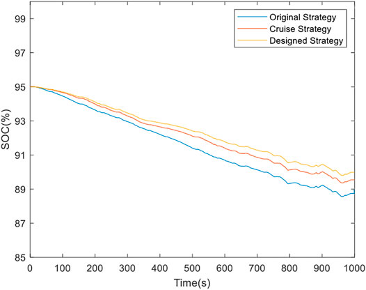
FIGURE 11. SOC trend changes.
Figure 12 shows the distribution of the working efficiency points of the driving motor. According to the simulation results, although the control strategy requires the motor to work in the optimal region, the driving motor must meet the requirements of high-speed transition, while the vacuum vehicle has been operating in the low-speed zone for a long time, most of the working points are in the range of 78–88%. The proportion of efficiency points in the high-efficiency area of motors with energy management strategies has increased compared with the original strategies.
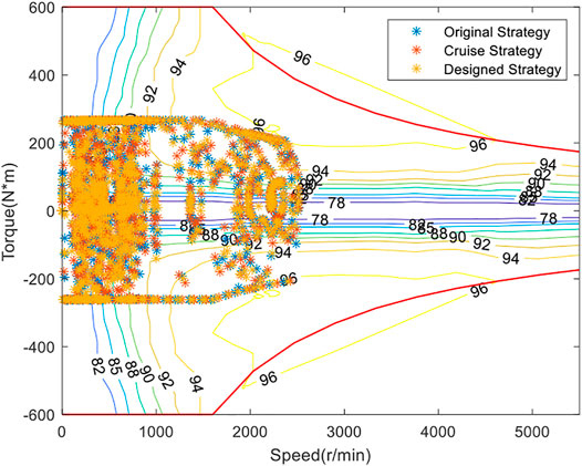
FIGURE 12. Distribution of working efficiency points of the drive motor.
Figure 13 is a comparison diagram of the power consumption of the working motor. It can be seen that the energy-saving strategy based on fuzzy control can automatically adjust the working power of the bodywork system. Compared with the other two strategies, the power consumption is smaller to achieve the effect of energy-saving. At the same time, it can be seen from the figure that the working motor of the vacuum vehicle is turned on under the working condition, and after the 750s, it is the transition condition, and the working motor does not work.
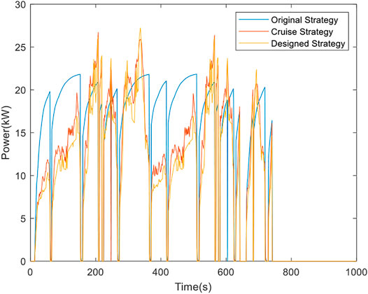
FIGURE 13. Comparison of power consumption of operating motor.
The energy consumption per 100 km and the driving range obtained in the AVL CRUISE with the three strategies are compared in Table 5.
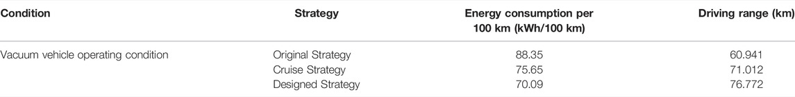
TABLE 5. Comparison of energy consumption per 100 km and driving range.
According to the simulation results under the constructed vacuum vehicle operating conditions, the energy consumption per 100 km of the vehicle is reduced from 88.35 kWh/100 km in the original strategy and 75.65 kWh/100 km in the Cruise strategy to 70.09 kWh/100 km in the design strategy. With a lower energy consumption, the charging and discharging time of the battery can be decreased, which means its life cycle can be extended.
Overall, the energy management strategy of the vacuum vehicle established in this paper reduces the power consumption per 100 km by 20.66%, and the driving range increases by 20.62%. In summary, the energy-saving strategy of electric vacuum vehicles based on fuzzy control proposed in this paper can effectively benefit the battery life cycle, reduce battery energy consumption and increase driving range.
6 Conclusion
To reduce the energy consumption of pure electric vacuum vehicles during operation, an energy management strategy based on fuzzy control is proposed. To verify the feasibility and superiority of the proposed control strategy, a vehicle dynamics model was established by AVL CRUISE and evaluated on the Simulink/CRUISE co-simulation platform. The conclusions of the study are as follows:
1) Based on the current road condition and vehicle status, the proposed fuzzy controller succeeds in managing the rotation speed and torque of the operating motor in a relatively high-efficiency region.
2) According to the simulation, compared with the original strategic control, the energy-saving strategy proposed in this paper reduces the economic performance index (power consumption per 100 km) by 20.66% and extends the driving range by 20.62%.
Since the energy consumption of the hydraulic system and mechanical lifting system is much lower than the motors, they are ignored. Therefore, the accuracy of the established model can be further improved by considering these factors in the next stage. Hence, the superiority of the proposed control strategy can be enhanced.
Data Availability Statement
The raw data supporting the conclusions of this article will be made available by the authors, without undue reservation.
Author Contributions
YW contributes to the writting of the manuscript, SZ provides the idea of this paper. YL and LZ help YW to finish this work.
Funding
This study was funded by the Innovative Research Team Development Program of Ministry of Education of China (IRT_17R83), and the 111 Project (B17034) of China.
Conflict of Interest
Author LZ was employed by the company Wuhan Road Rover Intelligent Technology Co., Ltd. Author SZ was employed by the company Liuzhou Wuling Automobile Industry Co., Ltd.
The remaining authors declare that the research was conducted in the absence of any commercial or financial relationships that could be construed as a potential conflict of interest.
Publisher’s Note
All claims expressed in this article are solely those of the authors and do not necessarily represent those of their affiliated organizations, or those of the publisher, the editors and the reviewers. Any product that may be evaluated in this article, or claim that may be made by its manufacturer, is not guaranteed or endorsed by the publisher.
References
Asher, Z. D., Patil, A. A., Wifvat, V. T., Frank, A., Samuelsen, S., Samuelsen, S., et al. (2019). Identification and Review of the Research Gaps Preventing a Realization of Optimal Energy Management Strategies in Vehicles. SAE Int. J. Alt. Power. 8 (2), 133–149. doi:10.4271/08-08-02-0009
Cui, P., Ding, A., Shen, Y., and Wang, Y.-X. (2019). “Hybrid Fuel Cell/Battery Power System Energy Management by Using Fuzzy Logic Control for Vehicle Application,” in 2019 IEEE 3rd International Conference on Green Energy and Applications (ICGEA), Taiyuan, China, 16-18 March 2019. doi:10.1109/ICGEA.2019.8880770
Dong, J. (2019). Research on Energy-Saving Strategy of Multi-Motor Power System of Electric Sweeper. Shanxi, China: Taiyuan University of Science and Technology. Available at: https://kns.cnki.net/KCMS/detail/detail.aspx?dbname=CMFD202101&filename=1019613483.nh.
Guo, C., Cao, D., Qiao, Y., Yang, Z., Chang, Z., Zhao, D., et al. (2021). Energy Management Strategy of Extended-Range Electric Bus Based on Model Predictive Control. SAE Int. J. Commer. Veh. 14 (2), 229–238. doi:10.4271/02-14-02-0018
Justo, J. J., Mwasilu, F., Kim, E.-K., Kim, J., Choi, H. H., and Jung, J.-W. (2017). Fuzzy Model Predictive Direct Torque Control of IPMSMs for Electric Vehicle Applications. IEEE/ASME Trans. Mechatron. 22 (4), 1542–1553. doi:10.1109/tmech.2017.2665670
Kant, K., Kirtley, J. L., Iyer, L. V., and Schlager, G. (2021). Finite Element Simulation-Based Design Optimization of Permanent Magnet Motors Considering Drive Cycle. SAE Int. J. Alt. Power. 7 (2), 157–165. doi:10.4271/14-10-02-0012
Lee, J. G., Yeo, H. K., Jung, H. K., Kim, T. K., and Ro, J. S. (2019). Electromagnetic and Thermal Analysis and Design of a Novel˗structured Surface˗mounted Permanent Magnet Motor with High˗power˗density. IET Electr. Power Appl. 13, 472–478. doi:10.1049/iet-epa.2018.5322
Li, J. H. (2020). Research on Energy-Saving Strategy of Pavement Garbage Identification and Top-Loading System of a Certain Type of Sweeper. Jilin, China: Jilin University. Available at: https://kns.cnki.net/KCMS/detail/detail.aspx?dbname=CMFD202002&filename=1020644024.nh.
Li, Y. J., Zhang, Y. P., Zhu, Y. D., and Huang, L. L. (2019). Analysis of the Influence of Working Parameters of Suction Sweepers on Cleaning Efficiency. Mech. Eng. Automation 48 (06), 19–20+23.
Liu, J., Zhong, H., Wang, L., and Chen, H. (2019). A Novel Torque Distribution Strategy for Distributed-Drive Electric Vehicle Considering Energy Saving and Brake Stability. SAE Technical Paper 2019-01-0334. doi:10.4271/2019-01-0334
Long, Z.-M., Guan, B.-J., Chen, S.-Y., Chen, G.-J., and Guo, S.-Q. (2018). “Modeling and Simulation of Hydraulic Motor Tracking Servo Motor Driving Load,” in 2018 International Conference on Smart Grid and Electrical Automation (ICSGEA), Changsha, China, 9-10 June 2018. doi:10.1109/icsgea.2018.00037
Luo, R., and Niu, Z. G. (2020). Drive Control Strategy of Pure Electric Vehicle Based on Pattern Recognition. Mech. Des. Manuf. 58, 37–41. doi:10.19356/j.cnki.1001-3997.2020.11.010
Luo, X., Deng, B., and Gan, W. (2021). Research on Fuzzy Control Strategy and Genetic Algorithm Optimization for Parallel Hybrid Electric Vehicle. J. Phys. Conf. Ser. 1986, 012106. doi:10.1088/1742-6596/1986/1/012106
Ma, C. S., Wang, K., and Ji, Q. X. (2018). Simulation Research on Power System of Pure Electric Sweeper Based on ADVISOR. Equip. Manuf. Technol. 2018 (09), 228–230.
Ruan, J., and Song, Q. (2019). A Novel Dual-Motor Two-Speed Direct Drive Battery Electric Vehicle Drivetrain. IEEE Access 7, 54330–54342. doi:10.1109/access.2019.2912994
Shao, Z. G. (2005). Design of Electric Control System of Sweeper and Research on Speed Control of Disc Brush. Nanjing, China: Nanjing University of Science and Technology. Available at: https://kns.cnki.net/KCMS/detail/detail.aspx?dbname=CMFD0506&filename=2005117818.nh.
Tang, Z. C. (2020). Establishment and Model Characterization of Typical Operating Conditions of Sweepers Based on Visual Perception. Jilin, China: Jilin University. Available at: https://kns.cnki.net/KCMS/detail/detail.aspx?dbname=CMFD202002&filename=1020644090.nh.
Tian, Z., Yang, B., Peng, D., Liu, Z., and Tan, G. (2020). Pre-Curve Braking Planning of Battery Electric Vehicle Based on Vehicle Infrastructure Cooperative System. Nanjing, China: WCX SAE World Congress Experience. SAE Technical Paper 2020-01-1643. doi:10.4271/2020-01-1643
Wan, H. T. (2016). Research on Drive Control Strategy of Pure Electric Vehicle. Beijing, China: Beijing Institute of Technology. Available at: https://kns.cnki.net/KCMS/detail/detail.aspx?dbname=CMFD201801&filename=1018812602.nh.
Wang, H. Y., Jiang, Z. L., Chao, P. B., Xiong, D. F., and Dai, Y. (2021). Analysis and Optimization of Stator Iron Loss of Permanent Magnet Synchronous Motor for Vehicles. Mot. Control Appl. 63 (09), 96–102+109.
Wang, Z., Han, Z., Ding, L., and Wang, G. (2020). Development of an Efficiency Model for Electronically Commutated Motor Fan Systems in Air Handling Units. Sci. Technol. Built Environ. 27, 329–340. doi:10.1080/23744731.2020.1797443
Wu, B., and Zhang, S. (2021). Energy Management Strategy for Dual-Motor Two-Speed Transmission Electric Vehicles Based on Dynamic Programming Algorithm Optimization. SAE Int. J. Elec. Veh. 10 (1), 19–31. doi:10.4271/14-10-01-0002
Wu, C.-Y., Liu, H.-J., Cheng, C.-Y., Hu, J.-S., and Tsai, M.-C. (2019). “Efficiency Regulation Algorithm for Dual-Motor Drive Electric Vehicles,” in 2019 IEEE Vehicle Power Propulsion Conference (VPPC), Hanoi, Vietnam, 14-17 Oct. 2019. doi:10.1109/vppc46532.2019.8952469
Yang, M. H. (2016). Research on Overall Design and Dust Collection System of Pure Electric Vacuum Sweeper. Shandong, China: Shandong University of Technology. Available at: https://kns.cnki.net/KCMS/detail/detail.aspx?dbname=CMFD201701&filename=1016230841.nh.
Ye, M., Tan, G., Lei, F., Chen, K., Feng, J., and Zhao, F. a. (2021). Research on Parallel Regenerative Braking Control of the Electric Commercial Vehicle Based on Fuzzy Logic. Wuhan, China: WCX SAE World Congress Experience. SAE Technical Paper 2021-01-0119. doi:10.4271/2021-01-0119
Zhai, L., Sun, T., and Wang, J. (2016). Electronic Stability Control Based on Motor Driving and Braking Torque Distribution for a Four In-Wheel Motor Drive Electric Vehicle. IEEE Trans. Veh. Technol. 65 (6), 4726–4739. doi:10.1109/tvt.2016.2526663
Zhang, D. B. (2020). Development Status and Future Trends of New Energy Sweepers in My Country. Automot. Pract. Technol. 45 (03), 27–29. doi:10.16638/j.cnki.1671-7988.2020.03.010
Zhang, P. Z. (2014). Research on Drive Control and Energy Management Strategy of Pure Electric Car. Jilin, China: Jilin University. Available at: https://kns.cnki.net/KCMS/detail/detail.aspx?dbname=CMFD201702&filename=1016123924.nh.
Zhang, T. J. (2019). Design and Simulation of Hydraulic System of Wet Road Sweeper. Shandong, China: Shandong University. Available at: https://kns.cnki.net/KCMS/detail/detail.aspx?dbname=CMFD201902&filename=1019077654.nh.
Keywords: pure electric vacuum vehicle, energy management strategy, fuzzy control, control strategy, energy-saving
Citation: Wang Y, Lei Y, Zhang L and Zhong S (2022) Research on Energy Management Strategy of Pure Electric Vacuum Vehicle Based on Fuzzy Control. Front. Energy Res. 10:935484. doi: 10.3389/fenrg.2022.935484
Received: 04 May 2022; Accepted: 24 May 2022;
Published: 15 June 2022.
Edited by:
Xue Lyu, University of Wisconsin-Madison, United StatesReviewed by:
Zhaowei Chen, Chongqing Jiaotong University, ChinaRongchao Jiang, Qingdao University, China
Copyright © 2022 Wang, Lei, Zhang and Zhong. This is an open-access article distributed under the terms of the Creative Commons Attribution License (CC BY). The use, distribution or reproduction in other forums is permitted, provided the original author(s) and the copyright owner(s) are credited and that the original publication in this journal is cited, in accordance with accepted academic practice. No use, distribution or reproduction is permitted which does not comply with these terms.
*Correspondence: Shengshi Zhong, emhvbmdzaGVuZ3NoaUB3dWxpbmcuY29tLmNu