- 1School of Electronics Engineering, VIT-AP University, Amaravati, India
- 2Department of Electrical and Electronics Engineering, GMR Institute of Technology, Srikakulam, India
- 3Department of Electrical and Electronics Engineering, Raghu Institute of Technology, Visakhapatnam, India
- 4School of Computer Science and Engineering, VIT-AP University, Amaravati, India
- 5Energy Processes Environment and Electrical Systems Unit, National Engineering School of Gabes, University of Gabes, Gabes, Tunisia
- 6Department of Electrical Engineering, College of Engineering, Northern Border University, Arar, Saudi Arabia
- 7Electrical Engineering Department, Prince Mohammad Bin Fahd University, Khobar, Saudi Arabia
- 8Department of Electrical Power and Machines, Faculty of Engineering, Alexandria University, Alexandria, Egypt
In this study, an investigation of different faults for a wind turbine–based doubly fed induction generator (DFIG) system is studied and the performance using a static compensator (STATCOM) is observed. The DFIG network is connected to a voltage source converter high-voltage dc link with a fault occurring near the wind generator network. The ride through capability of DFIG is promising with STATCOM using the proposed control strategy. The ac and dc voltage and torque oscillations are damped effectively, and improved power flow is observed. The low voltage AC grid fault occurs for an HVDC transmission, and the DFIG performance without and with STATCOM is compared, where the DFIG converter control schemes are developed using the proposed improved field-oriented control (IFOC) method. In this, the reference rotor flux value alters to a new synchronous speed value or a slighter value or a standstill depending on the stator voltage dip due to grid disturbance. This speed variation leads to introducing rotor current at that new rotor slip frequency as there is a change in the rotor speed because of the fault, which further decreases the stator flux dc component. Hence, this dc-offset constituent in the stator flux is alleviated and decays rapidly in scheming the divergence of the speed of the rotor to a new orientation speed with decay in the rotor flux. This operation is done in the inner control scheme of the rotor converter, which is quicker in response to the faults. Apart from this, the stator’s real and reactive power also changes accordingly based on the lookup table mechanism–based closed-loop control action of the pulse generator, and this power change is done in the outer loop. The analysis for DFIG and HVDC operation is verified under different faults without and with STATCOM.
1 Introduction
The off-shore DFIG-based WECS are mostly connected through a voltage source converter (VSC)-based high-voltage dc link (HVDC) system due to technically easy transmission of power and economic feasibility (Bozhko et al., 2008; De-Prada-Gil et al., 2015). However, such an HVDC wind energy conversion system (WECS) also needs to follow the grid code for better fault ride-through capability (Gorenstein Dedecca et al., 2018). Few studies describe on/off-shore VSC-HVDC WECS with different grid side disturbances (Giddani et al., 2010; Nanou et al., 2015). Recently, more researchers (Wu et al., 2014; Korompili et al., 2016) are looking for VSC-HVDC for the offshore side due to better wind flows and abundant sea-space availability. Based on the study by Korompili et al. (2016), there is a very great challenge faced by the DFIG-HVDC system to maintain the grid synchronization and no overvoltage at the dc link at DFIG converter terminals or HVDC terminals and also to have better active power flow under the faults.
Many authors (Wu et al., 2014; Kumar and Ravikumar, 2016; Kumar and Ravikumar, 2017) discussed self-regulating real and reactive power control from sending-end to receiving-end stations. The role of reactive power flow control helps in improving the voltage profile when grid disturbances are taking place. The performance of DFIG varies with different types of faults like symmetrical and asymmetrical faults (Ananth and Nagesh Kumar, 2016). Different control schemes are used to overcome these faults to have a better ride through. The same control strategy may not be effective for both faults but is promising to one fault and little compromising for the other. Few authors used choppers and different energy storage devices for the DFIG system at the converter terminals to overcome surge voltage inrushes toward rotor terminals and converters (Arman et al., 2017). Some others used different FACTS devices like the STATCOM, dynamic voltage restorer, and UPFC and also used fault current limiters to improve the transient reaction of the DFIG–HVDC hybrid system (Priti and Kumar, 2016).
Since external sources like FACTS and batteries are cost-effective but work efficiently for any type of fault. Different topologies like nine-switch converters are also used in the literature to improve FRT under different grid faults. The performance with a weak HVDC grid is different from a strong grid system, and the overcoming technique with a weak grid has been explained in a few studies (Leyla and Marinescu, 2015; Khazaei et al., 2018). Few control schemes are also developed to compensate for surge currents reaching into the DFIG rotor terminals (Ahmed et al., 2014). The VSC HVDC with wind energy conversion system including the DFIG generator system has been studied by many authors (Madariaga et al., 2013; Erlich et al., 2014; Abdou et al., 2015; Ashrafi Niaki et al., 2015; Moawwad et al., 2016; Nanou and Papathanassiou, 2016; Tang et al., 2016; Castro and Acha., 2018; Ebner et al., 2018). Fault recovery improvement for the HVDC-DFIG system using STATCOM with an adaptive modulation algorithm is presented in the study by Tang et al. (2016), and the performance is compared with different controllers under symmetrical and single-phase fault analysis. Frequency modulation analysis to improve fault ride-through (FRT) has been described in the study by Nanou and Papathanassiou (2016), and the technique was compared with other control schemes like inertia and droop. The controlled droop method for VSC-HVDC for different faults was studied in the work by Erlich et al. (2014). Similarly, fault-tolerant (Madariaga et al., 2013; Abdou et al., 2015; Moawwad et al., 2016; Castro and Acha., 2018; Ebner et al., 2018) and detection (Ashrafi Niaki et al., 2015)-based analyses are also studied to control the voltage and frequency swings, current surge mitigation, and sensitive DFIG system protection. In the same way, the authors in this study also try to improve the DFIG performance for a conventional simple HVDC grid system during different types of faults using the proposed improved field-oriented control (IFOC) method. Here, the rotor angular speed and the rotor winding actual and reactive power flow change with the rotor side converter (RSC) control with the proposed IFOC scheme are considered.
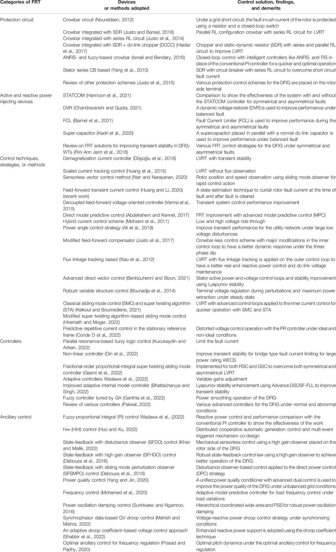
The disturbance analysis with analytical expressions was provided in the studies by Liang et al. (2010), Daoud et al. (2016), Amin et al. (2017), V. Pavan Kumar and Bhimasingu (2017), and Ananth (2018). The PI controller and tuning of it and the Bode plot-based analysis were discussed in the studies by Boubzizi et al. (2018) and Hu et al. (2020). Recent techniques have been developed to overcome balanced and unbalanced faults without allowing decomposition into positive and negative components, and the work was found to be more effective as discussed in Table 1 (Yang et al., 2010; Mohseni et al., 2011; Noureldeen, 2012; Xiao et al., 2012; Bounadja et al., 2014; Justo et al., 2014; Huang et al., 2015; Justo et al., 2015; Varma et al., 2015; Debouza et al., 2016; Ismail and Bendary, 2016; Abdelrahem and Kennel, 2017; Haidar et al., 2017; Justo et al., 2017; Debouza et al., 2018; Döşoğlu et al., 2018; Justo and Bansal, 2018; Rini Ann Jerin et al., 2018; Ali et al., 2019; Huang and Li, 2020; Kadri et al., 2020; Nair and Narayanan, 2020; Yang and Jin, 2020; Baimel et al., 2021; Benbouhenni and Bizon, 2021; Chandravanshi and Gupta, 2021; Hannoon et al., 2021; Kelkoul and Boumediene, 2021; Wadawa et al., 2022; Bhattacharyya and Singh, 2022; Wadawa et al., 2022; Conde D et al., 2022; Din et al., 2022; Ganthia et al., 2022; Gasmi et al., 2022; Hiremath and Moger, 2022; Huo and Xu, 2022; Khan and Mallik, 2022; Kucukaydin and Arikan, 2022; Paliwal, 2022). Still, these methods are unable to completely damp out pulsations in the torque or regain normal value even under the fault. Among all the methods developed for the DFIG, the demagnetization-based technique has less sensitivity to grid faults as this method is based on the natural flux decomposition. Still, generator stator parameter dependency is a drawback for this method, which increases the complexity of the control scheme. To overcome this, the virtual resistance method and arbitrary phase-locked loop changing–based sub-control are added for the demagnetization control methods. The advanced controllers and control strategies help in limiting the current under faults, which is improved when using fast-acting control techniques like stator-current-feed forward control, current reversely tracking control, higher-order sliding mode control–based demagnetization control, improved flux magnitude and angle control, and feed-forward current references control.
The contribution of the work includes 1) electromechanical energy conservation during grid disturbances, 2) effective functionality during and after the fault, and thus overall stability enhancement, 3) nearly consistent speed is observed even for a large grid voltage dip or rise as these will quickly increase or decrease the rotor speed beyond the safe limit, 4) damp torque and power oscillations and ability to retain its original value even when the fault is still prevailing and, hence, reliability and sustainability enhancement, 5) suitable for any grid disturbances, 6) limits surge inrush currents at the fault occurring or clearing instances, and 7) smoothens DFIG operation under any transient conditions.
In Section 2, the configuration of DFIG-based back-to-back converters for a grid-tied test-bed system is described. In Section 3, the dynamics of DFIG under grid disturbances are analyzed mathematically. In Section 4, the control circuit based on the proposed IFOC technique is discussed. Section 5 explains the simulation results with and without the STATCOM for an HVDC grid-connected system and a comparison of proposed and earlier works for low and high voltage faults in the MATLAB environment. The conclusion of the work is given in Section 6. Later, Appendix and references are given.
2 Configuration of the System
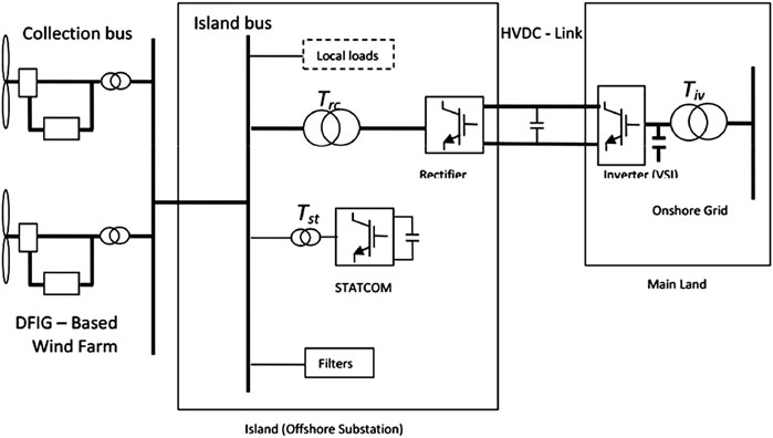
The overview of the wind energy conversion system (WECS) for an HVDC-based grid-connected system considered in this study is shown in Figure 1. The WECS contains a wind generator-turbine system and its output is connected to an HVDC grid bus bar. The HVDC is a piece of voltage source converter (VSC) technology with back-to-back converters. The converters for HVDC are conventional controller-based as in the study by Guo et al. (2017). With the proposed control strategy for DFIG, how the system performs during and after the faults is analyzed in this study. The mathematical modeling and converter design are described in the next two sections to overcome the faults of an HVDC-based grid-connected system.
3 Dynamics of Doubly Fed Induction Generator During Normal and Abnormal Grid Conditions
The basic relations of the DFIG under typical scenarios with no disturbance from the grid are used as given in the studies by Amin et al. (2017) and V. Pavan Kumar and Bhimasingu (2017). However, the grid voltage is often reduced due to external conditions like large load changes and transmission line faults. Thus, the behavior of DFIG analysis is important under grid voltage sag or swell. The DFIG stator and rotor winding voltages as a function of current and flux factor are stated as follows (Ananth and Nagesh Kumar, 2016; Ananth, 2018):
Also, both the windings’ flux linkage in terms of currents is as follows:
The dynamic rotor current in two quadrant frames can be expressed using the Eqs 2a, 2b, 6c, 6d, where
From the study of the DFIG, we know that the stator q-axis component is zero (Liang et al., 2010; Ananth, 2018) and the d-axis component is equal to the main stator flux under normal conditions. So, the Eqs 3a, 3b are rewritten as in Eqs 4a, 4b.
It is understandable from Eqs 4a, 4b that the rotor d and q axis currents are dependent on rotor resistance
3.1 Steady-State Operation of Doubly Fed Induction Generator System
The stator flux ψs can be written in terms of stator voltage Vs as Eq. 5. The synchronous angular speed is (ωs), stator reactance and the rotor reactance (Xs and Xr), angular slip frequency (ωslip), and stator and rotor inductance (Ls and Lr). The stator d and q axis and the rotor d and q axis voltages (Vds, Vqs, Vdr and Vqr) are represented in Eqs 6a–6e. The equations give relation in terms of d- and q-axis flux components (Ψds, Ψqs, Ψdr and Ψqr) and stator and rotor currents (ids, iqs, idr and iqr) (Ananth, 2018). Here, P represents “d/dt.”
Stator terminal voltage in terms of the stator flux component is as follows:
The DFIG flux components were described in the study by Liang et al. (2010) as a function of its current and are represented in Eqs 7a–7d.
where Lm is the mutual inductance of DFIG between the stator and rotor windings. Here,
Using Eqs 7a, 7b, the stator d and q axis currents can be represented in stator flux and rotor current terms, and we get Eqs 7e, 7f.
Now using Eqs 7c, 7e, the rotor flux in terms of rotor current is shown in Eqs 8a, 8b.
where
With the use of Eqs 6d, 8a, 8b, the rotor voltage as a function of rotor currents is as follows:
Eqs 9a, 9b define the relationship between rotor d and q axis voltages and currents. The currents are cross-coupled with the voltage parameters, which means that the d-axis voltage depends on both d and q axis rotor currents and, similarly, the q-axis voltage also depends on both d and q axis rotor currents. Now again, the stator d and q axis currents in Eqs 7e, 7f and also with the help of Eq. 6e in terms of stator voltage and rotor two-axis current variables are as follows:
Now using the above equations with stator currents from Eqs 7e–10b, the rotor currents can be defined in terms of stator and rotor voltages as shown in Eq. 11a with“‘s” as rotor slip.
The square of the sum of d and q rotor current is equal to the magnitude of the square of rotor current as follows:
The stator real and reactive powers can be represented as follows:
Using Eqs 12a, 12b, the rotor d and q axis reference currents in terms of stator real and reactive powers is shown in Eq. 13.
Representing Eq. 13 in Eq. 11b, the stator powers in terms of rotor current are given by Eq 14a.
Solving and simplifying Eq. 12a,we get Eq. 12b as follows:
It is in the form of a circle
Here, the tuning of the PI controller plays a vital role in the exact control of rotor voltages and the PWM pulse generation action. The control scheme using transfer function analysis and closed-loop control scheme with open-loop Bode plot analysis is discussed in Sections 3.3, 4.3. Furthermore, the reference real and reactive rotor current determinations are also important factors. Hence, based on these equations, the RSC control scheme is designed, which plays a very important role in DFIG operation and behavior. The electromagnetic torque in Eq. 14b is simplified and rewritten as given in Eq. 16.
Eq. 16 explains that the electromagnetic torque (EMT) of DFIG depends on its winding voltages and machine passive parameters. It is realized from this equation that the stator voltage is quadratic and also depends on slip speed. Hence, if grid voltage decreases due to any reason like grid fault, stator voltage decreases. This sudden decrease in stator voltage leads to oscillations in EMT and decreases to a small value accordingly. Due to these, the speed of the DFIG rotor increases to balance the equation as the square of the slip term is in the denominator. Hence, proper control action is required to make the EMT decrease with oscillations and the speed of the rotor be within limits with the help of the proposed RSC control scheme. So, EMT exact control can be done as follows. Eqs 10a, 10b, 11a can be modified as a function of EMT and stator reactive power as per Eqs 17, 18.
Hence, from the two Eqs 17, 18, the rotor currents can be controlled with exact control, or knowledge of stator real and reactive powers is possible. The rating of DFIG converters is small and is about 30% of the generator ratings. So, along with RSC, the GSC control scheme also helps in improving the performance of DFIG during steady-state and transient operations. If dc voltage is maintained across the capacitor, RSC performance will get improved. Also, reactive power controlling will be improved with the proper design of DFIG. For this, knowledge of stator and grid side parameters and variables is necessary.
3.2 Dynamic Operation of Doubly Fed Induction Generator
The dynamic analysis for flux and power flows of DFIG is described here. Eqs 19a, 19b with base angular speed (ωb) can be rewritten for differential stator flux values as follows:
The two axis stator flux will become the following:
The term P here refers to differentiation with respect to time. Using Eqs 20a, 20b in Eqs 19a, 19b, we get the following:
From Eq. 12a, the stator and rotor differential real and reactive powers are given by the following:
From Eqs 22a, 22b, it is observed that a q-axis change in rotor current can control the change in the stator real power, and similarly, with rotor d axis current change, stator reactive power can be controlled. With the change in stator voltage, the real and reactive powers will get affected. Here, the effect on reactive power will be high and will have oscillations as Eq. 22b is like a quadratic equation with stator voltage magnitude. Similarly, rotor power will also change with stator power. Based on these equations, control strategies are developed. From Eqs 4a, 4b, it is observed that the dynamics of rotor d and q axis currents are not entirely independent but depend on the model parameters, especially rotor resistance and stator and magnetizing inductance. For instance, in the d-axis rotor current equation in Eq. 4a, there is a coupling term
3.3 Improved FOC Method
Using the basic Eqs 6c, 6d of the DFIG, the rotor voltages can also be written as follows:
This rotor d-axis voltage Eq. 23a is rewritten as a function of rotor flux given in Eqs 7c, 7d) and transient synchronous speed as described in Eq. 23b. Here,
The term
The synchronous speed will change
The dynamic d- and q-axis currents can be rewritten using the Eqs 26a, 26b as follows:
The difference in the reference to the actual rotor current vector is controlled to maintain a zero equilibrium state using a well-tuned PI controller, done using the pole-placement technique (which is not within the scope of this study). The rotor reference voltages in Eqs 28a, 28b are the reference voltages to the PWM pulse generator developed from the above equations. It can be observed that it has both direct and cross-coupled parameters.
Based on the above Eqs 29a, 29b with the PI controller, the rotor and grid side converter control schemes are developed and are described in the next section.
4 Design of RSC, GSC, and STATCOM to Overcome Low Voltage Faults for Grid-Connected HVDC System
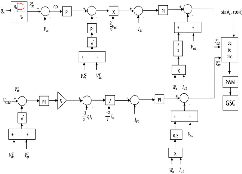
In general, the FOC technique for the DFIG control schemes is designed in a synchronously rotating frame to obtain an independent real and reactive power flow to maintain stability because of these transients. Figure 2 shows the block diagram of the GSC controller. Under normal operation, the reactive power from the stator winding will be very less, and so the maximum power is injected into the grid. The GSC control scheme will help in controlling the power flow between the DFIG and the grid. The coordination between the real and reactive power flows from the DFIG to the grid is controlled using a characteristic lookup table and is to control and maintain the setup reference value with the help of GSC outer loop PI control. The total mechanism is quick and effective during abnormal/normal grid conditions.
4.1 Design of the RSC and GSC Controllers
Considering the grid reactive power necessity and using the lookup table scheme as defined by Eq. 9b, optimal reference stator power is estimated and retained using the PI tuned controller, and its output is a reference current which is to be maintained so that dynamic change in current during abnormal situations must not lead to instability. The square of the difference in the reference to the actual dc capacitor voltage between both the converters is regulated using another PI controller.
The grid voltage or stator voltage is generally required to stay constant without fluctuations. This grid side voltage is kept constant using RMS-based stator/grid side voltage. The reference value is
4.2 Modeling of the STATCOM and Its Capacitor
The STATCOM reactance is X and the instant voltage value is K, reference bus voltage is E which is before the offshore HVDC grid, and d and q axis STATCOM voltages are Vd and Vq. The current to voltage parameters are identified using the transfer function model. Here, reference real and reactive powers at the grid bus and the STATCOM impedance and its bus parameters are inputs. The d- and q-axis injected STATCOM current is given by the following:
The STATCOM injecting current or absorbing current flow direction is based on the cumulative sign of the differential current vector as in Eq. 30 with the positive as injecting and the negative as absorbing reactive current. The change in the current flow in the STATCOM makes the dc-link voltage in the capacitor change according to Eq. 31.
The STATCOM power rating can be described analytically using the equations as follows:
The dynamic current flow Eqs 30a, 30b are simplified and written as follows:
4.3 Controller Design of Inner Loop Control for the Grid-Connected DFIG
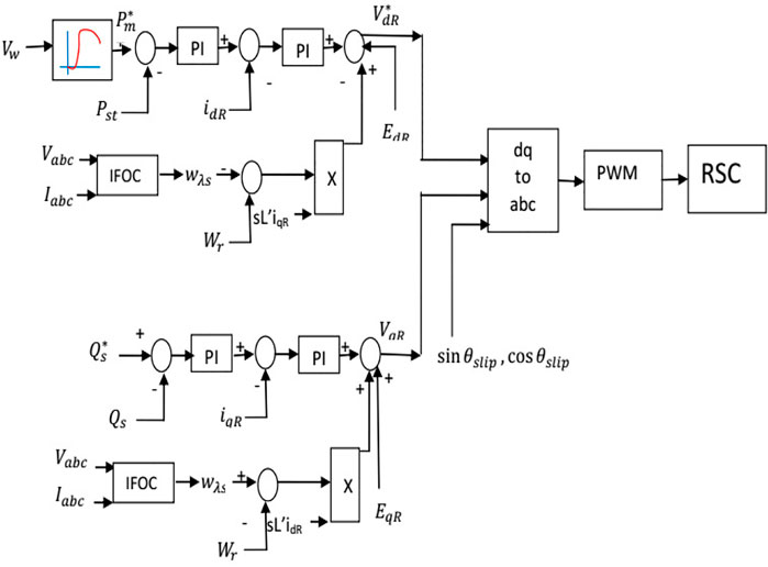
The closed-loop control for the DFIG rotor side controller representation is shown in Figure 4. The PI controller for the reference voltage control block diagram is GPI(s), the offset switching frequency of the RSC converter is (Gsw(s)), the DFIG grid-connected system plant model is represented as GDFIG (s), and the plant model is Av(s) (Boubzizi et al., 2018). The current PI controller is given by the Eq. 34a with‘s' as the Laplace parameter and current proportionality (Kpi), and the current integral constant (Kii) is shown in Eq. 34a (Hu et al., 2020)
The offset RSC converter switching block (GSW(s)) is a relay block that operates based on the reference
The DFIG standard transfer function model is considered to be a standard second-order function with natural undamped frequency
The rotor voltage gain
The DFIG RSC terminal voltage (V2) with initial voltage v20, disturbance voltage (VDFIG_R), output limited transfer function (Golimit(s)), and DFIG output transfer function (GoDFIG) is given by the transfer function Eq. 36a.
The internal transfer functions for Eq. 36a are defined and shown in Eqs 36b–Eqs 36d as follows:
The change or error in the DFIG rotor side terminal voltage is given by the difference between reference and actual rotor terminal voltage, as shown by Eq. 37. Here, the error in the DFIG rotor terminal voltage to zero is the objective.
The final output DFIG rotor terminal voltage is represented in the form of a transfer function (Gov(s)) in terms of a controller transfer function, DFIG rotor terminal transfer function, and the rotor voltage gain as depicted by Eq. 38.
The ratio of integral-to-proportional gain constants with a frequency of operation from 5 to 150 Hz is given by Eq. 39. The final output voltage transfer function is controlled to 1 p.u. value as given by Eq. 40.
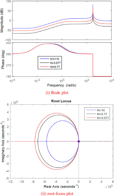
From Eqs 38, 40, the open-loop output DFIG rotor voltage transfer function based Bode plot and Root-Locus plots are shown for different integral constants in Figures 5i,ii with plot parameters being shown in Table 2. With the increase in the Kii, the phase margin is moving away from −180° and the gain margin is decreasing considerably; thereby, the stability margin is decreasing. The normal values of Kpp and Kii are 1.22e-3 and 0.77.
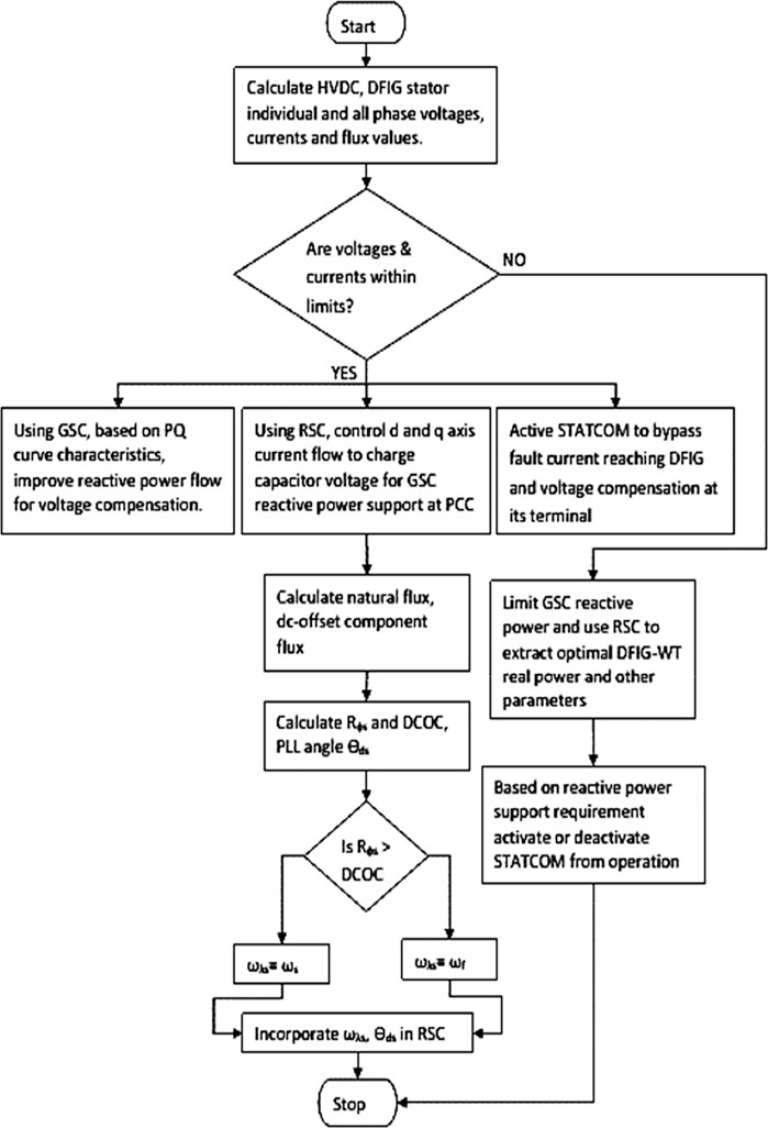
The assumption considered here is that the terminal voltage at the sending end is assumed as constant. To control these two, the stator synchronous speed reference has to be decreased based on the flux decay which is described using the flowchart in Figure 6. Similarly, when voltage increased due to load changes or grid disturbances, this new angular speed ωλs value has to be increased accordingly. So, the dc offset flux components are controlled by rapid changes like decay during fault and an increase during high voltage fault. Thereby, rotor surge currents are eliminated entering into the rotor windings and, consequently, torque oscillations are damped effectively, and rotor voltage and current profile can be improved.
5 Simulation Results and Analysis
The DFIG-based VSC-HVDC system for the test system shown in Figure 1 is examined under different cases with various types of faults. The performance is compared with the proposed DFIG control scheme without and with the STATCOM controller. The IFOC method is considered for a ten-generator–equivalent DFIG system as a single unit connected to an HVDC grid to improve the voltage and current profile of the DFIG as well as the HVDC grid and ensure further improvement with the application of a STATCOM. The major objective of the study is stable torque, maintaining nearly constant rotor speed, and flux control.
Here, a double line to ground fault having a healthy phase being C- phase occurred near the sending end side of HVDC, where DFIG-based wind farms are connected. Due to a very short circuit fault, the grid voltage reduces to nearly 0.1 pu volts in that faulty phase. The DFIG parameters like stator, rotor, and injecting grid side voltage and current are checked. Also, DFIG converter dc capacitor voltage, torque, and speed are checked for DFIG WECS. The DFIG rotor voltage and current and stator and grid terminal voltage and currents are shown in Figure 7i without STATCOM and Figure 7ii with STATCOM. The rotor voltages are almost constant but the remaining parameters like rotor current and stator and grid voltage and current for the LLG type of fault when the system is without STATCOM or provided with a STATCOM are not. When there is no STATCOM, the rotor current is continuous but with distortions. Similarly, the stator and grid A- phase voltage dropped drastically to zero at the fault instant, and the remaining two phases’ voltages are dropped from 1 pu to 0.5 pu.
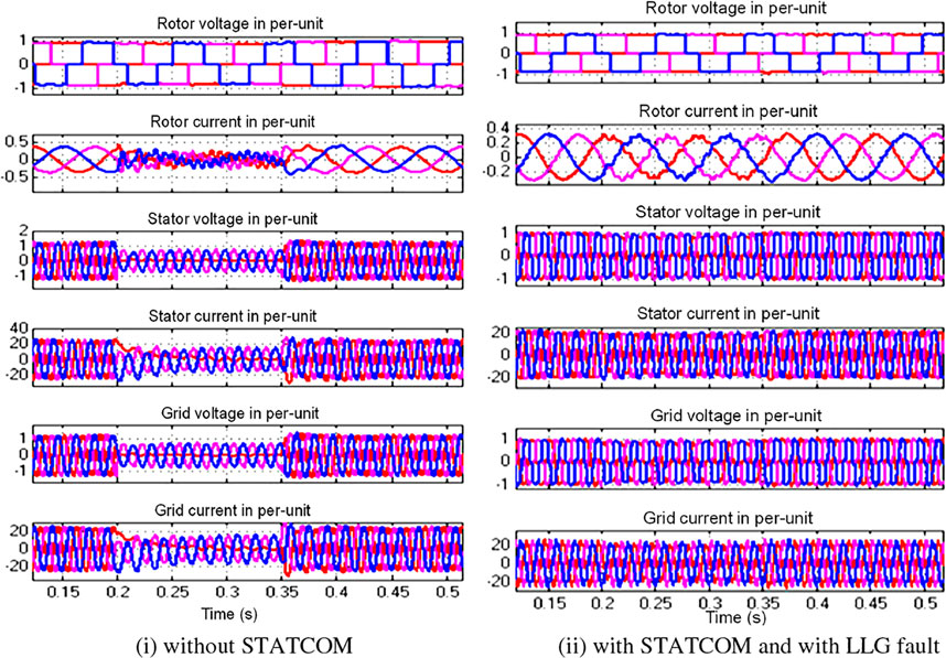
FIGURE 7. DFIG parameters computed in conventional and proposed cases. (i) Without STATCOM. (ii) With STATCOM and with LLG fault.
The stator and grid terminal current in faulty phases became zero slowly, and the current in the remaining two phases was reduced to half during the LLG fault when there is no STATCOM. However, with the STATCOM, there is a seamless operation without any transients observed in either rotor current or stator and grid side terminals.
The capacitor voltage, rotor speed, and the EMT waveforms without STATCOM for LLG fault are given in Figure 8i and with STATCOM in Figure 8ii per unit. It is observed that without STATCOM, there is a dip in dc-link voltage at the fault-happening instant, and it regained the normal value even when the fault is present. There is a small surge voltage from 1 pu to 1.23 pu that is observed at the instant when the fault is cleared. The rotor speed is almost constant but increased from 1.2 pu to 1.203 pu during the fault. The electromagnetic torque reached zero amplitude between a fault occurring and clearing instants. If a good controller-based STATCOM is used, there are not many changes in the system dynamics observed during severe faults as seen in Figure 8ii.
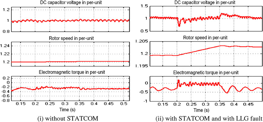
FIGURE 8. Back-to-back capacitor voltage, rotor speed, and electromagnetic torque of the DFIG. (i) Without STATCOM. (ii) With STATCOM and with LLG fault.
The dc-link voltage and rotor speed are almost constant during or after the fault compared to pre-fault. There is a small decrease in the electromagnetic torque that is observed because of a change in electro-mechanical power flow transfer during the fault. The bus 1 voltage without STATCOM during the fault decreased to almost zero and the current increased from 1 pu to 4 pu, while the bus 2 voltage at the receiving end is almost constant even with disturbance. The bus 2 current is almost constant but has small perturbations observed at fault-occurring and -clearing instants as shown in Figures 9i,ii. The bus 1 voltage is completely mitigated using the STATCOM device, and hence, the waveform shape is modified to a small extent during the fault from 0.2 to 0.35 s. The bus 1 current is reduced from 2 pu to 0.4 pu during the fault. This current is bypassed using the STATCOM voltage source converter to mitigate the bus voltages and to enhance the DFIG system performance during the transients. The bus 2 current has small disturbances with the STATCOM device during the fault and after the fault-clearing instants for some cycles.
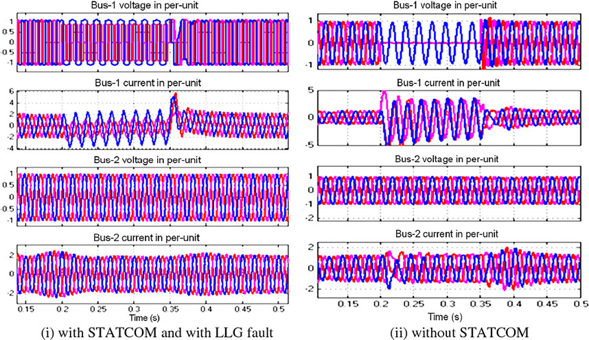
FIGURE 9. HVDC sending-end (bus 1) and receiving-end side (bus 2) AC voltage and current. (i) With STATCOM and with LLG fault. (ii) Without STATCOM.
The dc-link voltage at the HVDC terminal has small changes in the magnitude for LLG fault, and the performance is the exact opposite when the system is without and with STATCOM. There is a dip and surge in bus 1 voltage without STATCOM, while there is a surge and dip in bus 1 voltage with STATCOM due to the change in reactive power profiles and current flows in the bus terminals and in the STATCOM terminals as shown in Figures 10i,ii. Bus 1 sending-end voltage without STATCOM dipped to almost zero during the fault but regained its pre-fault value instantly without STATCOM. The d and q axis of sending-end current also increased to a large value during the fault without STATCOM. Once STATCOM is placed, the sending-end voltage dip is only from 1 pu to 0.8 pu and is well compensated.
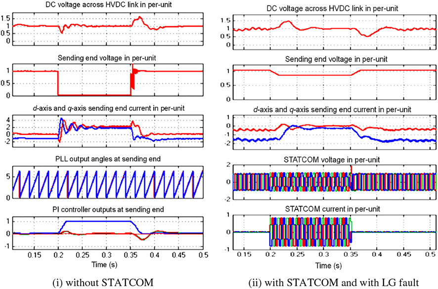
FIGURE 10. HVDC dc-link voltage, RMS value of SE side ac voltage, d and q axis currents at SE side, PLL angles, and PI controller outputs. (i) Without STATCOM. (ii) With STATCOM and with LG fault.
Similarly, the d-axis current changed to a small value while the q-axis current changed in magnitude from −1.8 pu to almost zero per unit during the fault and regained normally. The STATCOM-injected current during the fault is very quick and accurate and increased from nearly 0 pu to 0.9 pu within a short time interval.
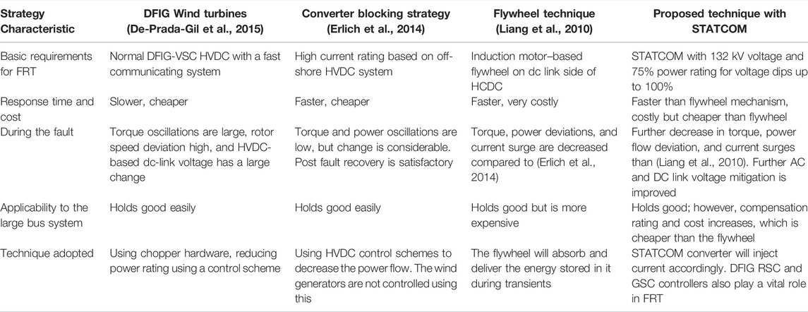
The results are better than the HVDC waveforms with the reference studies (Tang et al., 2016) and (Erlich et al., 2014) without STATCOM and with the proposed IFOC control scheme in terms of better current surge control and voltage mitigation during the faults. The comparison of the present work with earlier famous works is presented in the table for kind reference to show the effectiveness of the proposed work.
5.1 Comparison of the Proposed and Conventional Work
Figure 11i shows the DFIG rotor, stator, and grid voltage and current with the control scheme proposed in the study by (Moawwad et al., 2016). Figure 11ii shows the novel proposed method to compensate for the rotor voltage. With the approach employed in the study by (Moawwad et al., 2016), a 50% dip is observed in the rotor current and raised to 2 times the initial value after the fault is cleared. However, this rotor current is wholly compensated using our technique during the fault and has small ripples that can be neglected. Also, post-fault behavior is entirely satisfactory and settled to pre-fault value instantly. Because the stator is directly linked to the grid, stator and grid voltages are similar and the same are provided for comparison. The voltage and current dip considered is 50% of the normal value from 0.2 to 0.3 s. The post-fault current surge lasts for one cycle with the controller proposed in the study by (Moawwad et al., 2016). Nevertheless, there is a sufficient level of stability. With the proposed technique, the stator and grid voltage and current are compensated during the fault, and the post-fault behavior with the proposed control scheme is observed to be nearly identical to that in the pre-fault state.
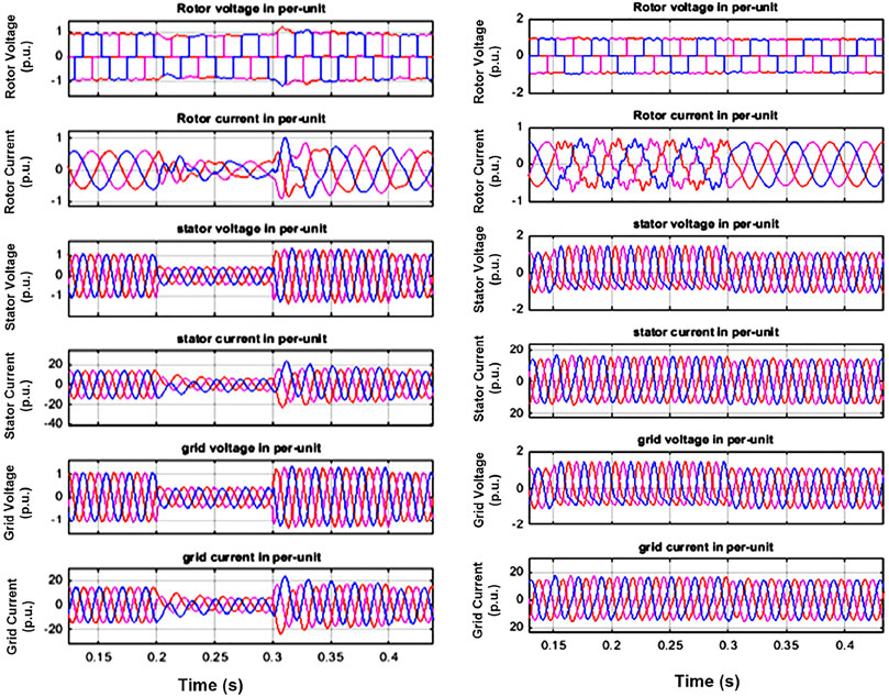
FIGURE 11. DFIG rotor, stator, and grid voltage and current with (i) control scheme (Moawwad et al., 2016) and (ii) proposed technique.
Under the fault period, a very slight increase in current(s) is to be observed, that is, from 1 to 1.25 p.u., and the post-fault state is identical to the pre-fault state. As a result, the IFOC-based RSC’s outer control loop method that is proposed in this work improves the overall performance of the DFIG parameters. Lookup table–based actual power and wind speed data are given in Table 3 (Justo et al., 2015).
The HVDC dc-link voltage, sending-end (SE) terminal voltage, direct (d) and quadrature (q) axis currents at the SE, PLL angles (radian units), PI controller error values for the HVDC converter three PI controllers’ values with the work in (Moawwad et al., 2016) is in Figure 12i and with our technique is in Figure 12ii. During the fault, the dc-link voltage is kept at one p.u., and the pre-fault value is also one p.u. Controlled oscillations, on the other hand, are detected during the post-fault, which are almost identical to those recorded during and after the fault using our suggested approach.
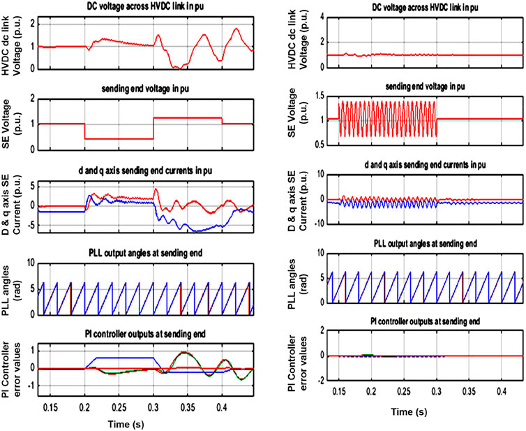
FIGURE 12. HVDC dc-link common voltage and SE voltage, d and q axis currents at SE, PLL angles at SE, and current PI controller error values with (i) control scheme (Moawwad et al., 2016) and (ii) proposed technique.
The sending-end (SE) voltage has a dip to 50% during the fault and a 1.25 times rise after the fault is observed for 1 s with our approach. During the fault, the voltage remains oscillating in the range of 1.25 to 0.75. The d axis current, which was 0 pu before the fault, climbed to 1 pu during the fault and oscillated in a regulated manner afterward. Before the incident, the q axis current was −1pu, but it changed to 0.5 pu during the failure. Its operation has been disrupted as a result of the post-fault behavior. The q-axis current changed to −5 pu for 1 s and slowly reached its pre-fault stage after 1 s of the fault clearing. The d-axis current is oscillatory with the 0.5-pu value with zero as the average value during the fault. The q-axis current is oscillatory from −0.75 to −1.5 pu with the reference value at −1pu using the proposed method. The post-fault is the same as the pre-fault operation.
The PLL behavior is the same in both ways. The PI controller’s error values with reference values have more deviation from its normal value during and after the fault and the PI controller error values at 0 pu during and after the fault like in post-fault.
The DFIG parameters for the work in Figure 13i and with our suggested approaches, such as back-to-back dc linkage capacitor voltage in volts, rotor speed, and electromagnetic torque (EMT) in pu, are presented in Figures 13i,ii. The capacitor voltage is practically the same as during-fault, while the post-fault voltage surged to 600 V immediately after the fault is cleared and reached 500 V, while this voltage is the same as pre-fault, during the fault, and post-fault with our proposed technique. The rotor speed is also the same without much deviation with both approaches. There is a slight deviation of −0.02 pu, which is negligible, and no variation is observed with our method. During the fault, the electro-magnetic torque (EMT) dropped from −0.45 pu to −0.05 pu. When the problem is cleared, the torque surges to −0.55 pu and then returns to its stable value after 1.5 s. With our technique, the EMT has maintained oscillations values ranging from 0.25 pu to 0.5 pu, never hitting 0 or a lower value, and achieving a stable value within 0.03 s after the fault is cleared. The overall behavior is more satisfied with our work than with the earlier work.
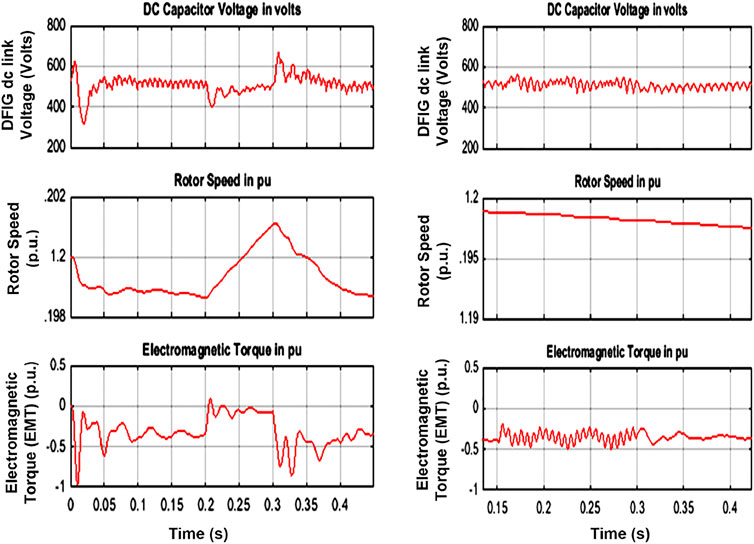
FIGURE 13. . DFIG back-to-back converter dc-link voltage, rotor speed, and EMT with (i) control scheme (Moawwad et al., 2016) and (ii) proposed technique.
The critical remarks observed from the results are as follows: the maintenance of DFIG converters’ capacitor dc-link voltage is crucial to sustaining efficiency under the grid faults. In addition, the GSC can offer reactive power, such as a shunt compensator, to achieve a better voltage profile once the problem is removed. As a result, an effective GSC control method is critical for FRT strategy. During a symmetrical fault, the suggested technique achieves a seamless switch in EMT. Because the dynamic stability of DFIG is improved, the suggested method’s correction of generator voltages and current is improved. Using the lookup table approach, the output DFIG power is efficiently damped, and the transient stator flux is minimized. Otherwise, over-current rotor winding degrades DFIG performance and reliability in the presence of these disturbances.
6 Conclusion
This study presents the IFOC method for the DFIG VSC–HVDC hybrid system to operate effectively for symmetrical as well as asymmetrical grid faults. The technique does not produce over-voltage or inrush surge currents in the DFIG winding or across the dc capacitor of the back-to-back converters under these disturbances. The torque oscillations are damped effectively and the rotor speed is within the safe limits during both types of faults. The HVDC sending-end terminal voltage dropped to a small value, and its current increased dangerously when the fault occurred near the sending-end side with the DFIG interconnection point. However, results are more promising with the proposed strategy than with the literature works. For further improvement of the system response during and after the fault, STATCOM with a new control is used and found to be very effective in improving the voltage profile and stability of the DFIG system connected to the HVDC transmission. The voltage and power profile of the DFIG system is improved considerably, and also, the HVDC sending-end terminal profile also improved drastically with our proposed method.
Data Availability Statement
The original contributions presented in the study are included in the article/supplementary material, further inquiries can be directed to the corresponding authors.
Author Contributions
All authors listed have made a substantial, direct, and intellectual contribution to the work and approved it for publication.
Conflict of Interest
The authors declare that the research was conducted in the absence of any commercial or financial relationships that could be construed as a potential conflict of interest.
The handling editor ZA declared a past co-authorship with the author FA.
Publisher’s Note
All claims expressed in this article are solely those of the authors and do not necessarily represent those of their affiliated organizations, or those of the publisher, the editors, and the reviewers. Any product that may be evaluated in this article, or claim that may be made by its manufacturer, is not guaranteed or endorsed by the publisher.
Acknowledgments
The authors extend their appreciation to the Deputyship for Research & Innovation, Ministry of Education, in Saudi Arabia, for funding this research work through the project number IF_2020_NBU_433. The authors gratefully thank the Prince Faisal bin Khalid bin Sultan Research Chair in Renewable Energy Studies and Applications (PFCRE) at Northern Border University for their support and assistance. The authors also thank the Start-up Research Grant (SRG) scheme of the Science and Engineering Research Board (SERB), a statutory body under the Department of Science and Technology (DST), Government of India, for supporting this work under project number SRG/2019/000648.
References
Abdelrahem, M., and Kennel, R. (2017). “Direct-model Predictive Control for Fault Ride-Through Capability Enhancement of DFIG,” in PCIM Europe 2017; International Exhibition and Conference for Power Electronics, Intelligent Motion, Renewable Energy and Energy Management (Nuremberg, Germany: VDE), 1–8.
Abdou, A. F., Abu-Siada, A., and Pota, H. R. (2015). Impact of VSC Faults on Dynamic Performance and Low Voltage Ride through of DFIG. Int. J. Electr. Power & Energy Syst. 65, 334–347. doi:10.1016/j.ijepes.2014.10.014
Ahmed, M., El-Shimy, M., and Badr, M. A. (2014). Advanced Modeling and Analysis of the Loading Capability Limits of Doubly-Fed Induction Generators. Sustain. Energy Technol. Assessments 7, 79–90. doi:10.1016/j.seta.2014.03.002
Ali, M. M., Youssef, A. R., Ali, A. S., and Abdel-Jaber, G. T. (2019). Comparative Study of Different Pitch Angle Control Strategies for DFIG Based on Wind Energy Conversion System. Int. J. Renew. Energy Res. 9 (1), 157–163. doi:10.20508/ijrer.v9i1.8721.g7573
Amin, M., Molinas, M., Lyu, J., and Cai, X. (2017). Impact of Power Flow Direction on the Stability of VSC-HVDC Seen from the Impedance Nyquist Plot. IEEE Trans. Power Electron. 32 (10), 8204–8217. doi:10.1109/tpel.2016.2608278
Ananth, D. V. N., and Nagesh Kumar, G. V. (2016). Fault Ride-Through Enhancement Using an Enhanced Field Oriented Control Technique for Converters of Grid Connected DFIG and STATCOM for Different Types of Faults. ISA Trans. 62, 2–18. doi:10.1016/j.isatra.2015.02.014
Ananth, D. V. N. (2018). Performance Enhancement of Grid Connected Doubly Fed Induction Generator under Source and Grid Side Issues. Ph.D. thesis (Shodganga: GITAM University).
Arman, S., Hosseinian, S. H., and Abyaneh, H. A. (2017). Enhancing the HVRT and LVRT Capabilities of DFIG-Based Wind Turbine in an Islanded Microgrid. Eng. Technol. Appl. Sci. Res. 7 (6), 2118–2123.
Ashrafi Niaki, S. H., Kazemi Karegar, H., and Ghalei Monfared, M. (2015). A Novel Fault Detection Method for VSC-HVDC Transmission System of Offshore Wind Farm. Int. J. Electr. Power & Energy Syst. 73, 475–483. doi:10.1016/j.ijepes.2015.04.014
Baimel, D., Chowdhury, N., Belikov, J., and Levron, Y. (2021). New Type of Bridge Fault Current Limiter with Reduced Power Losses for Transient Stability Improvement of DFIG Wind Farm. Electr. Power Syst. Res. 197, 107293. doi:10.1016/j.epsr.2021.107293
Benbouhenni, H., and Bizon, N. (2021). Advanced Direct Vector Control Method for Optimizing the Operation of a Double-Powered Induction Generator-Based Dual-Rotor Wind Turbine System. Mathematics 9 (19), 2403. doi:10.3390/math9192403
Bhattacharyya, S., and Singh, B. (2022). Wind-Driven DFIG-Battery-PV Based System with Advance DSOSF-FLL Control. IEEE Trans. Industry Appl. doi:10.1109/tia.2022.3171750
Boubzizi, S., Abid, H., El hajjaji, A., and Chaabane, M. (2018). Comparative Study of Three Types of Controllers for DFIG in Wind Energy Conversion System. Prot. Control Mod. Power Syst. 3 (1), 1–12. doi:10.1186/s41601-018-0096-y
Bounadja, E., Djahbar, A., and Boudjema, Z. (2014). Variable Structure Control of a Doubly Fed Induction Generator for Wind Energy Conversion Systems. Energy Procedia 50, 999–1007. doi:10.1016/j.egypro.2014.06.119
Bozhko, S., Asher, G., Li, R., Clare, J., and Yao, L. (2008). Large Offshore DFIG-Based Wind Farm with Line-Commutated HVDC Connection to the Main Grid: Engineering Studies. IEEE Trans. Energy Convers. 23 (1), 119–127. doi:10.1109/tec.2007.914155
Castro, L. M., and Acha., E. (2018). A New Method to Assess the Contribution of VSC-HVDC Connected Wind Farms to the Primary Frequency Control of Power Networks. Electr. Power Syst. Res. 154, 48–58. doi:10.1016/j.epsr.2017.08.011
Chandravanshi, S., and Gupta, S. (2021). “DFIG-based Wind Turbine Using DVR with Neural Network Control for Augmentation of Fault Ride through,” in 2021 4th International Conference on Recent Developments in Control, Automation & Power Engineering (RDCAPE) (Noida, India: IEEE), 95–100. doi:10.1109/rdcape52977.2021.9633350
Conde D, E. R., Lunardi, A., Normandia Lourenço, L. F., and Sguarezi Filho, A. J. (2022). A Predictive Repetitive Current Control in Stationary Reference Frame for DFIG Systems under Distorted Voltage Operation. IEEE J. Emerg. Sel. Top. Power Electron. doi:10.1109/JESTPE.2022.3173973
Daoud, M. I., Massoud, A. M., Abdel-Khalik, A. S., Elserougi, A., and Ahmed, S. (2016). A Flywheel Energy Storage System for Fault Ride through Support of Grid-Connected VSC HVDC-Based Offshore Wind Farms. IEEE Trans. Power Syst. 31 (3), 1671–1680. doi:10.1109/tpwrs.2015.2465163
De-Prada-Gil, M., Díaz-González, F., Gomis-Bellmunt, O., and Sumper, A. (2015). DFIG-based Offshore Wind Power Plant Connected to a Single VSC-HVDC Operated at Variable Frequency: Energy Yield Assessment. Energy 86, 311–322. doi:10.1016/j.energy.2015.04.038
Debouza, M., Al-Durra, A., Errouissi, R., and Muyeen, S. M. (2018). Direct Power Control for Grid-Connected Doubly Fed Induction Generator Using Disturbance Observer Based Control. Renew. Energy 125, 365–372. doi:10.1016/j.renene.2018.02.121
Debouza, M., Errouissi, R., Al-Durra, A., and Muyeen, S. M. (2016). “Design and Implementation of a Robust State-Feedback Control Law for a Grid-Connected Doubly Fed Induction Generator Wind Turbine,” in 5th IET International Conference on Renewable Power Generation (RPG), 30 January 2017. doi:10.1049/cp.2016.0568
Din, Z., Zhang, J., Xu, Z., Zhang, Y., Ahmad, H., Milyani, K. M. C., et al. (2022). Recent Development and Future Trends of Resonance in Doubly Fed Induction Generator System under Weak Grid. IET Renew. Power Gener. 16, 807. doi:10.1049/rpg2.12378
Döşoğlu, M. K., Güvenç, U., Sönmez, Y., and Yılmaz, C. (2018). Enhancement of Demagnetization Control for Low-Voltage Ride-Through Capability in DFIG-Based Wind Farm. Electr. Eng. 100 (2), 491–498. doi:10.1007/s00202-017-0522-6
Ebner, G., Doring, D., Schettler, F., Wurflinger, K., and Zeller, M. (2018). Fault Handling at Hybrid High-Voltage AC/DC Transmission Lines with VSC Converters. IEEE Trans. Power Deliv. 33 (2), 901–908. doi:10.1109/tpwrd.2017.2748163
Erlich, I., Feltes, C., and Shewarega, F. (2014). Enhanced Voltage Drop Control by VSC-HVDC Systems for Improving Wind Farm Fault Ridethrough Capability. IEEE Trans. Power Deliv. 29 (1), 378–385. doi:10.1109/tpwrd.2013.2285236
Ganthia, B. P., Barik, S. K., and Nayak, B. (2022). Genetic Algorithm Optimized and Type-I Fuzzy Logic Controlled Power Smoothing of Mathematical Modeled Type-III DFIG Based Wind Turbine System. Mater. Today Proc. 56, 3355–3365. doi:10.1016/j.matpr.2021.10.193
Gasmi, H., Mendaci, S., Laifa, S., Kantas, W., and Benbouhenni, H. (2022). Fractional-order Proportional-Integral Super Twisting Sliding Mode Controller for Wind Energy Conversion System Equipped with Doubly Fed Induction Generator. J. Power Electron. 2022, 1–17. doi:10.1007/s43236-022-00430-0
Giddani, O. A., Adam, G. P., Anaya-Lara, O., Burt, G., and Lo, K. L. (2010). “Control Strategies of VSC-HVDC Transmission System for Wind Power Integration to Meet GB Grid Code Requirements,” in 2010 International Symposium on Power Electronics, Electrical Drives Automation and Motion (SPEEDAM) (Pisa, Italy: IEEE), 385–390. doi:10.1109/speedam.2010.5542237
Gorenstein Dedecca, J., Lumbreras, S., Ramos, A., Hakvoort, R. A., and Herder, P. M. (2018). Expansion Planning of the North Sea Offshore Grid: Simulation of Integrated Governance Constraints. Energy Econ. 72, 376–392. doi:10.1016/j.eneco.2018.04.037
Guo, C., Liu, W., Zhao, C., and Iravani, R. (2017). A Frequency-Based Synchronization Approach for the Vsc-Hvdc Station Connected to a Weak Ac Grid. IEEE Trans. Power Deliv. 32 (3), 1460–1470. doi:10.1109/tpwrd.2016.2606495
Haidar, A. M. A., Muttaqi, K. M., and Hagh, M. T. (2017). A Coordinated Control Approach for DC Link and Rotor Crowbars to Improve Fault Ride-Through of DFIG-Based Wind Turbine. IEEE Trans. Ind. Appl. 53 (4), 4073–4086. doi:10.1109/tia.2017.2686341
Hannoon, N. M. S., Ananth, D. V. N., Hidayat, M. N. B., Chowdary, P. S. R., Chakravarthy, V. V. S. S. S., Sivashankar, K., et al. (2021). A Common Capacitor Based Three Level STATCOM and Design of DFIG Converter for a Zero-Voltage Fault Ride-Through Capability. IEEE Access 9, 105153–105179. doi:10.1109/access.2021.3098187
Hiremath, R., and Moger, T. (2022). Modified Super Twisting Algorithm Based Sliding Mode Control for LVRT Enhancement of DFIG Driven Wind System. Energy Rep. 8, 3600–3613. doi:10.1016/j.egyr.2022.02.235
Hu, B., Nian, H., Meng, L., and Xu, Y. (2020). Impedance Characteristic Analysis and Reshaping Method of DFIG System Based on DPC without PLL. IEEE Trans. Industrial Electron. 68 (10), 9767–9777. doi:10.1109/TIE.2020.3028826
Huang, J., and Li, S. (2020). Asymmetrical LVRT of DFIG Incorporating Feed‐forward Transient Current Control and Controllable Resistive‐type Fault Current Limiter. IEEJ Trans. Elec Electron Eng. 15 (7), 1100–1108. doi:10.1002/tee.23155
Huang, Q., Zou, X., Zhu, D., and Kang, Y. (2015). Scaled Current Tracking Control for Doubly Fed Induction Generator to Ride-Through Serious Grid Faults. IEEE Trans. Power Electron. 31 (3), 2150–2165. doi:10.1109/TPEL.2015.2429153
Huo, Z., and Xu, C. (2022). Distributed Cooperative Automatic Generation Control and Multi-Event Triggered Mechanisms Co-design for Networked Wind-Integrated Power Systems. Renew. Energy 193, 41. doi:10.1016/j.renene.2022.05.011
Ismail, M. M., and Bendary, A. F. (2016). Protection of DFIG Wind Turbine Using Fuzzy Logic Control. Alexandria Eng. J. 55 (2), 941–949. doi:10.1016/j.aej.2016.02.022
Justo, J. J., and Bansal, R. C. (2018). Parallel R-L Configuration Crowbar with Series R-L Circuit Protection for LVRT Strategy of DFIG under Transient-State. Electr. Power Syst. Res. 154, 299–310. doi:10.1016/j.epsr.2017.09.002
Justo, J. J., Mwasilu, F., and Jung, J. W. (2014). Doubly Fed Induction Generator Wind Turbines: A Novel Integrated Protection Circuit for Low-Voltage Ride-Through Strategy. J. Renew. Sustain. Energy 6 (5), 053129. doi:10.1063/1.4899076
Justo, J. J., Mwasilu, F., and Jung, J. W. (2015). Doubly-fed Induction Generator Based Wind Turbines: A Comprehensive Review of Fault Ride-Through Strategies. Renew. Sustain. energy Rev. 45, 447–467. doi:10.1016/j.rser.2015.01.064
Justo, J. J., Mwasilu, F., and Jung, J. W. (2017). Enhanced Crowbarless FRT Strategy for DFIG Based Wind Turbines under Three-phase Voltage Dip. Electr. Power Syst. Res. 142, 215–226. doi:10.1016/j.epsr.2016.09.029
Kadri, A., Marzougui, H., Aouiti, A., and Bacha, F. (2020). Energy Management and Control Strategy for a DFIG Wind Turbine/fuel Cell Hybrid System with Super Capacitor Storage System. Energy 192, 116518. doi:10.1016/j.energy.2019.116518
Kelkoul, B., and Boumediene, A. (2021). Stability Analysis and Study between Classical Sliding Mode Control (SMC) and Super Twisting Algorithm (STA) for Doubly Fed Induction Generator (DFIG) under Wind Turbine. Energy 214, 118871. doi:10.1016/j.energy.2020.118871
Khan, M. S. H., and Mallik, S. K. (2022). Mechanical Sensorless Control of a Rotor-Tied DFIG Wind Energy Conversion System Using a High Gain Observer. J. King Saud University-Engineering Sci. doi:10.1016/j.jksues.2022.05.005
Khazaei, J., Idowu, P., Asrari, A., Shafaye, A., and Piyasinghe, L. (2018). Review of HVDC Control in Weak AC Grids. Electr. Power Syst. Res. 162, 194–206. doi:10.1016/j.epsr.2018.05.022
Korompili, A., Wu, Q., and Zhao, H. (2016). Review of VSC HVDC Connection for Offshore Wind Power Integration. Renew. Sustain. Energy Rev. 59, 1405–1414. doi:10.1016/j.rser.2016.01.064
Kucukaydin, B., and Arikan, O. (2022). A Comparative Study on Applicability of Parallel Resonance Type Fault Current Limiters in Power Systems. Teh. Vjesn. 29 (3), 993–1001.
Kumar, Y. V. P., and Ravikumar, B. (2017). “Fuzzy Logic Based Adaptive Virtual Inertia in Droop Control Operation of the Microgrid for Improved Transient Response,” in 2017 IEEE PES Asia-Pacific Power and Energy Engineering Conference (APPEEC), Bangalore, India, 1–6. doi:10.1109/appeec.2017.8309006
Kumar, Y. V. P., and Ravikumar, B. (2016). “Improving Power Quality in Microgrids Using Virtual Motor-Generator Set Based Control Scheme,” in IECON 2016 - 42nd Annual Conference of the IEEE Industrial Electronics Society, Florence, Italy, 7173–7178. doi:10.1109/iecon.2016.7793624
Leyla, A., and Marinescu, B. (2015). Multivariable Control with Grid Objectives of an HVDC Link Embedded in a Large-Scale AC Grid. Int. J. Electr. Power & Energy Syst. 72, 99–108.
Liang, J., Qiao, W., and Harley, R. G. (2010). Feed-Forward Transient Current Control for Low-Voltage Ride-Through Enhancement of DFIG Wind Turbines. IEEE Trans. Energy Convers. 25 (3), 836–843. doi:10.1109/tec.2010.2048033
Madariaga, A., Martín, J. L., Zamora, I., Martínez de Alegría, I., and Ceballos, S. (2013). Technological Trends in Electric Topologies for Offshore Wind Power Plants. Renew. Sustain. Energy Rev. 24, 32–44. doi:10.1016/j.rser.2013.03.039
Mahish, P., and Mishra, S. (2022). Synchrophasor Data Based QV Droop Control of Wind Farm Integrated Power Systems. IEEE Trans. Power Syst. doi:10.1109/tpwrs.2022.3163337
Moawwad, A., El Moursi, M. S., and Xiao, W. (2016). Advanced Fault Ride-Through Management Scheme for VSC-HVDC Connecting Offshore Wind Farms. IEEE Trans. Power Syst. 31 (6), 4923–4934. doi:10.1109/tpwrs.2016.2535389
Mohamed, M. A., Diab, A. A. Z., Rezk, H., and Jin, T. (2020). A Novel Adaptive Model Predictive Controller for Load Frequency Control of Power Systems Integrated with DFIG Wind Turbines. Neural Comput. Applic 32 (11), 7171–7181. doi:10.1007/s00521-019-04205-w
Mohseni, M., Masoum, M. A. S., and Islam, S. M. (2011). Low and High Voltage Ride-Through of DFIG Wind Turbines Using Hybrid Current Controlled Converters. Electr. Power Syst. Res. 81 (7), 1456–1465. doi:10.1016/j.epsr.2011.02.010
Nair, R., and Narayanan, G. (2020). Stator Flux Based Model Reference Adaptive Observers for Sensorless Vector Control and Direct Voltage Control of Doubly-Fed Induction Generator. IEEE Trans. Industry Appl. 56 (4), 3776–3789. doi:10.1109/tia.2020.2988426
Nanou, S. I., and Papathanassiou, S. A. (2016). Grid Code Compatibility of VSC-HVDC Connected Offshore Wind Turbines Employing Power Synchronization Control. IEEE Trans. Power Syst. 31 (6), 5042–5050. doi:10.1109/tpwrs.2016.2515504
Nanou, S. I., Patsakis, G. N., and Papathanassiou, S. A. (2015). Assessment of Communication-independent Grid Code Compatibility Solutions for VSC-HVDC Connected Offshore Wind Farms. Electr. Power Syst. Res. 121, 38–51. doi:10.1016/j.epsr.2014.12.002
Noureldeen, O. (2012). Behavior of DFIG Wind Turbines with Crowbar Protection under Short Circuit. Int. J. Electr. Comput. Sci. IJECS-IJENS 12 (3), 32–37.
Paliwal, P. (2022). A State-Of-The-Art Review on LVRT Enhancement Techniques for DFIG-Based Wind Turbines. Adv. Energy Technol. 766, 131–141. doi:10.1007/978-981-16-1476-7_13
Prasad, R., and Padhy, N. P. (2020). Synergistic Frequency Regulation Control Mechanism for DFIG Wind Turbines with Optimal Pitch Dynamics. IEEE Trans. Power Syst. 35 (4), 3181–3191. doi:10.1109/tpwrs.2020.2967468
Priti, S., and Kumar, A. (2016). Thevenin’s Equivalent Based P–Q–V Voltage Stability Region Visualization and Enhancement with FACTS and HVDC. Int. J. Electr. Power & Energy Syst. 80, 119–127.
Rini Ann Jerin, A., Kaliannan, P., Subramaniam, U., and Shawky El Moursi, M. (2018). Review on FRT Solutions for Improving Transient Stability in DFIG‐WTs. IET Renew. Power Gener. 12 (15), 1786–1799. doi:10.1049/iet-rpg.2018.5249
Shabbir, M. N. S. K., Liang, X., and Chakrabarti, S. (2022). A Hierarchical Voltage Control Scheme for Wind Power Plants through Enhanced Reactive Power Support. IEEE Trans. Ind. Appl. 2022, 1. doi:10.1109/tia.2022.3179972
Surinkaew, T., and Ngamroo, I. (2016). Hierarchical Co-ordinated Wide Area and Local Controls of DFIG Wind Turbine and PSS for Robust Power Oscillation Damping. IEEE Trans. Sustain. Energy 7 (3), 943–955. doi:10.1109/tste.2015.2508558
Tang, Y., He, H., Ni, Z., Wen, J., and Huang, T. (2016). Adaptive Modulation for DFIG and STATCOM with High-Voltage Direct Current Transmission. IEEE Trans. Neural Netw. Learn. Syst. 27 (8), 1762–1772. doi:10.1109/tnnls.2015.2504035
Varma, D. K., Obulesh, Y. P., and Babu, C. S. (2015). Decoupled Feed Forward Voltage Oriented Controller for DFIG under Balanced and Unbalanced Fault Conditions. Tijee 15 (2), 209–216. doi:10.11591/tijee.v15i2.1533
V. Pavan Kumar, Y., and Bhimasingu, R. (2017). Electrical Machines Based DC/AC Energy Conversion Schemes for the Improvement of Power Quality and Resiliency in Renewable Energy Microgrids. Int. J. Electr. Power & Energy Syst. 90, 10–26. doi:10.1016/j.ijepes.2017.01.015
Wadawa, B., Errami, Y., Obbadi, A., Sahnoun, S., Chetouani, E., and Aoutoul, M. (2022). Comparative Application of the Self-Adaptive Fuzzy-PI Controller for a Wind Energy Conversion System Connected to the Power Grid and Based on DFIG. Int. J. Dyn. Control 2022, 1–23. doi:10.1007/s40435-022-00952-2
Wu, J., Wang, Z.-X., Xu, L., and Wang, G.-Q. (2014). Key Technologies of VSC-HVDC and its Application on Offshore Wind Farm in China. Renew. Sustain. Energy Rev. 36, 247–255. doi:10.1016/j.rser.2014.04.061
Xiao, S., Geng, Y., Zhou, H., and Geng, H. (2012). An LVRT Control Strategy Based on Flux Linkage Tracking for DFIG-Based WECS. IEEE Trans. Industrial Electron. 60 (7), 2820–2832. doi:10.1109/TIE.2012.2205354
Yang, J., Fletcher, J. E., and O'Reilly, J. (2010). A Series-Dynamic-Resistor-Based Converter Protection Scheme for Doubly-Fed Induction Generator during Various Fault Conditions. IEEE Trans. Energy Convers. 25 (2), 422–432. doi:10.1109/tec.2009.2037970
Yang, R. H., and Jin, J. X. (2020). Unified Power Quality Conditioner with Advanced Dual Control for Performance Improvement of DFIG-Based Wind Farm. IEEE Trans. Sustain. Energy 12 (1), 116–126. doi:10.1109/TSTE.2020.2985161
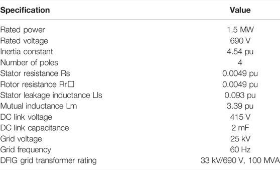
Appendix A: Simulation parameters of DFIG
Keywords: doubly fed induction generator (DFIG), field-oriented control, high-voltage dc transmission (HVDC), static synchronous compensator (STATCOM), symmetrical fault, wind farms, renewable energy, performance enhancement of DFIG based wind farms
Citation: Pavan Kumar YV, Kumar LVS, Ananth DVN, Reddy CP, Flah A, Kraiem H, Al-Asad JF, Kotb H and Aboras KM (2022) Performance Enhancement of Doubly Fed Induction Generator–Based Wind Farms With STATCOM in Faulty HVDC Grids. Front. Energy Res. 10:930268. doi: 10.3389/fenrg.2022.930268
Received: 27 April 2022; Accepted: 03 June 2022;
Published: 13 July 2022.
Edited by:
Ziad M. Ali, Aswan University, EgyptCopyright © 2022 Pavan Kumar, Kumar, Ananth, Reddy, Flah, Kraiem, Al-Asad, Kotb and Aboras. This is an open-access article distributed under the terms of the Creative Commons Attribution License (CC BY). The use, distribution or reproduction in other forums is permitted, provided the original author(s) and the copyright owner(s) are credited and that the original publication in this journal is cited, in accordance with accepted academic practice. No use, distribution or reproduction is permitted which does not comply with these terms.
*Correspondence: Yellapragada Venkata Pavan Kumar, cGF2YW5rdW1hci55dkB2aXRhcC5hYy5pbg==; Habib Kraiem, aGFiaWIua3JhaWVtQHlhaG9vLmZy
 Yellapragada Venkata Pavan Kumar
 Lagudu Venkata Suresh Kumar2
 Aymen Flah
 Habib Kraiem
 Hossam Kotb
 Kareem M. Aboras