 Haiqi Qin
 Xiaowei Luo
 Xiaowei Li
94% of researchers rate our articles as excellent or good
Learn more about the work of our research integrity team to safeguard the quality of each article we publish.
Find out more
ORIGINAL RESEARCH article
Front. Energy Res., 07 July 2022
Sec. Nuclear Energy
Volume 10 - 2022 | https://doi.org/10.3389/fenrg.2022.925380
This article is part of the Research TopicExperimental and Simulation Research on Nuclear Reactor Thermal-HydraulicsView all 15 articles
High working temperature is a major feature of the high temperature gas-cooled reactor (HTGR). The helical tube once through steam generator (OTSG) should maintain appropriate temperature uniformity. The temperature non-uniformity of the HTGR OTSG includes the in-unit and inter-unit temperature non-uniformity, while the latter is mainly induced by the inter-unit flow rate non-uniformity of primary-side hot helium, which is significantly affected by the inlet structure. In this work, a new inlet structure with a hot helium flow homogenizer is designed, and its flow distribution characteristics are numerically investigated. Accordingly, the optimal geometrical parameters are determined, such as the circular hole diameter on the end wall, the square hole size, and arrangement on the cylinder wall. Increasing the resistance of the flow homogenizer with non-uniformly arranged square holes (NUASHs) can improve inter-unit flow rate uniformity because it decreases the effect of static pressure difference caused by dynamic pressure. Two design parameters (resistance coefficient and flow area ratio of the square hole on both sides) are introduced to evaluate the structure effect of the hot helium flow homogenizer on inter-unit flow rate distribution. They are recommended within the ranges of (7.81–22.42) and (0.53–1.64), respectively. In these recommended ranges, the suction phenomenon near the hot helium inlet can be effectively suppressed, with the critical resistance coefficient of 7.63. By coupling with 19 heat exchange units, the overall performance of the hot helium flow homogenizer is better than that of the current inlet structure with a baffle, with the maximum inter-unit flow rate deviation decreased from 2.97% to 0.30%. This one-magnitude enhancement indicates that the hot helium flow homogenizer with NUASHs is a promising solution to improve inter-unit flow rate uniformity of the HTGR OTSG.
The high temperature gas-cooled reactor (HTGR) has the characteristics of the fourth-generation advanced nuclear power system. It has the outstanding advantages of excellent inherent safety, continuous fuel loading and discharging, high temperature and high power generation efficiency, etc. (Wu and Zhang, 2000; Wu et al., 2002; Generation-Ⅳ International Forum, 2002). HTGR can extend the nuclear energy application to high-temperature heat utilization and hydrogen production (Zhang and Sun, 2007; Zhang et al., 2009). At the Shidao Bay site in China, the world’s first high-temperature gas-cooled reactor pebble-bed module (HTR-PM) demonstration power plant of 200MWe achieved criticality for the first time in September 2021, and was connected to the grid on December 20, 2021 (Zhang et al., 2016). On the basis of HTR-PM, a 600-MWe nuclear power plant has been proposed, as the next step of HTGR application in China.
The helical tube once through steam generator (OTSG) is an important equipment of the HTGR, which is characterized by its compact structure, high working temperature, and once through flow pattern. It is not only the pressure boundary of HTGR coolant but also the key heat exchanger between the primary and secondary loops. The primary-side helium absorbs fission heat from the reactor core and then heats the secondary-side water to superheated steam through the helical heat transfer tube bundles in the OTSG (Li et al., 2019a). Compared with the traditional U-tube natural circulation steam generator of the pressurized water reactor (PWR), the thermal hydraulic characteristics of the HTGR OTSG are quite different. Due to the high working temperature of 750°C, the design temperature of the helical heat transfer tube almost reaches the upper limit of the high-temperature material (Incoloy 800H) used in the HTGR OTSG. According to reference (ASME, 2015), the allowable stress of Incoloy 800H at 750°C will decrease to only one-tenth of that at normal temperature. The non-uniform temperature distribution may lead to the working temperature of certain helical heat transfer tubes above its design temperature. This will aggravate the material creep or even rupture the helical tubes. The representative examples were Heysham #1 and #2 advanced gas-cooled reactors (AGRs) built in the early 1980s in the UK. There was a large non-uniform temperature distribution among the helical heat transfer tubes of the OTSG during the commissioning. In order to ensure the maximum working temperature of the helical tube below the design temperature, the reactor operation power had to be reduced to 68% of the design value (Mathews, 1987). Therefore, the temperature non-uniformity can seriously affect the reliability and in-service lifecycle of the HTGR OTSG, which needs further detailed analysis.
The HTGR OTSG is generally composed of inlet structure and heat exchange units. The inlet structure consists of the primary-side hot helium inlet, upper chamber, main steam header, and support plate, as shown in Figure 1A. Moreover, there are 19 separate heat exchange units (19 helical heat transfer tube bundles) with identical geometrical parameters. Their arrangement is presented in Figure 1B.
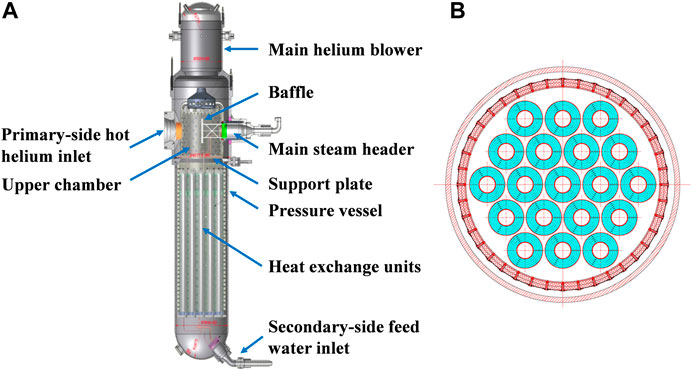
FIGURE 1. Schematic of the HTGR OTSG Zhang et al., 2009. (A) Geometrical model. (B) Cross section.
Primary-side hot helium enters the upper chamber from the inlet and then flows over the helical heat transfer tube bundles from the top to the bottom. The secondary-side cold water flows into the helical heat transfer tubes from the bottom to the top. This counterflow realizes the heat exchange between the primary and secondary loops.
The temperature non-uniformity of the HTGR OTSG can be divided into two types, that is, in-unit and inter-unit non-uniformity. This temperature non-uniformity classification has been analyzed in detail in the literatures (Li, 2012; Li et al., 2016; Gao, 2020). Works have been conducted to investigate the in-unit temperature non-uniformity (among the helical heat transfer tubes). It has been reported that the wall effect, helical effect, temperature mixing effect, reverse winding of adjacent helical tube layers in the tube bundle, and geometrical parameter variations induced by the fabrication tolerance are the main reasons for in-unit temperature non-uniformity (Li and Wu, 2013; Olson et al., 2014; Li et al., 2014; Iacovides et al., 2014; Li et al., 2019b; da Silva et al., 2019; Gao et al., 2020). Furthermore, the above-mentioned in-unit temperature non-uniformity has also been experimentally verified in the 10-MW engineering test facility-steam generator (ETF-SG) for the HTR-PM (Zhang et al., 2016). The inter-unit temperature non-uniformity is mainly influenced by the inlet structure and hot helium temperature uniformity at the OTSG inlet. Previous investigations have documented that the hot helium mixing structure installed at the reactor core outlet of the HTR-PM can realize the thermal mixing efficiency above 98% (Zhou et al., 2011; Zhou et al., 2016). Therefore, this study will focus on the effect of the HTGR OTSG inlet structure on inter-unit temperature non-uniformity.
In fact, the non-uniform flow rate distribution among the heat exchange units can result in significant inter-unit temperature non-uniformity. Existing research has proposed the structure with a baffle to improve inter-unit flow rate uniformity (Zhang et al., 2011). This is also the current inlet structure adopted by the HTR-PM. As a promising structure optimization, a new inlet structure (i.e., hot helium flow homogenizer) is designed in the present work. Its flow distribution characteristics are numerically investigated using the computational fluid dynamics (CFD) method. Then, the effects of different geometrical parameters on inter-unit flow rate uniformity are discussed. The optimal geometrical parameters of this newly designed hot helium flow homogenizer are proposed. Eventually, the overall flow rate distribution is simulated by coupling the inlet structure and 19 heat exchange units, to further verify the optimal geometrical parameters.
Figure 2 illustrates the geometrical model of the hot helium flow homogenizer.
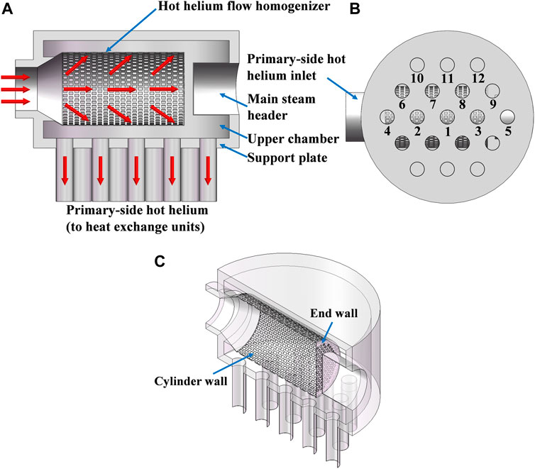
FIGURE 2. Schematic of the hot helium flow homogenizer. (A) Main view. (B) Bottom view. (C) Perspective view.
In Figure 2C, the hot helium flow homogenizer has a cylindrical structure, where the side and bottom are defined as the cylinder wall and end wall. For the cylinder wall, there are some rectangular holes (referred to as the square holes) distributed in a certain arrangement, while some circular holes are uniformly hollowed out on the end wall. The main steam header occupies a certain space of the upper chamber and shields several heat exchange units. It causes the asymmetrical structure of the hot helium flow homogenizer, which will affect inter-unit flow rate uniformity. The main geometrical parameters of the hot helium flow homogenizer are shown in Table 1.
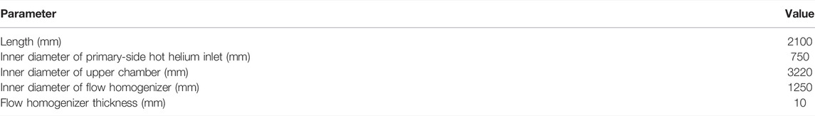
TABLE 1. Geometrical parameters of the hot helium flow homogenizer.
The numerical simulation is performed in two steps. First, the three-dimensional (3D) full-scale modeling is carried out for the inlet structure with the hot helium flow homogenizer. Using the commercial CFD code CFX, the inter-unit flow rate distribution is numerically simulated by solving the Reynolds Averaged Navier Stokes (RANS) governing equations together with the turbulence model (ANSYS, 2019). The superiority of the hot helium flow homogenizer, the necessity of further structure optimization, and the effects of geometrical parameter on flow rate distribution are evaluated. Second, the overall flow rate uniformity of the HTGR OTSG is further verified, considering the coupling of the inlet structure and 19 heat exchange units. As the basis, the first step is beneficial for understanding the flow distribution mechanism and independent structure design of the hot helium flow homogenizer. The second step emphasizes the overall performance of inter-unit flow rate uniformity. Figure 3 shows the flow chart of the steps in this investigation.
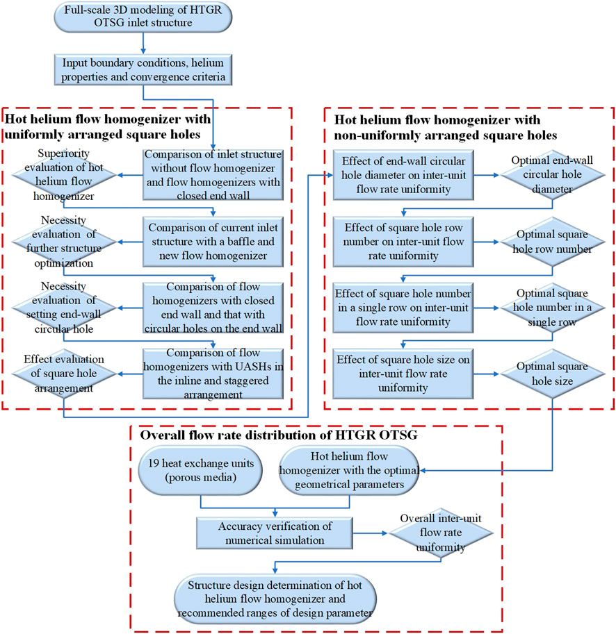
FIGURE 3. Flow chart of the investigation.
Neglecting some micro-structures such as the dead zone near the wall and grooves, the geometrical model of the inlet structure is reasonably simplified. In order to reduce the mesh element number, the porous media is used for the helical heat transfer tube bundles. Using hybrid grid technology, the computational domain is divided into two parts, including the fluid domain (the inlet structure with the hot helium flow homogenizer) and the porous media domains (19 heat exchange units). Among them, the tetrahedral unstructured mesh is automatically generated for the fluid domain and the hexahedral structured mesh is adopted for the porous media domains, respectively. These computational domains are connected by interfaces. The local mesh is refined near the square holes on the cylinder wall and circular holes on the end wall. Local mesh distribution is presented in Figure 4.

FIGURE 4. Local mesh distribution.
Due to the excellent thermal mixing at the reactor core outlet, the hot helium temperature is regarded as uniform at the inlet of the HTGR OTSG. Thus, all the cases in this work are 3D steady-state adiabatic simulations with helium as the working fluid. Additionally, the standard k-ε model and scalable wall treatment are selected for turbulence modeling. The reliability and stability of this turbulence model have been fully proved as a standard engineering model (Tao, 2017).
Mach number (Ma) reflects the influence of gas compressibility, which is used to classify whether the flow is compressible (Kong, 2014). The definition of Ma is given as Eq. 1.
where c is the local acoustic velocity.
When Ma is lower than 0.3, the gas compressibility has little effect on its flow characteristics, which can be considered as incompressible fluid. From Eq. 1, the corresponding Ma of primary-side hot helium is 0.039, so it can be treated as an incompressible viscous fluid with constant properties. Helium properties are calculated using the NIST real gas package which is a material database based on the Thermodynamic and Transport Properties of Refrigerants and Refrigerant Mixtures Database (REFPROP v9.1) provided by the National Institute of Standards and Technology (NIST) (Zhao et al., 2017; Gao et al., 2019). Table 2 lists the helium properties, where 5 significant digits are reserved.
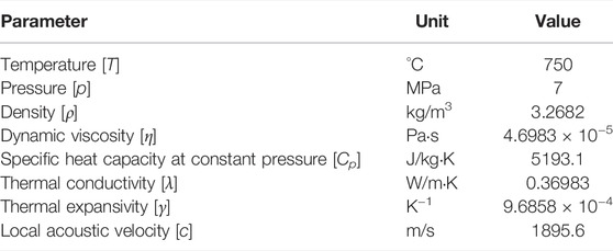
TABLE 2. Helium properties.
Taking into account the resistance equivalence, each heat exchange unit of 8 m height is simplified into a porous media domain of 1.2 m height, to simulate the hot helium cross flow over the helical heat transfer tube bundle. Volume porosity, permeability, and the resistance coefficient are important physical properties to represent the flow characteristics of porous media. Volume porosity is the ratio of the pore volume (fluid volume) to the total geometrical volume. For a single heat exchange unit, the volume of helical heat transfer tubes acts as the solid volume, while the difference between the total geometrical volume and this solid volume is defined as the fluid volume. Permeability (K) is an inherent property of porous media, which is determined by Darcy’s permeation law expressed in Eq. 2 (Satter and Iqbal, 2016; Hayat et al., 2021).
where Qv is the volume flow rate, L is the length, A is the flow area, and ∆p is the pressure drop.
For cross flow over the helical tube bundle, the resistance coefficient (ξ) is calculated using the empirical correlation proposed by Idelchik, as shown in Eq. 3 (Idelchik and Fried, 2016).
where S1 is the transverse tube pitch and S2 is the stream-wise tube pitch. In Eq. 3, Re and S1-d/S2-d are in the ranges of (3 × 10³–105) and (1.0–8.0), respectively.
Eq. 3 is converted into Eq. 4, which is substituted into the geometrical parameters of the helical tube bundle.
The characteristic velocity and hydraulic diameter of the Reynolds number (Re) are considered as the maximum average flow velocity at the minimum cross section in the helical tube bundle and the outer diameter of the helical tube, respectively.
Owing to the symmetrical structure and large size, symmetry boundary condition is assumed for the overall inlet structure of the HTGR OTSG. The inlet is specified with a constant mass flow rate of 48 kg/s and turbulence intensity of 5%. Static pressure in 0Pa is prescribed at the outlet. The smooth and non-slip wall boundary conditions are used for all the walls of the inlet structure, without considering the influence of wall roughness. The mesh connections are set as the conservative flux and general grid interface (GGI).
The convection term and turbulence equation are discretized using a high-resolution upwind scheme. Auto timescale and conservative length scale are adopted for the fluid timescale control. The convergence criteria are formulated as the root mean square residuals (RMSs) below 1 × 10⁻⁵.
The hot helium flow homogenizer with the optimal inter-unit flow rate uniformity is selected as an example to analyze the sensitivity of mesh element number. Six meshes are generated by adjusting the local mesh parameters. Their mesh qualities are all higher than 0.3, and the average y+ is below 70, meeting the calculation accuracy requirements and the application range of the standard k-ε turbulence model and wall function.
In the current investigation, the maximum deviation and standard deviation (σ) are taken as the uniformity evaluation standards of inter-unit flow rate distribution. If the inter-unit flow rate distribution is completely uniform, the corresponding mass flow rate of each heat exchange unit should be 5.053 kg/s. The maximum inter-unit flow rate deviation is defined as the relative difference between the maximum and minimum mass flow rates among 19 heat exchange units. The standard deviation characterizes the dispersion degree of inter-unit flow rate distribution. The larger value of these uniformity evaluation parameters means a large inter-unit flow rate difference. In addition, the mass flow rate within 14 rows of square holes reveals the flow distribution characteristics of the flow homogenizer. The variation of the above uniformity evaluation parameters is shown in Figure 5.
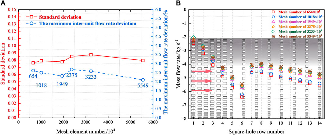
FIGURE 5. Sensitivity analysis. (A) Variation with mesh element number. (B) Flow distribution characteristics.
On the whole, the meshes have little effect on the numerical results. From Figure 5A, within the mesh element number of 6.54–55.49 million, the variation amplitude of the maximum inter-unit flow rate deviation is below 0.5%. In Figure 5B, there are almost similar flow distribution characteristics in different meshes. Especially when the mesh element number is more than 20 million, the mass flow rate within each row of square holes tends to be consistent, with the relative error being less than 1%. Further mesh refinement has no obvious improvement on numerical results. Considering the calculation accuracy and convergence speed, the working mesh is determined as 23.75 million.
This group of numerical simulations is used to qualitatively evaluate the effect of the hot helium flow homogenizer on inter-unit flow rate distribution. Nevertheless, the specific structure design and geometrical parameters still need to be further explored. The inlet structure numbered 1 is not equipped with the hot helium flow homogenizer, while the previously designed inlet structure with a baffle is numbered 2. Other inlet structures numbered 3–10 are equipped with hot helium flow homogenizers, in which square holes are uniformly arranged on the cylinder wall. As for the hot helium flow homogenizer with uniformly arranged square holes (UASHs), the characteristic geometrical parameters are listed in Table 3.
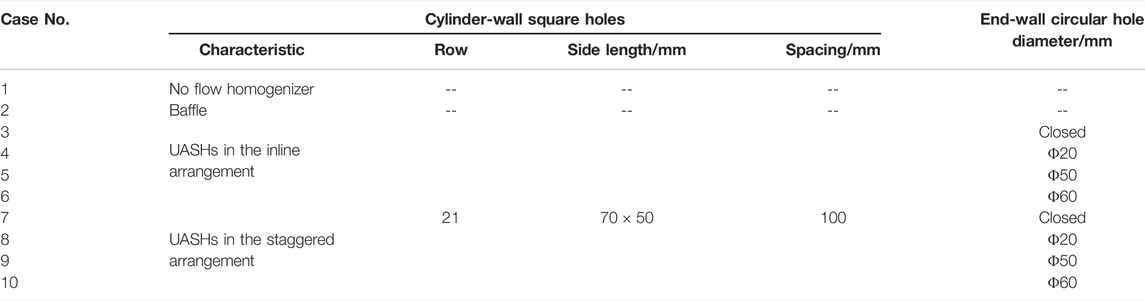
TABLE 3. Characteristic geometrical parameters of hot helium flow homogenizers with UASHs.
Table 4 presents the numerical results of inter-unit flow rate distribution, where the mass flow rate retains 4 significant digits. The number of the heat exchange unit is shown in Figure 2B.
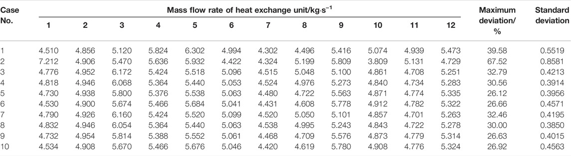
TABLE 4. Numerical results of inter-unit flow rate distribution of flow homogenizers with UASHs.
Compared with the No.3 and 7 inlet structures, the standard deviation of that without the flow homogenizer (No.1) is evidently large. Blocked by the main steam header, a large amount of hot helium flows down into the heat exchange unit under it. Hence, the maximum flow rate occurs within the No.5 heat exchange unit, the farthest from the primary-side hot helium inlet. Since the hot helium flowing upward is constrained by the top of the inlet structure, an annular flow appears downward along the side wall of the upper chamber. Therefore, the hot helium flow rate distributed within the heat exchange units (Nos. 6, 9, and 12) at the edge area is relatively large. Corresponding to the inter-unit flow rate distribution, the pressure of heat exchange units at the edge area is lower than that at the center area. The above conclusions are similar to the published literature (Zhang et al., 2011). The flow homogenizer not only avoids the direct impact of primary-side hot helium on the main steam header but also helps to improve inter-unit flow rate uniformity. In consideration of the significant flow uniformization effect, the hot helium flow homogenizer designed in this work can be a potential solution to improve temperature uniformity of the HTGR OTSG.
As the current structure design, a baffle is installed between the primary-side hot helium inlet and main steam header, which also plays a pivotal role in improving inter-unit flow rate uniformity. By comparing with the baffle (No.2), the maximum deviations and standard deviations of hot helium flow homogenizers (No.3–10) decrease significantly. It is necessary to further optimize the current inlet structure.
In this section, the necessity of setting circular holes on the end wall is qualitatively assessed. A total of 163 circular holes are hollowed out on the end wall with a grid pitch of 80 mm. As shown in Figure 6, these circular holes are arranged symmetrically.
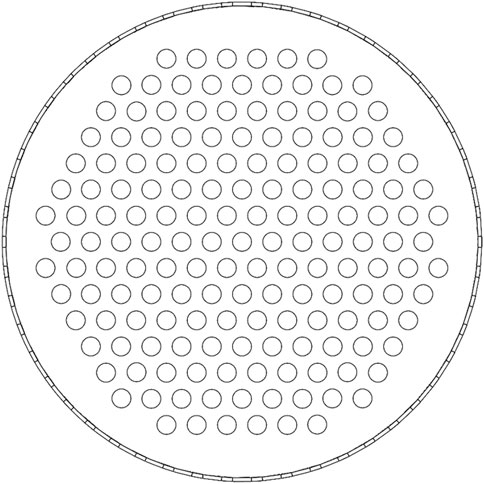
FIGURE 6. Arrangement of circular holes on the end wall.
From Table 4, the circular holes on the end wall have a significant impact on inter-unit flow rate distribution. The standard deviations of flow homogenizers (Nos. 4, 5, and 6 and 8, 9, and 10) with circular holes on the end wall are less than those with the closed end wall (Nos. 3 and 7). As a result, setting circular holes on the end wall is advantageous for improving inter-unit flow rate uniformity. Taking two flow homogenizers (Nos. 3 and 5) as examples, the flow fields are analyzed in detail. The surface streamlines, flow velocity, and pressure contours on the longitudinal section (stream-wise direction) are illustrated in Figure 7.
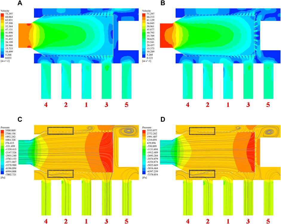
FIGURE 7. Velocity and pressure fields. (A) Flow velocity contour of No.3. (B) Flow velocity contour of No.5. (C) Pressure contour of No.3. (D) Pressure contour of No.5.
From Figures 7A,B, due to the continuous shunt flow from each row of square holes, the mainstream flow velocity decreases gradually in the flow homogenizer. The circular holes on the end wall are conductive to the smooth outflow of primary-side hot helium from the flow homogenizer. As shown in Figures 7C,D, corresponding to the variation of flow velocity, the static pressure gradually increases along the stream-wise direction. With the same cross-sectional area of the heat exchange unit, the streamlines can indirectly characterize inter-unit flow rate distribution. Figure 7C shows that the closed end wall allows hot helium to flow out only from the nearby square holes. Consequently, a lot of hot helium flows into the No.3 heat exchange unit below the end wall, while the flow rate of that at the edge area is relatively small. However, in Figure 7D, part of hot helium flows into the narrow gap through end-wall circular holes and then diffuses to the edge area. It increases the flow rate of heat exchange units blocked by the main steam header such as Nos. 5 and 9, which can improve inter-unit flow rate uniformity. Meanwhile, the performance of inter-unit flow rate distribution still depends on the specific circular hole diameter. When the circular holes are larger than 50 mm (Nos. 6 and 10), a further increasing diameter even aggravates inter-unit flow rate non-uniformity. In general, setting circular holes on the end wall can improve inter-unit flow rate uniformity, but the diameter should be less than 50 mm.
There are two types of square hole arrangement, that is, inline arrangement and staggered arrangement. As for the staggered arrangement, two adjacent rows of square holes on the cylinder wall are laterally staggered by 3.6°. These two arrangements are drawn in Figure 8.
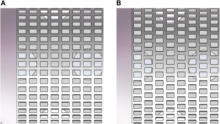
FIGURE 8. Square hole arrangement. (A) Inline arrangement. (B) Staggered arrangement.
For the hot helium flow homogenizers with the same circular holes but different square hole arrangements (Nos. 3 and 7, 4 and 8, 5 and 9, and 6 and 10 in Table 4, respectively), the maximum deviation and standard deviation are basically consistent with each other. As there is no change in the hot helium flow area, the square hole arrangement has little effect on inter-unit flow rate distribution. Further comparison indicates that the uniformity evaluation parameters of staggered arrangement are less than that of inline arrangement. To a certain extent, this staggered arrangement can conduce to inter-unit flow rate uniformity, which is applied in the follow-up investigations.
One limitation of the hot helium flow homogenizer with UASHs is that the improvement of inter-unit flow rate uniformity is still insufficient. Compared with the No.1 inlet structure, the maximum deviation of the hot helium flow homogenizer with UASHs decreases by less than 15%. Thus, its structure needs to be further optimized. Four flow homogenizers (Nos. 4 and 5 and 8 and 9, respectively) are chosen as examples, where their flow distribution characteristics are shown in Figure 9.
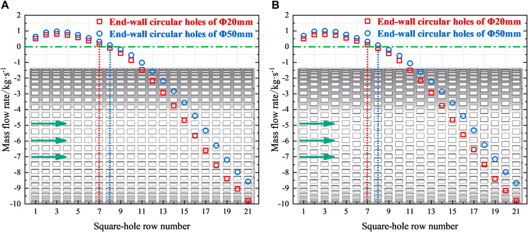
FIGURE 9. Flow distribution characteristics of flow homogenizers with UASHs. (A) Inline arrangement (Nos. 4 and 5). (B) Staggered arrangement (Nos. 8 and 9).
From Figure 9, it is found that the hot helium flow homogenizers in different square hole arrangements have almost similar flow distribution characteristics. Along the stream-wise direction, the positive mass flow rate of the first 8 rows means that hot helium flows into the flow homogenizer from the upper chamber. Subsequently, it becomes negative from the 9th row of square holes, which implies that hot helium flows out of the flow homogenizer. It is important to highlight that hot helium in some square holes near the primary-side hot helium inlet (referred to as near the inlet side) cannot outflow, whereas the helium in the upper chamber flows back into the flow homogenizer. As shown in the black dotted regions of Figures 7C,D, the streamlines also clearly exhibit this suction phenomenon. It can result in a remarkable inclination of flow distribution to the side away from the primary-side hot helium inlet (referred to as away from the inlet side), which deteriorates inter-unit flow rate uniformity. As the end-wall circular hole diameter decreases, the square holes where hot helium changes from the inflow to the outflow gradually move toward the inlet side. In brief, the effective improvement of inter-unit flow rate uniformity relies on whether hot helium can realize the outflow from all the rows of square holes. For the representative flow homogenizer (No.5), Figure 10 presents two enlarged velocity vectors to demonstrate the flow detail of the suction phenomenon.
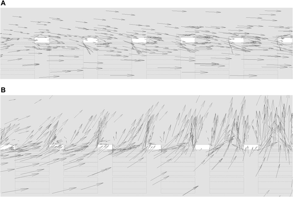
FIGURE 10. Local velocity vector of the flow homogenizer with UASHs. (A) Near the inlet side. (B) Away from the inlet side.
These vectors clearly show that the hot helium flow direction is opposite within the square holes near the inlet side and away from the inlet side. In Figure 10A, the velocity vectors are basically parallel to the mainstream flow direction. In the upper chamber, the hot helium near the square holes is gently sucked into the flow homogenizer. From Figure 10B, the velocity vectors are disordered, with the sharp change in flow velocity. A part of hot helium collides with the end wall of the flow homogenizer and reverses the flow direction. Along with the incoming flow, it flows out of the flow homogenizer through the square holes away from the inlet side.
As for the hot helium flow homogenizer with UASHs, the suction phenomenon appears at some square holes near the inlet side, resulting in the insufficient improvement of inter-unit flow rate uniformity. An acceptable explanation of the suction phenomenon is the negative static pressure difference caused by dynamic pressure. Figures 7C,D show that the external static pressure of the flow homogenizer is basically the same, while the internal static pressure gradually increases along the stream-wise direction. Their combined effect induces the gradual increase in static pressure difference. It is also the reason why the mass flow rate within each row of square holes gradually increases. Near the inlet side, the large dynamic pressure causes the internal static pressure to be lower than the external static pressure.
The improvement effect of the hot helium flow homogenizer on inter-unit flow rate uniformity depends on its own geometrical parameters. Further structure optimization should be carried out to suppress the suction phenomenon near the inlet side. It is a constructive optimization strategy to adjust the square holes on the cylinder wall to the non-uniform arrangement.
To address the limitation of improving inter-unit flow rate uniformity, the hot helium flow homogenizer with non-uniformly arranged square holes (NUASHs) is designed in this section. Specifically, there are more rows of square holes near the inlet side with large flow area and dense arrangement, while there are fewer rows of square holes away from the inlet side, with sparse arrangement and small flow area. In the structure design of the hot helium flow homogenizer, many geometrical parameters are coupled with each other, which cannot be completely decoupled. Therefore, the geometrical parameter effects on inter-unit flow rate uniformity are investigated in turn according to their significance.
To avoid excessive vibration, the minimum diameter of a circular hole should be above 20 mm. The pitches between two adjacent rows of square holes near the inlet side and away from the inlet side are defined as Pnear and Paway, respectively. For the flow homogenizers with different end-wall circular hole diameters, the characteristic geometrical parameters are listed in Table 5.
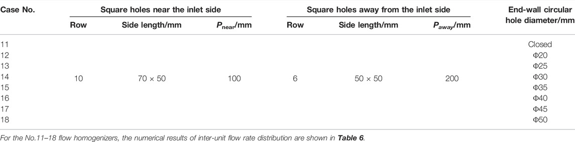
TABLE 5. Characteristic geometrical parameters of flow homogenizers with different end-wall circular hole diameters.
By comparing Table 4 and Table 6, it implicates that the hot helium flow homogenizer with NUASHs has better performance than that with UASHs in improving inter-unit flow rate uniformity. It is also confirmed that the structure optimization strategy clarified in Section 3.1.5 is feasible. However, the relatively limited variation of standard deviation suggests that the end-wall circular hole diameter has little effect on inter-unit flow rate uniformity. In summary, the large-scale adjustment of inter-unit flow rate distribution should still be achieved by changing the geometrical parameters of square holes on the cylinder wall, while the circular hole diameter is more suitable for the fine-tuning of flow distribution. Furthermore, the effect of end-wall circular hole diameter on inter-unit flow rate uniformity reports a strong coupling with other geometrical parameters. When the diameter is larger than 40 mm (Nos. 17 and 18), its flow uniformization effect is even inferior to the No.11 flow homogenizer with the closed end wall. With the decrease in end-wall circular hole diameter, the inter-unit flow rate uniformity improves gradually. As for the No.12 flow homogenizer, the optimal diameter is determined as 20 mm, which has the smallest standard deviation. The flow distribution characteristics of the above flow homogenizers with different end-wall circular hole diameters are illustrated in Figure 11.
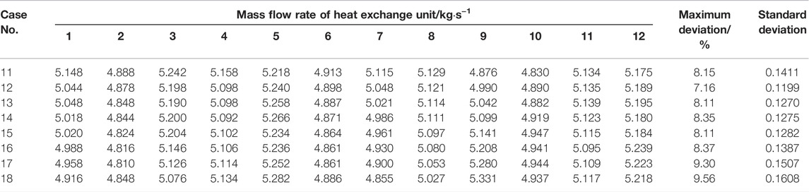
TABLE 6. Numerical results of inter-unit flow rate distribution for flow homogenizers with different end-wall circular hole diameters.
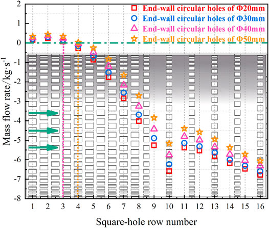
FIGURE 11. Flow distribution characteristics of flow homogenizers with different end-wall circular hole diameters.
As shown in Figure 11, these flow homogenizers with NUASHs realize the hot helium outflow from the 4th row of square holes. Compared with the flow homogenizers with UASHs, the square holes where hot helium changes from the inflow to the outflow have been obviously advanced. However, the suction phenomenon is still not effectively suppressed within the first 4 rows of square holes near the inlet side.
Square holes on the cylinder wall constitute the main flow channels for hot helium outflow from the flow homogenizer, whose geometrical parameters decisively influence inter-unit flow rate uniformity. Square hole row number is the most important parameter in determining the hot helium flow area on the cylinder wall. Several hot helium flow homogenizers with different row numbers have been designed. Table 7 shows their characteristic geometrical parameters.
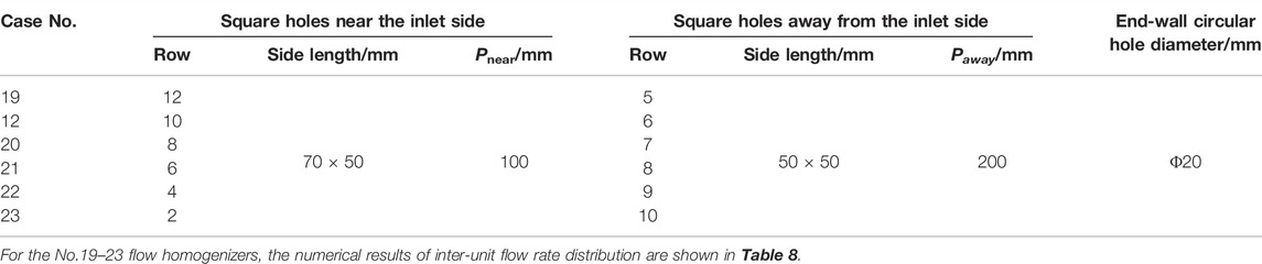
TABLE 7. Characteristic geometrical parameters of flow homogenizers with different square hole row numbers.
From Table 8, the standard deviation of the No.21 flow homogenizer is below 0.1, with 6 and 8 rows of square holes near the inlet side and away from the inlet side, respectively. It is the optimal row number determined in this section. For the cases where the square holes near the inlet side are less than 6 rows, the flow area away from the inlet side is larger than the other side, which means that the square hole arrangement tends to be uniform again. As the response to this flow area variation on both sides, the inter-unit flow rate uniformity deteriorates slightly. From above discussions, one may conclude that the flow area ratio of square holes on both sides should be within an appropriate range, to improve inter-unit flow rate uniformity. Taking the flow homogenizers (Nos. 19, 12, 20, and 23) as examples, their flow distribution characteristics are shown in Figure 12.
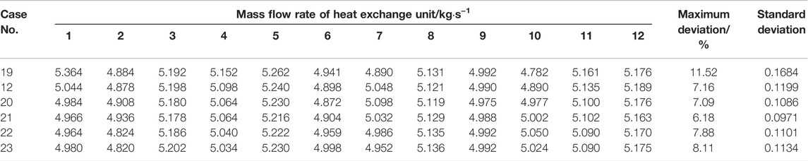
TABLE 8. Numerical results of inter-unit flow rate distribution for flow homogenizers with different square hole row numbers.
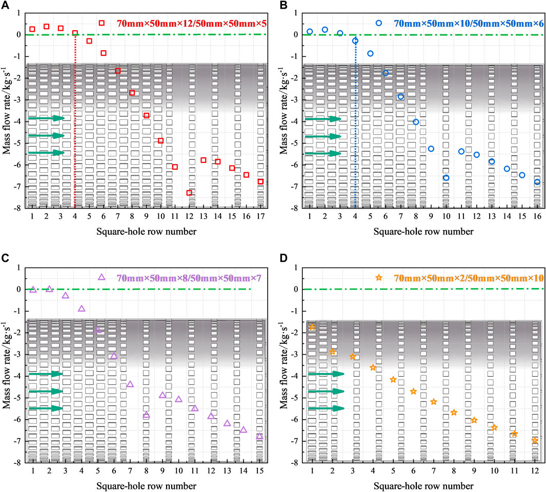
FIGURE 12. Flow distribution characteristics of flow homogenizers with different square hole row numbers. (A) Flow homogenizer No.19. (B) Flow homogenizer No.12. (C) Flow homogenizer No.20. (D) Flow homogenizer No.23.
Seen from Figure 12, with the decrease in row number near the inlet side, the square holes that realize the hot helium outflow from the flow homogenizer gradually moves forward. It implies that the suction phenomenon near the primary-side hot helium inlet tends to be sufficiently suppressed. Furthermore, the flow rate difference at the junction of square holes on both sides decreases gradually, and the curve of flow distribution characteristics also tends to be smooth. As shown in Figure 12C, hot helium can flow out of the No.20 flow homogenizer from all the rows of square holes. Not only is the suction phenomenon effectively suppressed but also the inter-unit flow rate distribution is more uniform. From Figure 12D, the No.23 flow homogenizer has the least row number (2 rows) of square holes near the inlet side, where the suction phenomenon is more significantly suppressed. There is more hot helium outflow from the first 2 rows of square holes than that of Figure 12C. In fact, the flow area ratio of square holes on both sides is reduced to the minimum value in this case. For the No.23 flow homogenizer, the square holes away from the inlet side are dominant, with the gradual transition of flow distribution characteristics to that with UASHs. The above analysis reveals that the suction phenomenon can be effectively suppressed within the appropriate range of the flow area ratio. This appropriate range can be approached by changing other geometrical parameters of square holes on the cylinder wall.
Square hole number in a single row is another important parameter to determine the hot helium flow area on the cylinder wall. With the above optimal end-wall circular hole diameter and square hole row number, five flow homogenizers with different square hole numbers are shown in Table 9.
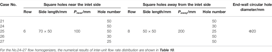
TABLE 9. Characteristic geometrical parameters of flow homogenizers with different square hole numbers in a single row.
Table 10 shows that decreasing the square hole number is disadvantageous to inter-unit flow rate uniformity. By further comparison of flow homogenizers (Nos. 21, 24, and 25 and 21, 26, and 27, respectively), the inter-unit flow rate uniformity is more sensitive to the square hole number away from the inlet side. The single row of 50 square holes on both sides is a better choice for the structure design of the flow homogenizer. Their flow distribution characteristics are shown in Figure 13.
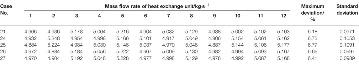
TABLE 10. Numerical results of inter-unit flow rate distribution for flow homogenizers with different square hole numbers in a single row.
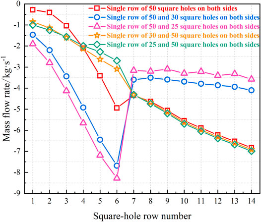
FIGURE 13. Flow distribution characteristics of flow homogenizers with different square hole numbers in a single row.
With the decrease in square hole number near the inlet side, the flow distribution characteristics of corresponding flow homogenizers (Nos. 21, 26, and 27) are roughly similar to each other, as shown by the red, green, and orange curves in Figure 13. However, the red, blue, and pink curves show the remarkable change in flow distribution characteristics, as the square hole number away from the inlet side decreases. These comparisons also reflect that the inter-unit flow rate distribution is more sensitive to the flow area away from the inlet side. This flow area sensitivity is attributed to the asymmetrical structure of the hot helium flow homogenizer. To increase the flow rate of heat exchange units blocked by the main steam header, the flow distribution characteristics of the flow homogenizer should still be slightly inclined to the side away from the primary-side hot helium inlet.
The square hole size can also influence the hot helium flow area on the cylinder wall. As shown in Table 11, seven flow homogenizers with different square hole sizes are investigated in this section, while other geometrical parameters remain exactly the same.
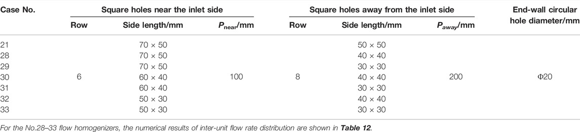
TABLE 11. Characteristic geometrical parameters of flow homogenizers with different square hole sizes.
Through comprehensive analysis for Tables 8, 10, 12, the square hole size can only slightly influence inter-unit flow rate distribution, compared with other geometrical parameters. The flow homogenizers (Nos. 21, 28, 30, 32, and 33) all have the excellent inter-unit flow rate uniformity, with the standard deviations below 0.1. Part of the reason is that the effect of square hole size on the hot helium flow area is much smaller than row number and square hole number. In addition, the flow area ratios corresponding to the flow homogenizers with different square hole sizes are covered within the above-mentioned appropriate range. From the view of the minimum standard deviation, the optimal size is considered as the square holes near the inlet side of 60 mm × 40 mm and that away from the inlet side of 40 mm × 40 mm, respectively. The flow distribution characteristics of the above flow homogenizers are shown in Figure 14.
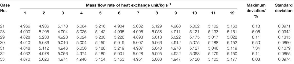
TABLE 12. Numerical results of inter-unit flow rate distribution for flow homogenizers with different square hole sizes.
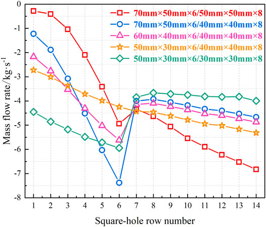
FIGURE 14. Flow distribution characteristics of flow homogenizers with different square hole sizes.
Similar to the previous discussions in Section 3.2.3, the flow distribution characteristics of the flow homogenizer are more sensitive to the hot helium flow area away from the inlet side, as inferred in Figure 14.
The optimal geometrical parameters of the hot helium flow homogenizer are summarized. A total of 163 circular holes are symmetrically arranged on the end wall with a grid pitch of 80 mm and diameter of 20 mm. On the cylinder wall, the square holes should be arranged non-uniformly, including 6 rows near the inlet side with a pitch of 100 mm and side length of 60 mm × 40 mm and 8 rows away from the inlet side with a pitch of 200 mm and side length of 40 mm × 40 mm, respectively. Moreover, the optimal square hole number should be 50 in each row. As for this hot helium flow homogenizer, the standard deviation of inter-unit flow rate distribution is only 0.0850, with the maximum inter-unit flow rate deviation being below 5.50%. Figure 15 presents the flow characteristics of the No.30 flow homogenizer with the optimal geometrical parameters.
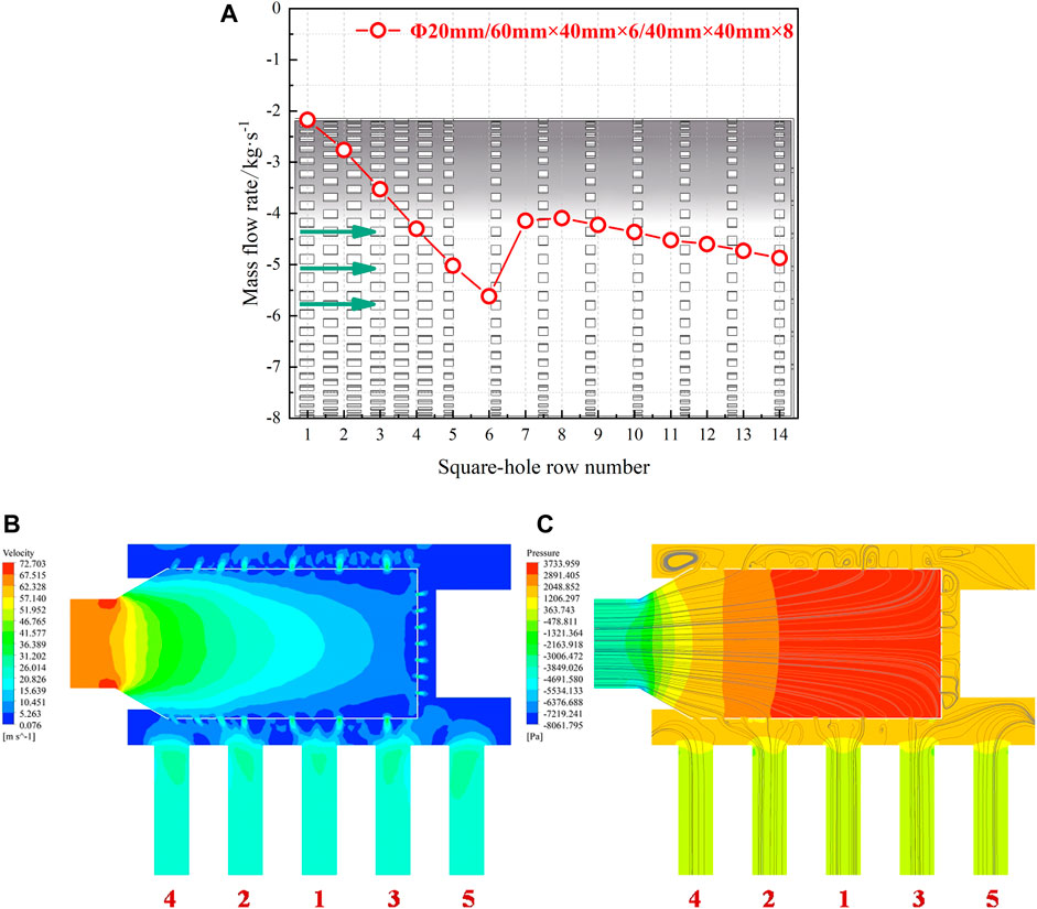
FIGURE 15. Flow characteristics of the optimal hot helium flow homogenizer (No.30). (A) Flow distribution. (B) Flow velocity contour. (C) Pressure contour.
From Figure 15A, the suction phenomenon is effectively suppressed, and the streamlines in Figure 15C also clearly show that hot helium realizes the outflow from all the rows of square holes. Meanwhile, the streamlines are uniformly distributed within each heat exchange unit, demonstrating the uniform inter-unit flow rate distribution. In terms of this flow homogenizer, the distributions of flow velocity and pressure provide a key link to the sufficient improvement of inter-unit flow rate uniformity. Thanks to the increased resistance through a specific structure design, the reduction of flow velocity within the flow homogenizer increases the internal static pressure. It ensures that the internal static pressure is always greater than the external static pressure, thereby reducing the effect of static pressure difference caused by dynamic pressure.
The inter-unit flow rate distribution is strongly associated with the geometrical parameters of the hot helium flow homogenizer, which directly determine its resistance coefficient. Therefore, the inter-unit flow rate uniformity can be viewed as the function of the resistance coefficient. The suction phenomenon is widely presented in the Nos. 3–19 hot helium flow homogenizers, while it can be effectively suppressed within other flow homogenizers (Nos. 20–33). In fact, the effective suppression of the suction phenomenon has a direct correlation with the resistance coefficient of the flow homogenizer.
According to the different mechanisms, the energy loss of viscous fluid can be divided into the friction and local resistance loss, where the pressure drop and resistance coefficient satisfy the following Darcy–Visbach formula (Darcy, 1857). The hot helium flow homogenizer is simplified as a throttle based on the idea of equivalent substitution, so its resistance coefficient can be calculated by local energy loss (Qin et al., 2019; Qin et al., 2020).
The Darcy–Visbach formula of local energy loss is as follows:
The resistance coefficient represents the overall flow characteristics of the flow homogenizer, but it cannot reflect the non-uniform arrangement of square holes on the cylinder wall. As a vital design parameter of the hot helium flow homogenizer with NUASHs, the flow area ratio of square holes on both sides (k) is introduced to depict the geometrical parameter effects on inter-unit flow rate uniformity, as calculated by Eq. 6.
where Fnear and Faway are the hot helium flow area of square holes near the inlet side and away from the inlet side, respectively. Similarly, fnear and faway are the flow area of a single square hole on both sides.
The inter-unit flow rate uniformity is principally evaluated based on the standard deviation, taking into account the maximum deviation. Considering the overall thermal hydraulic performance of the HTGR OTSG, the uniformity design requirement is established as the standard deviation below 0.1. The design parameters of the hot helium flow homogenizer which meets this uniformity design requirement are listed in Table 13.
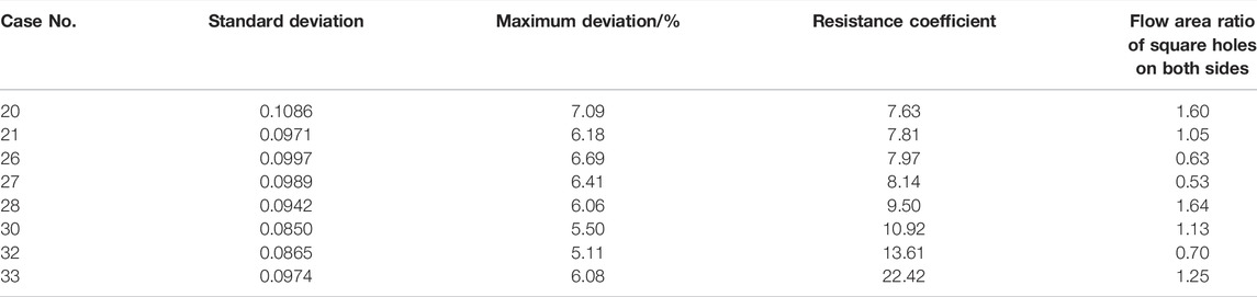
TABLE 13. Design parameters of the hot helium flow homogenizer.
From Table 13, the critical resistance coefficient is 7.63 for effective suppression of the suction phenomenon. As the optimized design of the new inlet structure, the hot helium flow homogenizer with NUASHs should be adopted to improve inter-unit flow rate uniformity of the HTGR OTSG. Meanwhile, it is recommended that the resistance coefficient and flow area ratio need to be controlled within the ranges of (7.81–22.42) and (0.53–1.64), respectively.
The resistance of the heat exchange unit is much greater than that of the inlet structure. It is necessary to verify the overall flow rate distribution of the full-scale HTGR OTSG. In these simulations, 19 heat exchange units are coupled with the inlet structure. The geometrical models of overall numerical simulation are shown in Figure 16.
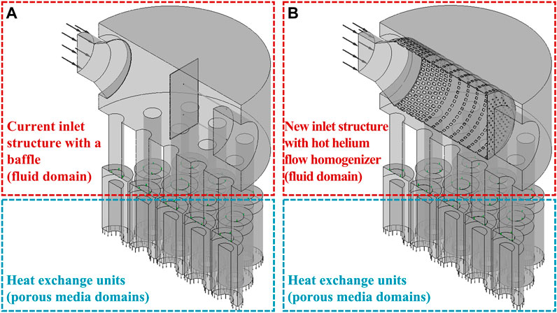
FIGURE 16. Geometrical model of the HTGR OTSG. (A) Current inlet structure with a baffle. (B) New inlet structure with the flow homogenizer.
Engineering verification experiment of the HTR-PM shows that the measured pressure drop of the heat exchange unit is 45 kPa, at a rated mass flow rate of 5.053 kg/s (Li et al., 2021). As for overall numerical simulation, the average pressure drop of 19 heat exchange units is 45.35 kPa, with a relative error of 0.77%. It is evident that the numerical results are in good agreement with previous experiment data. The reliability of numerical methods adopted in the current investigation is also validated. Table 14 shows the numerical results of overall flow rate distribution.
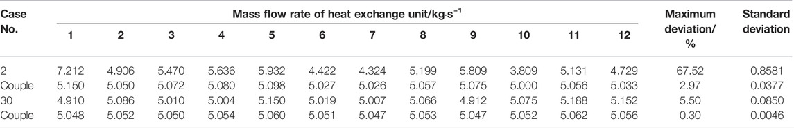
TABLE 14. Numerical results of overall flow rate distribution for the HTGR OTSG.
As shown in Table 14, the flow uniformization effect of the hot helium flow homogenizer is much more excellent than that of the current inlet structure with a baffle, with the maximum deviation decreased from 2.97% to 0.30%. It proves the feasibility of this new inlet structure of the hot helium flow homogenizer designed in this work.
Due to the high working temperature of the HTGR OTSG, large temperature non-uniformity should be avoided during operation. The primary-side helium flow rate distribution among the heat exchange units induced by the inlet structure is important for inter-unit temperature uniformity. A new inlet structure design with the hot helium flow homogenizer is proposed to improve inter-unit flow rate uniformity. Its flow distribution characteristics and mechanism are numerically investigated. Finally, the overall flow rate distribution of the HTGR OTSG is further evaluated by coupling the inlet structure and 19 heat exchange units. The main conclusions are as follows:
(1) Setting circular holes on the end wall can increase the flow rate of heat exchange units blocked by the main steam header, which can improve inter-unit flow rate uniformity.
(2) Flow distribution characteristics are strongly related with the geometrical parameters of square holes on the cylinder wall. The non-uniform arrangement is a more superior design for improving inter-unit flow rate uniformity, which can reduce the effect of static pressure difference caused by dynamic pressure.
(3) Increasing the resistance of the hot helium flow homogenizer can make the internal pressure greater than the external pressure, and the suction phenomenon near the inlet side can be effectively suppressed. The critical resistance coefficient is 7.63. Moreover, the resistance coefficient and flow area ratio are recommended to be within the ranges of (7.81–22.42) and (0.53–1.64), respectively.
(4) Compared with the previous baffle design, the hot helium flow homogenizer with NUASHs can reduce the maximum deviation from 2.97% to 0.30%, which is a promising design to further optimize the inlet structure of the HTGR OTSG.
The raw data supporting the conclusion of this article will be made available by the authors, without undue reservation.
HQ: methodology, software, design, validation, investigation, data curation, writing—original draft, and writing—review and editing. XLu: design, project administration, and supervision. XLi: methodology, design, theorization, writing—review and editing, and resources. XW: supervision and resources.
This work was financially supported by the National Key Research and Development Program of China (2020YFB1901600), the National Natural Science Foundation of China (51576103), and the National S&T Major Project (Grant No. ZX06901).
The authors declare that the research was conducted in the absence of any commercial or financial relationships that could be construed as a potential conflict of interest.
All claims expressed in this article are solely those of the authors and do not necessarily represent those of their affiliated organizations, or those of the publisher, the editors, and the reviewers. Any product that may be evaluated in this article, or claim that may be made by its manufacturer, is not guaranteed or endorsed by the publisher.
Mathews, A. J. 1987. “The Early Operation of the Helical Once-Through Boilers at Heysham 1 and Hartlepool,” In Proceeding of specialists’ meeting on technology of steam generator for gas-cooled reactors, Switzerland.
ANSYS (2019). ANSYS CFX-Solver Modeling Guide. Release 19.2. Available at: http://www.ansys.com (Accessed November 8, 2011).
ASME (2015). ASME Boiler and Pressure Vessel Code Section Ⅲ: Rules for Construction of Nuclear Facility Components. New York: ASME.
da Silva, B. L., Luciano, R. D., Utzig, J., and Meier, H. F. (2019). Analysis of Flow Behavior and Fluid Forces in Large Cylinder Bundles by Numerical Simulations. Int. J. Heat Fluid Flow 75, 209–226. doi:10.1016/j.ijheatfluidflow.2019.01.006
Darcy, H. (1857). Researches Experimentales Relatives Au Mouvement De L’eau Dans Les Tuyaux. Paris, France: Mallet-Bachelier 1857
Gao, W. K. (2020). Numerical and Experimental Investigation on the Flow and Heat Transfer Non-uniformity of Cross Flow over Tube Bundles (Doctor Thesis). Beijing, PR China: Tsinghua University.
Gao, W., Li, X., Wu, X., Zhao, J., and Luo, X. (2020). Influences of Fabrication Tolerance on Thermal Hydraulic Performance of HTGR Helical Tube once through Steam Generator. Nucl. Eng. Des. 363, 110665. doi:10.1016/j.nucengdes.2020.110665
Gao, W., Zhao, J., Li, X., Zhao, H., Zhang, Y., and Wu, X. (2019). Heat Transfer Characteristics of Carbon Dioxide Cross Flow over Tube Bundles at Supercritical Pressures. Appl. Therm. Eng. 158, 113786. doi:10.1016/j.applthermaleng.2019.113786
Generation-Ⅳ International Forum (2002). A Technology Roadmap for Generation Ⅳ Nuclear Energy Systems. Report No.: GIF-002-00. Available at: https://www.hsdl.org/?view&did=894 (Accessed December 12, 2002).
Hayat, T., Haider, F., Alsaedi, A., and Ahmad, B. (2021). Entropy Generation Analysis of Carreau Fluid with Entire New Concepts of Modified Darcy's Law and Variable Characteristics. Int. Commun. Heat Mass Transf. 120, 105073. doi:10.1016/j.icheatmasstransfer.2020.105073
Iacovides, H., Launder, B., and West, A. (2014). A Comparison and Assessment of Approaches for Modelling Flow over In-Line Tube Banks. Int. J. Heat Fluid Flow 49, 69–79. doi:10.1016/j.ijheatfluidflow.2014.05.011
Idelchik, I. E., and Fried, E. (2016). Handbook of Hydraulic Resistance. New York: Begell House Inc.
Kong, L. (2014). Engineering Fluid Mechanics. 4th Edn. Beijing, PR China: China Electric Power Press.
Li, X., Gao, W., Su, Y., and Wu, X. (2019b). Thermal Analysis of HTGR Helical Tube once through Steam Generators Using 1D and 2D Methods. Nucl. Eng. Des. 355, 110352.doi:10.1016/j.nucengdes.2019.110352
Li, X. W. (2012). Thermal-hydraulic and Temperature Sensitivity Analysis of the HTR-PM once through Steam Generator. Beijing, China: Institute of Nuclear and New Energy Technology. (internal report).
Li, X., Wu, X., and He, S. (2014). Numerical Investigation of the Turbulent Cross Flow and Heat Transfer in a Wall Bounded Tube Bundle. Int. J. Therm. Sci. 75, 127–139. doi:10.1016/j.ijthermalsci.2013.08.001
Li, X., and Wu, X. (2013). Thermal Mixing of the Cross Flow over Tube Bundles. Int. J. Heat Mass Transf. 67, 352–361. doi:10.1016/j.ijheatmasstransfer.2013.08.031
Li, X. W., Wu, X. X., and Luo, X. W. (2016). “Thermal Hydraulic Issues of HTGR Helical Tube once through Steam Generator: Methods and Application,” in The 8th International Topical Meeting on High Temperature Reactor Technology (HTR-2016) (NV: Las Vegas).
Li, X. W., Wu, X. X., Zhang, Z. Y., Zhao, J., and Luo, X. (2021). Engineering Test of HTR-PM Helical Tube once through Steam Generator. J. Tsinghua Univ. Sci. Technol. 61, 329–337. (in Chinese).
Li, X. W., Wu, X. X., and Zhang, Z. Y. (2019a). Thermal Hydraulics of HTGR Helical Tube once through Steam Generator. Atomic Energy Sci. Technol. 53, 1906–1917. (in Chinese). doi:10.7538/yzk.2019.53.10.1906
Olson, J. T., Li, X., and Wu, X. (2014). Tube and Shell Side Coupled Thermal Analysis of an HTGR Helical Tube once through Steam Generator Using Porous Media Method. Ann. Nucl. Energy 64, 67–77. doi:10.1016/j.anucene.2013.09.036
Qin, H., Lu, D., Liu, S., Tang, J., Wang, Y., and Zhong, D. (2019). Hydraulic Experiment Investigation on the Plate-Throttle Entry Tube Flow Characteristics of Fast Reactor Fuel Assembly. Nucl. Eng. Des. 352, 110172. doi:10.1016/j.nucengdes.2019.110172
Qin, H., Lu, D., Zhong, D., Wang, Y., and Song, Y. (2020). Experimental and Numerical Investigation for the Geometrical Parameters Effect on the Labyrinth-Seal Flow Characteristics of Fast Reactor Fuel Assembly. Ann. Nucl. Energy 135, 106964. doi:10.1016/j.anucene.2019.106964
Satter, A., and Iqbal, G. M. (2016). Fundamentals of Fluid Flow through Porous Media. Reserv. Eng., 155–169. doi:10.1016/b978-0-12-800219-3.00009-7
Tao, W. Q. (2017). Numerical Heat Transfer. 2nd Edn. Xi’an, PR China: Xi'an Jiaotong University Press.
Wu, Z., Lin, D., and Zhong, D. (2002). The Design Features of the HTR-10. Nucl. Eng. Des. 218, 25–32. doi:10.1016/s0029-5493(02)00182-6
Wu, Z. X., and Zhang, Z. Y. (2000). World Development of Nuclear Power System and High Temperature Gas-Cooled Reactor. Chin. J. Nucl. Sci. Eng. 20 (3), 211–219. (in Chinese). doi:10.3321/j.issn:0258-0918.2000.03.004
Zhang, J., Li, X. W., and Wu, X. X. (2011). Numerical Investigation of the HTR-PM Steam Generator Entrance Structure Influence to the Flow Distribution. Chin. High. Technol. Lett. 21, 652–656. (in Chinese). doi:10.3772/j.issn.1002-0470.2011.06.016
Zhang, Z., Dong, Y., Li, F., Zhang, Z., Wang, H., Huang, X., et al. (2016). The Shandong Shidao Bay 200 MW e High-Temperature Gas-Cooled Reactor Pebble-Bed Module (HTR-PM) Demonstration Power Plant: An Engineering and Technological Innovation. Engineering 2, 112–118. doi:10.1016/j.eng.2016.01.020
Zhang, Z., and Sun, Y. (2007). Economic Potential of Modular Reactor Nuclear Power Plants Based on the Chinese HTR-PM Project. Nucl. Eng. Des. 237, 2265–2274. doi:10.1016/j.nucengdes.2007.04.001
Zhang, Z., Wu, Z., Wang, D., Xu, Y., Sun, Y., Li, F., et al. (2009). Current Status and Technical Description of Chinese 2×250MWth HTR-PM Demonstration Plant. Nucl. Eng. Des. 239, 1212–1219. doi:10.1016/j.nucengdes.2009.02.023
Zhao, H., Li, X., and Wu, X. (2017). Numerical Investigation of Supercritical Water Turbulent Flow and Heat Transfer Characteristics in Vertical Helical Tubes. J. Supercrit. Fluids 127, 48–61. doi:10.1016/j.supflu.2017.03.016
Zhou, Y., Hao, P., Li, F., Shi, L., He, F., Dong, Y., et al. (2016). Experiment Study on Thermal Mixing Performance of HTR-PM Reactor Outlet. Nucl. Eng. Des. 306, 186–191. doi:10.1016/j.nucengdes.2016.03.009
Zhou, Y. P., Li, F., Hao, P. F., and He, F. (2011). Similarity Analysis for Hot Gas Mixing Experiment of Outlet of HTR-PM Reactor Core. Atomic Energy Sci. Technol. 45, 1208–1214. (in Chinese).
A cross-sectional area (m2)
c local acoustic velocity (m/s)
Cp specific heat capacity at constant pressure (J/(kg·K))
d helical tube outer diameter (m)
f hot helium flow area of a single hole (m2)
F hot helium flow area (m2)
k flow area ratio of square holes on both sides, dimensionless
K permeability (m2)
L length (m)
Ma Mach number, dimensionless
p pressure (Pa)
∆p pressure drop (Pa)
P pitch (m)
Qv volume flow rate (m3/s)
Re Reynolds number, dimensionless
S1 transverse tube pitch (m)
S2 stream-wise tube pitch (m)
T temperature (°C)
v flow velocity (m/s)
y+ dimensionless wall distance
γ thermal expansivity (/K)
η dynamic viscosity (Pa·s)
λ thermal conductivity (W/(m·K))
ξ resistance coefficient, dimensionless
ρ density (kg/m3)
σ standard deviation, variable unit
away away from the inlet side
near near the inlet side
Keywords: high temperature gas-cooled reactor, once through steam generator, inlet structure, hot helium flow homogenizer, inter-unit flow rate uniformity
Citation: Qin H, Luo X, Li X and Wu X (2022) Numerical Investigation of Hot Helium Flow Homogenizer on Inter-Unit Flow Rate Uniformity of HTGR Once Through Steam Generator. Front. Energy Res. 10:925380. doi: 10.3389/fenrg.2022.925380
Received: 21 April 2022; Accepted: 20 May 2022;
Published: 07 July 2022.
Edited by:
Luteng Zhang, Chongqing University, ChinaReviewed by:
Ehsan Rafiee, Urmia University of Technology, IranCopyright © 2022 Qin, Luo, Li and Wu. This is an open-access article distributed under the terms of the Creative Commons Attribution License (CC BY). The use, distribution or reproduction in other forums is permitted, provided the original author(s) and the copyright owner(s) are credited and that the original publication in this journal is cited, in accordance with accepted academic practice. No use, distribution or reproduction is permitted which does not comply with these terms.
*Correspondence: Xiaowei Li, bGl4aWFvd2VpQHRzaW5naHVhLmVkdS5jbg==
Disclaimer: All claims expressed in this article are solely those of the authors and do not necessarily represent those of their affiliated organizations, or those of the publisher, the editors and the reviewers. Any product that may be evaluated in this article or claim that may be made by its manufacturer is not guaranteed or endorsed by the publisher.
Research integrity at Frontiers
Learn more about the work of our research integrity team to safeguard the quality of each article we publish.