 Muhammad Usman
 Ali H. Kazim
 Aqsa Shabbir2*
 Muhammad Salman Abbasi
95% of researchers rate our articles as excellent or good
Learn more about the work of our research integrity team to safeguard the quality of each article we publish.
Find out more
ORIGINAL RESEARCH article
Front. Energy Res. , 25 July 2022
Sec. Solar Energy
Volume 10 - 2022 | https://doi.org/10.3389/fenrg.2022.917419
This article is part of the Research Topic Energy Materials Based Novel Solar Thermal Applications View all 13 articles
This work deals with different design configurations using existing photon recycling technologies such as front spectral filters and back surface reflectors (BSRs) to improve the efficiency of the thermophotovoltaic (TPV) cells. On the TPV cell surface, some photons absorb, but some quantity of them is lost due to the interference on the surface. On the other hand, BSR mounted on the backside of the cell reflects all photons which were not absorbed by TPV back to the front side of the cell and the emitter, which leads to the elevated temperature of the cell and more interference on the cell surface. This work aimed to design a configuration of the TPV system model using hybrid photon recycling technologies and to investigate the efficiencies of different TPV cells with numerous factors such as emitter temperature and reflectivity of the spectral filter. The design parameters and configuration of front filters with BSRs are studied under 2500 K temperature of the emitter. It is found that an InGaAs cell with reasonable bandgap energy of 0.72 eV, is the most favorable cell material as its bandgap wavelength (1.68 μm) is closely matched to the peak wavelength (1.65 μm) of the emissions spectra. The results show that the incorporation of magnesium oxide (MgO) spectral filter along with the BSR (R = 1) and the emitter temperature of 2200 K efficiency as high as 35% can be attained. This makes MgO a viable choice in TPV cell system under concentrated solar power plant.
The global energy crisis has increased due to the depletion of natural resources to meet the energy demands of the planet (Coyle and Simmons, 2014). Many countries use fossil fuels such as coal and natural gas, while some others use water and nuclear resources to generate electricity (Cherp et al., 2017; Onifade et al., 2021). Over the centuries, fossil fuels have been used for energy as they are an economical resource to rely on, for energy production. But they come up with the global warming problem which further leads to the problem of sea-level rise, fires, storms, and massive floods. Due to this, there is an increased interest in deploying renewable energy resources to meet the energy demand of the planet instead of relying solely on limited natural resources such as fossils (Romero et al., 2012; Li et al., 2014; Güney, 2019; Hansen et al., 2019). The extreme consumption of these resources is responsible for environmental degradation (Hank et al., 2020). The solution to these problems lies in the fact that renewable energy resources should be used instead of non-renewables for power generation (Hansen et al., 2019). As reported, by 2050, two out of three global energy demands will be met by renewable resources (Goorha and Denemark, 2010).
Wind and solar renewable energy resources are examples of renewable energy resources, but they are not dependable as they depend on weather conditions (Barber, 2018; Jung et al., 2018; Warren et al., 2018; Cendula et al., 2019). However, increased research in the field of renewable energy resources can help overcome this problem (Kazim et al., 2020). Concentrated solar power (CSP) uses focused Sun rays to generate electrical power and is widely used nowadays. Concentrated solar power also faces a lot of the irradiation at their surface due to which efficiency is decreased as irradiation is increased (Chen et al., 2016a). We cannot extract photons from the CSP as they cannot be stored for a longer period (Kazim et al., 2020). Thermophotovoltaics (TPVs) can be used in addition to the CSP, as it converts solar radiation to an intermediate form of energy (Boriskina et al., 2015). TPV is composed of a system that converts the electromagnetic radiation source from a heated body to the electrical power through photovoltaics (Datas and Vaillon, 2021). Renewable energy resources like thermophotovoltaics (TPVs) have emerged over the last decade to replace fossil fuels. Although there are many modern fossil plants that use combined cycle power plants to decrease the heat waste. Current CSP combined cycles have an efficiency of about 35–40% (Henry et al., 2014). TPV conversion of this heat waste into electricity is a promising technology. A TPV technology takes the heat from the heat source of the CSP, and this heat energy is further converted into electrical energy. TPV paired with CSP also utilizes lesser area for equipment (Seyf et al., 2016). TPV has extremely high reliability, low noise, high gravimetric, and long operation time advantages. TPV cells use a variety of heat sources such as chemical, nuclear, solar, and waste heat, which heats up radiators commonly known as emitters whose temperatures go up to 1,300–2,000 K (Nelson, 2003).
A CSP-TPV combined power cycle is shown in Figure 1 which explains the Sun ray incident on the heliostats of the concentrated solar power plant which direct rays toward the secondary concentrators which focus them on the heating tower. In the heating tower, the heat transfer fluid (HTF) changes its phase and then melts the metal to be stored in the thermal energy storage for further use. The electrical power output, efficiency, and incident radiations of a TPV module are calculated using MATLAB. Secondary sources receive the reflected Sun rays from heliostats. The heat transfer fluid (HTF) heats up via the secondary collectors and goes to the thermal energy storage (TES) where it cools down and gets pumped back to repeat the cycle (Kazim et al., 2020). The schematic diagram in Figure 2 shows the energy and temperature conversion of the system in which overall flow chart of Sun rays to electrical output is shown. T and Tmelt represent the temperature of the graphite emitter pipes and the temperature of the phase change material (PCM). The TES stores the thermal energy by melting the PCM via the heat of the HTF and maintains the temperature of the HTF that must enter the TPV cycle. Under high partial shading conditions (PSC), the HTF does not attain a temperature high enough to melt the PCM, now when HTF passes from the TES the PCM releases energy and heats up the HTF. Valves are fitted in the system to maintain the unidirectional flow of the HTF as they prevent the HTF from flowing back to the TES and collectors from the TPV power cycle (Kazim et al., 2020). Many other solar thermal conversion and thermal energy storage of phase change composites materials are used such as CuO/paraffin (Chen et al., 2019). The TPV power cycle consists of a hexagonal cell cavity that is surrounded by water and a filter, TPV cells, and a BSR enclosed in a graphite pipe. Graphite has a high emissivity value (>0.90) (Midilli et al., 2006) which makes them a good choice for use in these pipes. Most of the research that has been conducted utilizes the flat vertical plate TPV cell used in between emitter pipes. The hexagonal cavity used as its view factor is the same as that of the circular pipes (Yuksel et al., 2015). The performance of the TPV cells varies with the effect of temperature and radiations wavelengths that fall onto its surface, which is why most of the TPV cell arrays are equipped with spectral controls such as back surface reflectors (BSRs) and spectral filters as most of the emissions from the back body are below the bandgap (Rahmlow et al., 2007). The cell also receives the emission spectrum from the emitter which leads to the feverish temperature of the cell. Filters are used to improve the efficiency by removing any below-bandgap photons from the emission spectra of the emitter. The spectral filters are placed between the emitter and the TPV cell as they filter the photons that are below the bandgap of the TPV cell back to the emitter and let pass the higher bandgap photons as is (Rahmlow et al., 2004; Rahmlow et al., 2007; Chirumamilla et al., 2019). The photons with energy lower than the bandgap of the TPV cell cannot play part in transitions so they are filtered beforehand to reduce any interference at the surface of the cell and to keep the cell temperature lower (Rahmlow et al., 2007). On a TPV cell’s surface, photons are absorbed, but some quantity of them is lost due to the interference on the surface. BSR is placed behind the TPV cells (Kazim et al., 2020). BSR mounted on the backside of the cell reflects the unabsorbed photons that are passed unabsorbed from the cell back to the active area of the TPV cell for the reabsorption which helps in increased efficiencies (Datas and Vaillon, 2021). BSR also reflects the below-bandgap photons back to the emitter and the emitter temperature is increased which improves the efficiency of the system (Wang et al., 2003). The specifications of the single-junction InGaAs (McClelland and Mankin, 2018) cells that are used in a TPV array are such that the top contact layer of InGaAs is 0.025 μm thick, which is followed by an emitter layer that is 0.1 μm thick. The other three layers are as follows, the InGaAs base layer, InP buffer layer, and the InP substrate layer which are 2.5, 0.3, and 625 μm thick, respectively (Kazim et al., 2020).
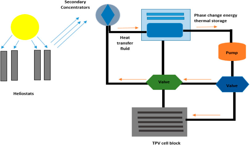
FIGURE 1. Design of CSP-TPV combined power cycle. Secondary concentrators receive the sun rays through heliostats, which melt the HTF (molten tin, and Sn) and transfer it to the TES where it melts the PCM (silicon, Si). The TPV cell block contains graphite which explains the sun rays incident on the heliostats of the concentrated solar power plant which direct rays toward the secondary concentrators which focus them on the heating tower. In the heating tower, the heat transfer fluid (HTF) changes its phase and then melt the metal to be stored in the thermal energy storage for further use.
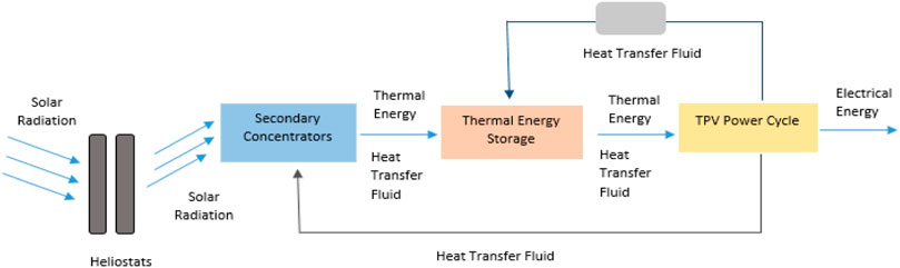
FIGURE 2. Schematic diagram of a combined CSP-TPV power cycle shows the energy and temperature conversion of the system in which overall flow chart of sun rays to electrical output is shown.” The block diagram shows the principle of energy transformation in the discussed configuration of a CSP plant with a TPV power cycle.
The thermophotovoltaic systems are not much efficient without any spectral control, and they have only a fraction of energy converted to electricity which is 16–18% approximately (Ferrari et al., 2014). There is a potential in improving the conversion efficiencies of TPV systems by optimizing the TPV device’s design, design of the cavity, and other fabrication configurations which include the use of multilayer TPV cells, BSRs, and spectral filters (Phan et al., 2009). Wavelength-selective emitters achieve better TPV performance than Ti and Ni filters. The nanoparticle material–based emitters show suitable results with low bandgap PV cells (Chen et al., 2021). It has also been observed with high refractive index materials such as antimony selenide, antimony sulfide, and gallium telluride as a spectral filter in TPV which possibly achieve 20% efficiency at a temperature of 363.15 K for a 0.6 eV band of cell (Rahmlow et al., 2007). The TPV cell of the GaSb cell using the waste heat recovery with the spectral technology of the front filter at the operating temperature of 1,300–3,100 K was found to be 21.57% energy conversion efficiency (Utlu, 2020). Wernsman et al. (2004) calculated the efficiency with the use of the back surface reflector which is 23.6%. Another configuration is used in the back surface reflector which is known as the hybrid back surface reflector GaInAsSb TPV device. In this configuration, the GaInAsSb-based TPV cell is constructed and a surface reflector is mounted on the backside which has the potential of recirculating the infrared photons which further helps to improve the efficiency (Huang et al., 2004). For InGaAs cell of 0.74 eV, the recent study attained more than 15% TPV efficiency which becomes more than 30% with reflectivity of 100% which made TPV favorable for concentrated solar power plants at a temperature of emitter more than 2,000 K (Kazim et al., 2020). The aforementioned techniques are commonly used in TPV to increase efficiency, but up to an extent. There must be further improvements needed to work on TPV as it has significant room for improvements, unlike other solid-state heat engines which are currently operating at their thermodynamic limits as compared to other heat engines.
This study is based on efficiency enhancement with the combination of spectral controls, that is, the use of spectral filters along with existing photon recycling technologies such as BSR to improve the efficiency of the TPV system beyond 30%. Before this only front filters or back surface reflectors were used to recycle the photons, but in this study, the front filter is used to stop the low bandgap photons which create the interference on the surface of the TPV cell. This technique reduces the interference on the TPV cell which also decreases the temperature reducing the waste heat which is lost in cooling the cell. Furthermore, the use of spectral filters will maintain the temperature of the cell, lesser energy will be utilized for cooling the cells and they also suppress the amount of interference on the surface of the cell by removing lower bandgap photons from the emission spectra and hence achieve better efficiencies than only BSRs (Isobe et al., 2020; Sergeev and Waits, 2020). It also includes the investigation of factors such as EQE, emitter temperature, back surface reflectors, and spectral filters on the efficiency of the TPV cell. Section 2 includes the materials that can be used for TPV cells, losses in a TPV system, and the use of different spectral control techniques. Section 3 presents the methodology followed throughout the study, which is followed by Section 4 which outlines the results and accompanying discussion. Section 5 concludes the study.
The photovoltaic cells that are used in a TPV system use single-junction cells, but a multijunction cell can also be used (Datas and Cells, 2015). Many cells are compared in this study, which includes silicon (Si), germanium (Ge), silicon–germanium (SiGe), gallium antimonide (GaSb), indium gallium arsenide (InGaAs), indium gallium arsenide antimonide (InGaAsSb), gallium arsenide (GaAs), cadmium telluride (CdTe) (Midilli et al., 2006). Silicon-based TPV models have been used for many years, as Si has a bandgap of 1.12 eV at 300 K. Si has a single-crystal structure and belongs to the IV group. Ge has the lower bandgap energy of 0.66 eV and their conversion efficiency is 6.7%, these cells show poor performances and are used in multijunction solar converters. BSRs are usually feasible for the Ge cells as their major challenge is the high voltage factor (Kazim et al., 2020). SiGe cells can have an altered bandgap in between the range of 0.66 and 1.12 eV, and this bandgap can be tuned with the change in the composition of the cell (Pethuraja et al., 2012). InGaAs (InxGa1-xAs) cells can have a bandgap ranging from 0 to 1 by changing the stoichiometry (i.e., the value of x) of the cells (Cabrera et al., 2018). GaSb cells have a conversion efficiency of 3% which can be improved to 18%. These cells have a bandgap of 0.72 eV and are the best choice for TPV generators. InGaAsSb has the tunable bandgaps and the lattice constants (Midilli et al., 2006) GaAs and CdTe have high absorptivity which allows us to use a layer of only a few microns (Kazim et al., 2020).
The efficiency of TPV systems is reduced due to many practical losses, which can be enhanced by improving the components of the system (Seyf et al., 2016). These losses include the thermalization losses (Heidarzadeh et al., 2020) which are caused when the energy in the emission spectra is much higher than the energy of the bandgap and this also results in the heating of the cell. Non-absorption losses occur when the opposite happens, and the bandgap energy is higher than the energy in the emission spectra (Boulkhrachef, 2019). In other words, the emission spectra from the emitter consist of low bandgap photons that cannot take part in transitions and hence generate electrical power (Rahmlow et al., 2007).
These lower bandgap photons also create interference when they collide with the high bandgap photons at the surface of the cell. Due to this interference, much of the useful photon flux passes through the cell and goes without absorption, and energy is lost (Rahmlow et al., 2007). On the other hand, if the cell absorbs these lower bandgap photons they also result in additional heating of the cell and more energy is lost in the cooling of the TPV cell (Rahmlow et al., 2007). The reflective losses occur because photons get reflected from the top layer and due to the large emitter–cell distance they are not reabsorbed, and the transmission losses occur because of the cell’s layer thickness (Nicholas and Tuley, 2012; Bernardi et al., 2015). Other losses also include radiative and non-radiative recombination losses which result in the recombination of the generated electron-hole pair and a photon, and a phonon are released, respectively, based on the properties of the cell’s material (Yu and Zunger, 2012).
A TPV cell should be paired with photon recycling technologies to minimize the mentioned losses. Photon recycling refers to the methods in which only the photons that can be converted to the useful electrical power are allowed to reach the TPV cell and the non-convertible photons are suppressed and not able to reach the cell’s surface (Rahmlow et al., 2007). This is also referred to as spectral control and there are different approaches to control the spectra. The cell should be placed close to the emitter to have the least edge effect and the view factor of nearly 1. The bandgap of a TPV cell should be closely matched to the blackbody radiation of the emitter and the peak wavelength of the spectrum so that a major part of the incoming photon flux is converted to electrical power (Rahmlow et al., 2007). The selective emitters emit the spectrum in a specific wavelength region when they are heated (Sakakibara et al., 2019). The selection of emitter material that allows such suppressive emissions is difficult and should be the cost-effective option. These emitters are composed of photonic crystals and rare earth metals (Sakr et al., 2014; Wang et al., 2014; Zhou et al., 2016a; Kim et al., 2018). Another method for spectral control is to add the filters between the heat source and the cell. The longer wavelength (lower bandgap) photons included in the emission spectra of the emitter, create interference at the cell’s surface when they collide with the shorter wavelength (high bandgap) photons, and much of the useful photon flux passes unabsorbed from the cell (Rahmlow et al., 2007) and the temperature of the cell is also increased. Spectral filters do not transmit the below-bandgap (long wavelength) photons, from the incoming spectrum, and reflect them back to the heated body (Erdoğar et al., 2010; Chirumamilla et al., 2019). This way the lower energy photons are filtered before reaching the surface of the TPV cell and only high bandgap photons that can play part in transitions reach the cell. There is reduced optical loss due to interference at the surface of the cell and the temperature of the cell is not increased. Hence, less energy is lost in cooling the cell (Rahmlow et al., 2004; Rahmlow et al., 2007; Chirumamilla et al., 2019). The BSR, placed behind the TPV cell, reflects back low and high bandgap photons, that went unfiltered and unabsorbed from the cell, back to the emitter and the front face of the TPV cell, respectively (Kazim et al., 2020; Datas and Vaillon, 2021), which further improves the efficiency of the TPV systems. Figure 3 shows the schematic of the mentioned procedure and how the incorporation of both the spectral filters and BSRs in a TPV system enhances the number of useful spectra from the emitter. In Figure 3, emitters which are graphite rod are shown which emit the radiations and the front spectral filter of MgO which stops the low bandgap photons reaching on the TPV cell front side. The TPV cell is placed in between the front filter and back surface reflector, after the TPV cell back surface reflector is placed which reflects all the unabsorbed radiations back to the TPV front side. The back surface reflector is attached to the backside of the TPV cell which is also mounted with a cooling system which maintains the TPV cell temperature to 300 K.
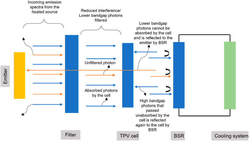
FIGURE 3. TPV system with hybrid photon recycling technologies includes spectral filter and BSR in which concept of filtering and reflecting photons back to the front side of the TPV cell is explained.
The TPV system including the photon recycling technologies is modeled using MATLAB. The configuration of the TPV system has been made with the basic spectral control technologies, that is , front filters and BSRs. The simulation was run by changing the different cell types such as silicon, germanium, and other cells, varying emitter temperature, and reflectivity of the filters. Then, the efficiency of the TPV cells is calculated and the parameters that influence the improvement of the TPV device’s efficiency are concluded. Figure 4 represents the mentioned procedure in the form of a flow chart which explains the TPV system is modeled using MATLAB which encounters the variables that stop the low bandgap photons from reaching the front surface of the TPV cell, and then BSR variables reflect the unabsorbed photons back to the front side of the TPV cell. In this manner, the efficiency of different cells by varying the emitter temperature and reflectivity of BSR is calculated.
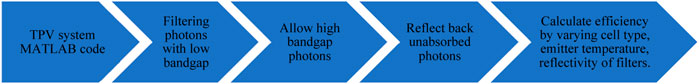
FIGURE 4. Flow chart representing the followed methodology which represents the mentioned procedure in the form of a flow chart which explains the TPV system is modeled using MATLAB which encounter the variables that stops the low bandgap photons reaching the front surface of TPV cell then BSR variables reflects the unabsorbed photons back to the front side of the TPV cell.
The emissions from the graphite emitter are given by the Plank distribution function for the black bodies (Pfiester and Vandervelde, 2017) and the factor
where
Wein’s displacement law given by Eq. 2 gives the value of the wavelength at which the emissive spectra is at its peak.
The aforementioned equation shows that there is an inverse relationship between the peak wavelength and the emitter temperature. The bandgap wavelength
where h is the Planck’s constant, c is the speed of light, and q is the charge of an electron in Coulombs. The photons above the bandgap region, which have a wavelength shorter than
The total emitted power of the spectrum is calculated as follows, where
As stated, it is essential to place an optical filter between the emitter and the TPV cell to enhance the efficiency conversion of the overall system. The filter must have low absorptance and be highly transmissive, and it should be able to transmit the photons that have energy greater than the bandgap energy of the cell
Similarly, it should have large reflectance for the photons that have energy lower than the bandgap energy of the cell
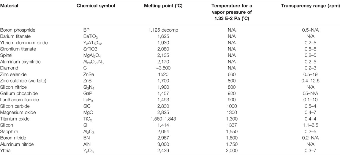
TABLE 1. Crystalline materials used as spectral filters along with their melting points.
Currently, no nanoparticles have the photostability, suitable wavelength transparency, and near-infrared emission specifically for the TPV cell of InGaAs (Khalid et al., 2019). Apart from these properties, the MgO spectral filter is stable under the temperature conditions of up to 2800 K. MgO contributes by filtering the photons up to 0.4 µm. Contrary to this, Y2O3 is another suitable choice due to its light composition and wide spectra in wavelength and high temperature resistivity (Zhou et al., 2016b; Lee, 2018).
BSRs are placed in the TPV systems behind the cell. They act as spectral control as they reflect back the low bandgap photons back to the emitter and they also help in improving the efficiency of the cell as they increase the intensity of the high bandgap photons at the active layer of the cell for the second pass absorption, that lie in the range of the cell (Wang et al., 2003; Kazim et al., 2020; Datas and Vaillon, 2021). BSRs must have high thermal stability and strong adhesion (Charache et al., 1996). Highly reflective materials with less absorbance, including metals like gold (Au) and silver (Ag) can be used as BSR (Machrafi, 2012; Datas and Cells, 2015; Chen et al., 2016b; Seyf et al., 2016; Karalis and Joannopoulos, 2017).
External quantum efficiency (EQE) tells the probability of photons that have been incident on the TPV cell absorbed by the cell and used in generating charge carriers (Ferrari et al., 2014) within the cell. The EQE of the photons with energy below the bandgap energy is zero. EQE is exclusively characteristic of the TPV cell device irrespective of the characteristics of the emitter (Kazim et al., 2020). Ideally, the EQE must be constant and equal to 1 but due to many losses that occur within the cell, radiative and non-radiative recombination losses are among those (Shockley and Queisser, 1961), the EQE shows an irregular behavior (Kazim et al., 2020).
The EQE data of the TPV cell can be determined experimentally or are also provided by the manufacturer of the cell. It is unique for all cells. Such an EQE plot for a 0.25 cm2 n-p InGaAs cell has been drawn in Figure 5, using the experimental data given by Tuley et al. (2012) and the equation mentioned.
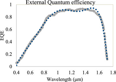
FIGURE 5. Experimentally measured data and curve of best fit for the 0.25 cm2 n-p InGaAs cell (Tuley et al., 2012).
The average external quantum efficiency
where
The double diode model is equivalent to the TPV system design used here, and it represents the voltage–current behavior of the system. The second diode incorporates the recombination losses in the depletion region (Jena et al., 2015). The equation gives the current–voltage characteristics (Hejri et al., 2014) of the model and Figure 6 represents the circuit diagram for the double diode model.
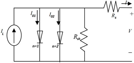
FIGURE 6. Double diode model equivalent to the TPV system (Jena et al., 2015).
The photon flux
The denominator in Eq. 10 denotes the average energy of photons from the emitter, and wavelengths ranging from
The dark saturation current
The dark saturation currents are calculated by simultaneously solving Eq. 12 using two sets of measured currents at the voltage values of
Figure 7 shows the IV characteristics of a 0.25 cm2 n-p InGaAs cell.
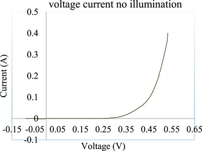
FIGURE 7. IV characteristics of a 0.25 cm2 n-p InGaAs cell were recorded in dark Tuley, 2012.
Fill factor
where
To find
The efficiency of the TPV system which includes back surface reflector and spectral filters with reflectivity R is given as follows (Scranton et al., 2016):
The aforementioned relation Eq. 17 shows how the efficiency of the system varies with the incorporation of photon recycling technologies. The output power of the cell remains the same but the effective energy at the input of the cell is decreased by the factor of the reflectivity of each spectral control technique incorporated. If only BSR is included in the system then the efficiency is enhanced to a certain extent, on the other hand, when filtering technology is incorporated along with the BSR (second term in the denominator), low energy photons are filtered, which further reduces the energy at the input by the factor of reflectivity R of the filter and hence the overall efficiency of the TPV system is enhanced. The efficiency of such hybrid TPV systems will always be greater than the systems which use single technology, that is, either spectral filter or BSR for photon recycling.
Table 2 shows different PV cell materials along with their bandgap energy
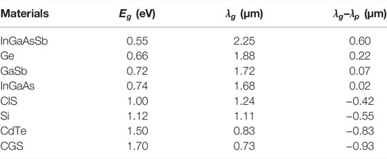
TABLE 2. Different PV cell materials are compared.
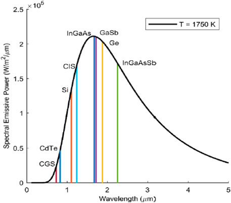
FIGURE 8. Distribution of spectral emissive power (W/m2/μm) against wavelength (μm) at an average emitter temperature of 1750 K.
It can be noted from Figure 8 that the CGS and CdTe cells have the lowest bandgap wavelengths and hence the lowest spectral emissive power region above the bandgap (
The selected filter must have a wide transparency range and high melting point because of the high emitter temperatures. FSS and TCO filters are not used as they are very costly and have high absorption near the plasma frequency, respectively. All-dielectric filters on the other hand show interference among different filter layers and have small wavelength ranges (Machrafi, 2012). Crystalline materials Y2O3 and MgO are used for filtering the low bandgap photons from the emission spectra of the emitter since these have a wide transmission range
The In0.53Ga0.47As grown on the InP substrate, the region of the spectral emissive power that is above the bandgap of InGaAs
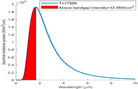
FIGURE 9. Curve shows the spectral emissive power distribution for a graphite emitter at a temperature of 1750 K, and ε = 0.91. The red shaded region is the emissive intensity, having energy above the bandgap energy (0.74 eV) for an InGaAs TPV cell.
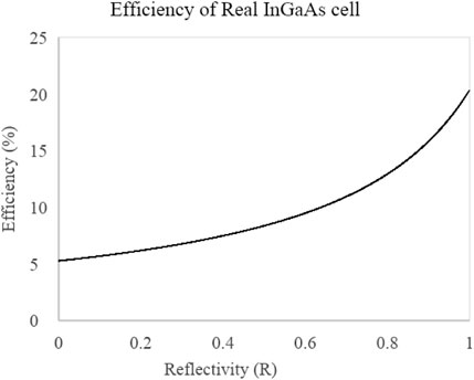
FIGURE 10. η of a real 0.25 cm2 InGaAs module (avg EQE = 0.7097) with respect to BSR reflectivity R for an emitter temperature of 1750 K. The efficiency of the module increases with the increasing R.
As can be seen from the graph in Figure 10, the efficiency of the TPV cell with absolutely no reflectivity (R = 0) is exceptionally low, that is, 5.5%. But as the reflectivity is increased to almost 1, the efficiency of the cell at the emitter temperature of 1750 K also increases and reaches almost 20.3% for a real TPV cell.
It has been recorded that the external quantum efficiency can be improved using a cell material that has a high coefficient of absorption (Wang et al., 2020), high reflective coatings at the back of the cell (BSR), and using textured front surface (Ray et al., 2015), using cells with lower bandgap energy that are composed of quantum nanostructures (Datas et al., 2017) and the use of multijunction or tandem cells can also improve the EQE (Moss et al., 2018). In this section, the efficiency of the real TPV cell (EQE
For an ideal TPV cell, the saturation currents
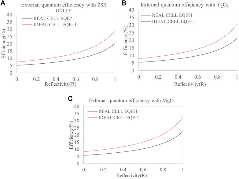
FIGURE 11. Efficiency of the real TPV module (EQE = 0.709) compared to the ideal TPV module (EQE = 1) for different photon recycling technologies (A) EQE with BSR only, (B) EQE with Y2O3 recorded at an emitter temperature of 1750 K, and (C) EQE with MgO.
As the temperature of the blackbody emitter is increased, the spectral emissive power and hence the photon flux above the bandgap is also improved which increases the photogenerated current (Machrafi, 2012). Hence, the increasing emitter temperature improves the efficiency of the TPV cell. Figure 12 shows the performance of the TPV cell with the use of BSR only as the emitter temperature is increased. The efficiency of the cell goes from 26.2% to 31.7% as the temperature is raised from 1400 to 2200 K. Figures 13A,B illustrate how the performance of the TPV cell is improved at elevated emitter temperatures as the spectral filters are incorporated along with the BSR with the increasing emitter’s temperature. The efficiency of the TPV cell that uses Y2O3 spectral filter with BSR at maximum reflectivity, R = 1 (Figure 13B) improves efficiency from 27 to 33.2% as the temperature goes from 1400 to 2200 K. Similarly, with MgO as the spectral filter used along with BSR (Figure 13A), the efficiency of the cell is further improved from 29 to 35% as the temperature is increased. This increase in the efficiencies is since the low energy bandgap photons and hence the interference at the surface of the cell is reduced with the incorporation of the filter and cell temperature is also maintained at 303 K. Hence, the efficiency of the TPV system is enhanced as the temperature of the emitter is elevated. The previous studies have shown that this increase in efficiency reaches 31.7% at 2200 K emitter temperature if only BSR is incorporated in the system (Kazim et al., 2020). However, if hybrid spectral optimization technologies are used, that is, BSR paired with front spectral filters, the efficiencies can be improved even further.
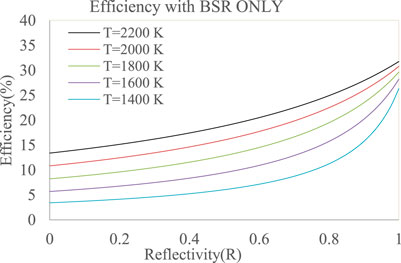
FIGURE 12. Effect of increasing emitter temperature on the efficiency (η) of a real 0.25 cm2 InGaAs TPV cell (avg EQE = 0.7097) with respect to the reflectivity R of the BSR. The efficiency of the cell increases with the increasing T.
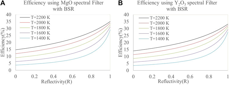
FIGURE 13. (A) BSR used along with the MgO spectral filter. The efficiency of the module increases with the increasing T. (B) Effect of increasing emitter temperature on the efficiency (η) of a real 0.25 cm2 InGaAs TPV cell (EQE = 0.7097) with respect to the reflectivity R of the BSR used along with the Y2O3 spectral filter.
Spectral control technologies have proven to enhance the efficiencies of the current TPV systems. Figures 14A–E demonstrate how different photon recycling technologies including BSR, MgO, and Y2O3 spectral filters, improve the overall efficiency of the cell at various emitter temperatures. The efficiency values at maximum reflectivity (R = 1), from Figures 14A–E are extracted and listed in tabular form in Table 3. The crystalline spectral filters are better than the BSRs and they can increase the efficiency of the cell much more than BSRs. The MgO spectral filter maximizes the efficiency improvement rather than Y2O3. The overall efficiency with MgO is 35% which is more than with the use of BSRs only, that is, 31.7% (Kazim et al., 2020). With MgO as the front filter at 2200 K there is an almost 3.3% efficiency increase while with Y2O3 as a filter, this increase is 1.4% more than the previous technique of BSR. This shows that there is quite a room for improvement in the efficiencies of the TPV systems with the incorporation of hybrid spectral controls.
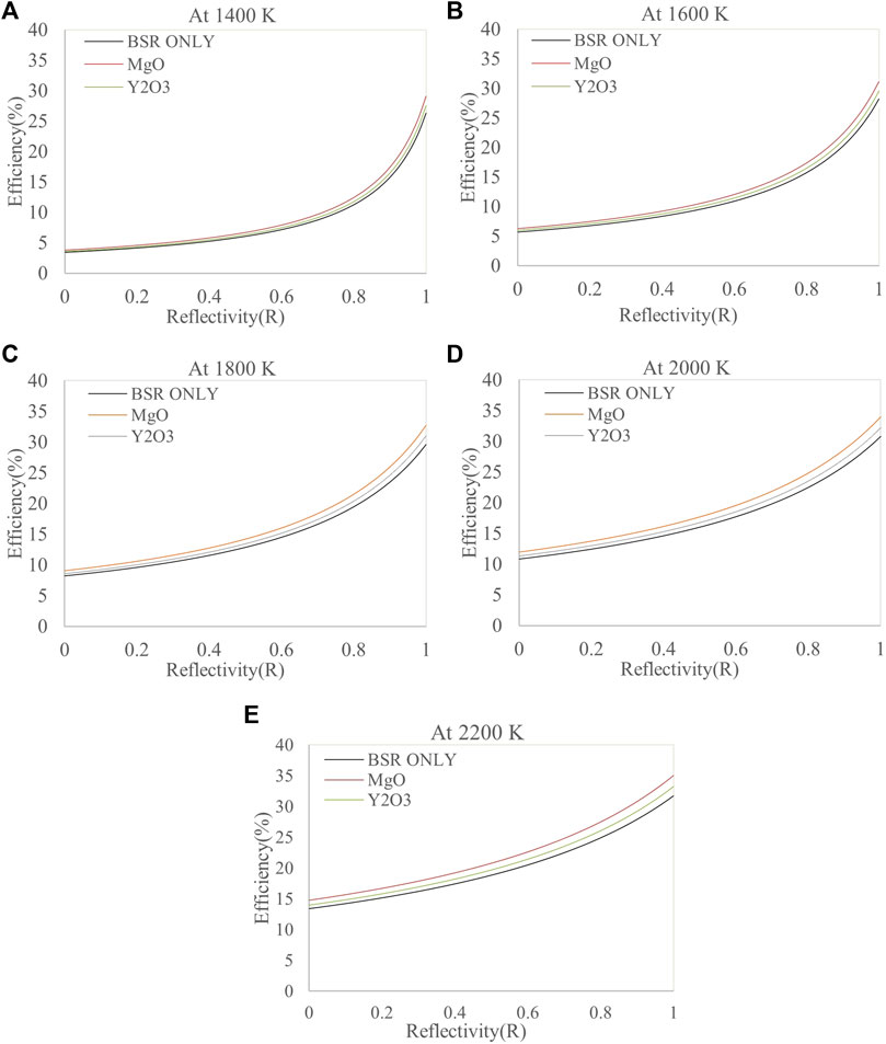
FIGURE 14. (A–E) Effect on efficiency improvement with BSR Only, Y2O3, and MgO spectral filters at the temperatures of 1400, 1600, 1800, 2000, and 2200 K.
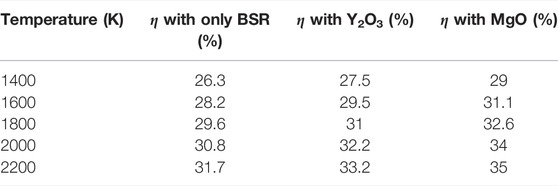
TABLE 3. Spectral technology–wise efficiency improvement; (η at the emitter temperatures of 1400, 1600, 1800, 2000, and 2200 K).
In this work, the design parameters and configuration of front filters with BSRs are studied under 2500 K temperature of the emitter. It is found that cells with moderate bandgap energy like Ge (0.66 eV), GaSb (0.72 eV), and InGaAs (0.74 eV) are most favorable as their bandgap wavelength is well-matched with the peak wavelength calculated through Wein’s law, in addition, they provide lower recombination rates and high photon flux above the bandgap region. It can be concluded that MgO is better than the Y2O3 spectral filter because with the use of the MgO front filter at 2200 K there is about a 3.3% efficiency increase while with the Y2O3 spectral filter used along with BSR, this increase is 1.4% than the previous technique of using BSR only. The overall efficiency attained with the proposed hybrid technique, that is, the use of MgO as a filter along with BSR, is 35% and this hybrid technique also helps in reducing the interference at the cell surface and maintaining the cell temperature at almost 303 K while acting as a heat shield between the emitter and the cell. Thus, with such improvements in research, TPV has the capability to replace the CSP plant turbine.
The raw data supporting the conclusion of this article will be made available by the authors, without undue reservation.
MU, AK, and AS were involved in experimentation and the other authors helped in data analysis and write up.
The authors declare that the research was conducted in the absence of any commercial or financial relationships that could be construed as a potential conflict of interest.
All claims expressed in this article are solely those of the authors and do not necessarily represent those of their affiliated organizations, or those of the publisher, the editors, and the reviewers. Any product that may be evaluated in this article, or claim that may be made by its manufacturer, is not guaranteed or endorsed by the publisher.
The Supplementary Material for this article can be found online at: https://www.frontiersin.org/articles/10.3389/fenrg.2022.917419/full#supplementary-material
Anjani, N. R. (2021). The Form of Jakarta-Berlin Paradiplomacy in Sister City Cooperation in the Field of Culture under International Relations.
Barber, J. (2018). Hydrogen Derived from Water as a Sustainable Solar Fuel: Learning from Biology. Sustain. Energy Fuels 2 (5), 927–935. doi:10.1039/c8se00002f
Bernardi, M. P., Dupré, O., Blandre, E., Chapuis, P. O., Vaillon, R., and Francoeur, M. (2015). Impacts of Propagating, Frustrated and Surface Modes on Radiative, Electrical and Thermal Losses in Nanoscale-Gap Thermophotovoltaic Power Generators. Sci. Rep. 5 (1), 11626. doi:10.1038/srep11626
Boriskina, S. V., Tong, J. K., Ferry, V., Michel, J., and Kildishev, A. (2015). Breaking the Limits of Optical Energy Conversion. Opt. Photonics News 26 (7), 48–51. doi:10.1364/opn.26.7.000048
Boulkhrachef, S. (2019). Higher-Order Sliding Mode Control of a Wind Energy Conversion System. Nonlinear Dyn. Syst. Theory 19 (4), 486–496.
Bouzid, F., and Dehimi, L. (2012). Performance Evaluation of a GaSb Thermophotovoltaic Converter. Rev. Des. Energies Renouvelables 15 (3), 383–397.
Breitenstein, O., Rißland, S., and cells, s. (2013). A Two-Diode Model Regarding the Distributed Series Resistance. Sol. Energy Mater. Sol. Cells 110, 77–86. doi:10.1016/j.solmat.2012.11.021
Cabrera, A., Ramos, A., Artacho, I., Gomez, M., Gavin, K., Martí, A., et al. (2018). “Thermophotovoltaic Efficiency Measurement: Design and Analysis of a Novel Experimental Method,” in 2018 Spanish Conference on Electron Devices (CDE) (Salamanca, Spain: IEEE). doi:10.1109/cde.2018.8596820
Cendula, P., Mayer, M. T., Luo, J., and Grätzel, M. (2019). Elucidation of Photovoltage Origin and Charge Transport in Cu2O Heterojunctions for Solar Energy Conversion. Sustain. Energy Fuels 3 (10), 2633–2641. doi:10.1039/c9se00385a
Charache, G., DePoy, D. M., Baldasaro, P. F., and Campbell, B. C. (1996). Thermophotovoltaic Devices Utilizing a Back Surface Reflector for Spectral Control. AIP Conf. Proc. 358, 339. doi:10.1063/1.49697
Chen, M., Chen, X., Yan, H., and Zhou, P. (2021). Theoretical Design of Nanoparticle-Based Spectrally Emitter for Thermophotovoltaic Applications. Phys. E Low-Dimensional Syst. Nanostructures 126, 114471. doi:10.1016/j.physe.2020.114471
Chen, M., He, Y., Huang, J., and Zhu, J. (2016). Synthesis and Solar Photo-Thermal Conversion of Au, Ag, and Au-Ag Blended Plasmonic Nanoparticles. Energy Convers. Manag. 127, 293–300. doi:10.1016/j.enconman.2016.09.015
Chen, M., He, Y., Ye, Q., Zhang, Z., and Hu, Y. (2019). Solar Thermal Conversion and Thermal Energy Storage of CuO/Paraffin Phase Change Composites. Int. J. Heat Mass Transf. 130, 1133–1140. doi:10.1016/j.ijheatmasstransfer.2018.11.026
Chen, M., He, Y., Zhu, J., and Wen, D. (2016). Investigating the Collector Efficiency of Silver Nanofluids Based Direct Absorption Solar Collectors. Appl. Energy 181, 65–74. doi:10.1016/j.apenergy.2016.08.054
Cherp, A., Vinichenko, V., Jewell, J., Suzuki, M., and Antal, M. (2017). Comparing Electricity Transitions: A Historical Analysis of Nuclear, Wind and Solar Power in Germany and Japan. Energy Policy 101, 612–628. doi:10.1016/j.enpol.2016.10.044
Chirumamilla, M., Krishnamurthy, G. V., Knopp, K., Krekeler, T., Graf, M., Jalas, D., et al. (2019). Metamaterial Emitter for Thermophotovoltaics Stable up to 1400 °C. Sci. Rep. 9 (1), 7241. doi:10.1038/s41598-019-43640-6
Coyle, E. D., and Simmons, R. A. (2014). Understanding the Global Energy Crisis. West Lafayette, Indiana, USA: Purdue University Press.
Datas, A., and Cells, S. (2015). Optimum Semiconductor Bandgaps in Single Junction and Multijunction Thermophotovoltaic Converters. Sol. Energy Mater. Sol. Cells 134, 275–290. doi:10.1016/j.solmat.2014.11.049
Datas, A., Martí, A., and Cells, S. (2017). Thermophotovoltaic Energy in Space Applications: Review and Future Potential. Sol. Energy Mater. Sol. Cells 161, 285–296. doi:10.1016/j.solmat.2016.12.007
Datas, A., and Vaillon, R. (2021). “Thermophotovoltaic Energy Conversion,” in Ultra-High Temperature Thermal Energy Storage, Transfer and Conversion (Amsterdam, Netherlands: Elsevier), 285–308. doi:10.1016/b978-0-12-819955-8.00011-9
Erdoğar, N., Mungan, A., and Bilensoy, E. (2010). Preparation and Characterization of Cationic Nanoparticles Loaded with Mitomycin C by Double Emulsion and Ionotropic Gelation Techniques. J. Control Release 148 (148), e78–9. doi:10.1016/j.jconrel.2010.07.015
Ferrari, C., Melino, F., Pinelli, M., Spina, P. R., and Venturini, M. (2014). Overview and Status of Thermophotovoltaic Systems. Energy Procedia 45, 160–169. doi:10.1016/j.egypro.2014.01.018
Goorha, P. (2010). “Modernization Theory,” in The International Studies Encyclopedia. Editor R. A. Denemark (Malden, Ma: Wiley-Blackwell).
Green, M. A., Emery, K., King, D. L., Igari, S., and Warta, W. (2003). Solar Cell Efficiency Tables (Version 22). Prog. Photovolt. Res. Appl. 11, 347–352. doi:10.1002/pip.499
Güney, T. (2019). Renewable Energy, Non-Renewable Energy and Sustainable Development. Int. J. Sustain. Dev. World Ecol. 26 (5), 389–397. doi:10.1080/13504509.2019.1595214
Hank, C., Sternberg, A., Köppel, N., Holst, M., Smolinka, T., Schaadt, A., et al. (2020). Energy Efficiency and Economic Assessment of Imported Energy Carriers Based on Renewable Electricity. Sustain. Energy Fuels 4 (5), 2256–2273. doi:10.1039/d0se00067a
Hansen, K., Breyer, C., and Lund, H. (2019). Status and Perspectives on 100% Renewable Energy Systems. Energy 175, 471–480. doi:10.1016/j.energy.2019.03.092
Heidarzadeh, H., Rostami, A., and Dolatyari, M. (2020). Management of Losses (Thermalization-Transmission) in the Si-QDs Inside 3C-SiC to Design an Ultra-High-Efficiency Solar Cell. Mater. Sci. Semicond. Process. 109, 104936. doi:10.1016/j.mssp.2020.104936
Hejri, M., Mokhtari, H., Azizian, M. R., Ghandhari, M., and Soder, L. (2014). On the Parameter Extraction of a Five-Parameter Double-Diode Model of Photovoltaic Cells and Modules. IEEE J. Photovoltaics 4 (3), 915–923. doi:10.1109/jphotov.2014.2307161
Henry, A., Prasher, R., and Science, E. (2014). The Prospect of High Temperature Solid State Energy Conversion to Reduce the Cost of Concentrated Solar Power. Energy Environ. Sci. 7 (6), 1819–1828. doi:10.1039/c4ee00288a
Hristov, H. D. (2016). “Fresnel Zone Plate Antenna,” in Handbook of Antenna Technologies (Berlin, Germany: Springer), 1187–1248. doi:10.1007/978-981-4560-44-3_42
Huang, R. K., Wang, C. A., Connors, M. K., Turner, G. W., and Dashiell, M. (2004). Hybrid Back Surface Reflector GaInAsSb Thermophotovoltaic Devices. AIP Conf. Proc. 738, 329. doi:10.2172/836454
Isobe, K., Okino, R., and Hanamura, K. (2020). Spectral Absorptance of a Metal-Semiconductor-Metal Thin-Multilayer Structured Thermophotovoltaic Cell. Opt. Express 28 (26), 40099–40111. doi:10.1364/oe.410828
Jena, D., Ramana, V. V., and Reviews, S. E. (2015). Modeling of Photovoltaic System for Uniform and Non-Uniform Irradiance: A Critical Review. Renew. Sustain. Energy Rev. 52, 400–417. doi:10.1016/j.rser.2015.07.079
Jung, K. W., Sohn, M. R., Lee, H. M., Yang, I. S., Sung, S. D., Kim, J., et al. (2018). Silver Bismuth Iodides in Various Compositions as Potential Pb-Free Light Absorbers for Hybrid Solar Cells. Sustain. Energy Fuels 2 (1), 294–302. doi:10.1039/c7se00477j
Karalis, A., and Joannopoulos, J. D. (2017). Transparent and ‘opaque' Conducting Electrodes for Ultra-Thin Highly-Efficient Near-Field Thermophotovoltaic Cells. Sci. Rep. 7 (1), 14046. doi:10.1038/s41598-017-13540-8
Kazim, A. H., Asif, M., Nadeem, K., Shoukat, Z., Nazir, R., Malik, M. S., et al. (2020). Efficiency Enhancement of a Thermophotovoltaic System Integrated with a Back Surface Reflector. IEEE Access 8, 153226–153239. doi:10.1109/access.2020.3017504
Khalid, A., Norello, R., N. Abraham, A., Tetienne, J.-P., J. Karle, T., W. C. Lui, E., et al. (2019). Biocompatible and Biodegradable Magnesium Oxide Nanoparticles with In Vitro Photostable Near-Infrared Emission: Short-Term Fluorescent Markers. Nanomaterials 9 (10), 1360. doi:10.3390/nano9101360
Kim, J. M., Park, K. H., Kim, D. S., Hwang, B. Y., Kim, S. K., Chae, H. M., et al. (2018). Design and Fabrication of Spectrally Selective Emitter for Thermophotovoltaic System by Using Nano-Imprint Lithography. Appl. Surf. Sci. 429, 138–143. doi:10.1016/j.apsusc.2017.07.300
Köstlin, H. (1982). Application of Thin Semiconductor and Metal Films in Energy Technology. Adv. Solid State Phys. 22, 229–254.
Lee, E. (2018). Synthesis and Luminescence Properties of Bi3+, Yb3+ Co-Doped Y2O3 Phosphor Powder and Thin Film for Application in Solar Cells. Bloemfontein, SA: University of the Free State.
Lenert, A., Bierman, D. M., Nam, Y., Chan, W. R., Celanović, I., Soljačić, M., et al. (2014). A Nanophotonic Solar Thermophotovoltaic Device. Nat. Nanotech. 9 (2), 126–130. doi:10.1038/nnano.2013.286
Li, H., Yu, Y., Niu, F., Shafik, M., and Chen, B. (2014). Performance of a Coupled Cooling System with Earth-To-Air Heat Exchanger and Solar Chimney. Renew. Energy 62, 468–477. doi:10.1016/j.renene.2013.08.008
Machrafi, H. (2012). Philosophy for Controlling Auto-Ignition in an HCCI Engine. Green Energy Technol. 2012, 323–366. doi:10.2174/978160805285111201010323
McClelland, A., and Mankin, M. (2018). Optical Measurements for Scientists and Engineers: A Practical Guide. Cambridge: Cambridge University Press.
Meyer, E. L. (2017). Extraction of Saturation Current and Ideality Factor from Measuring Voc and Isc of Photovoltaic Modules. Int. J. Photoenergy 2017, 8479487. doi:10.1155/2017/8479487
Midilli, A., Dincer, I., and Ay, M. (2006). Green Energy Strategies for Sustainable Development. Energy Policy 34 (18), 3623–3633. doi:10.1016/j.enpol.2005.08.003
Moss, R. W., Henshall, P., Arya, F., Shire, G. S. F., Eames, P. C., and Hyde, T. (2018). Simulator Testing of Evacuated Flat Plate Solar Collectors for Industrial Heat and Building Integration. Sol. Energy 164, 109–118. doi:10.1016/j.solener.2018.02.004
Nelson, R. E. (2003). TPV Systems and State‐of‐Art Development. AIP Conf. Proc. 653, 3. doi:10.1063/1.1539359
Nicholas, R. J., and Tuley, R. S. (2012). Thermophotovoltaic (TPV) Devices: Introduction and Modelling. Funct. Mater. Sustain. Energy Appl. 2012, 67–90. doi:10.1533/9780857096371.1.67
Norton, M., Amillo, A. M. G., and Galleano, R. (2015). Comparison of Solar Spectral Irradiance Measurements Using the Average Photon Energy Parameter. Sol. Energy 120, 337–344. doi:10.1016/j.solener.2015.06.023
Onifade, S. T., Alola, A. A., Erdoğan, S., and Acet, H. (2021). Environmental Aspect of Energy Transition and Urbanization in the OPEC Member States. Environ. Sci. Pollut. Res. 28 (14), 17158–17169. doi:10.1007/s11356-020-12181-1
Pethuraja, G. G., Welser, R. E., Sood, A. K., Lee, C., Alexander, N. J., Efstathiadis, H., et al. (2012). Effect of Ge Incorporation on Bandgap and Photosensitivity of Amorphous SiGe Thin Films. Mater. Sci. Appl. 3, 67. doi:10.4236/msa.2012.32010
Pfiester, N. A., and Vandervelde, T. E. (2017). Selective Emitters for Thermophotovoltaic Applications. Phys. Status Solidi A 214 (1), 1600410. doi:10.1002/pssa.201600410
Phan, H. T., Caney, N., Marty, P., Colasson, S., and Gavillet, J. (2009). Surface Wettability Control by Nanocoating: The Effects on Pool Boiling Heat Transfer and Nucleation Mechanism. Int. J. Heat Mass Transf. 52 (23-24), 5459–5471. doi:10.1016/j.ijheatmasstransfer.2009.06.032
Rahmlow, T. D., DePoy, D. M., Fourspring, P. M., Ehsani, H., Lazo‐Wasem, J. E., and Gratrix, E. J. (2007). Development of Front Surface, Spectral Control Filters with Greater Temperature Stability for Thermophotovoltaic Energy Conversion. AIP Conf. Proc. 890, 59. doi:10.1063/1.2711720
Rahmlow, T. D., Lazo‐Wasem, J. E., and Gratrix, E. J. (2004). “New Performance Levels for TPV Front Surface Filters,” in , 738, 180. AIP Conf. Proc. doi:10.1063/1.1841893
Ray, M. K., Sasmal, S., and Maity, S. (2015). Improvement of Quantum Efficiency and Reflectance of GaAs Solar Cell. Int. J. Eng. Res. General Sci. 3 (2), 642.
Rißland, S., and Breitenstein, O. (2013). Considering the Distributed Series Resistance in a Two-Diode Model. Energy Procedia 38, 167–175. doi:10.1016/j.egypro.2013.07.264
Romero, M., Steinfeld, A., and Science, E. (2012). Concentrating Solar Thermal Power and Thermochemical Fuels. Energy Environ. Sci. 5 (11), 9234–9245. doi:10.1039/c2ee21275g
Saga, T. (2010). Advances in Crystalline Silicon Solar Cell Technology for Industrial Mass Production. NPG Asia Mater 2, 96–102. doi:10.1038/asiamat.2010.82
Sakakibara, R., Stelmakh, V., Chan, W. R., Ghebrebrhan, M., Joannopoulos, J. D., Soljacic, M., et al. (2019). Practical Emitters for Thermophotovoltaics: A Review. J. Photonics Energy 9 (3), 032713. doi:10.1117/1.jpe.9.032713
Sakr, E. S., Zhou, Z., and Bermel, P. (2014). High Efficiency Rare-Earth Emitter for Thermophotovoltaic Applications. Appl. Phys. Lett. 105 (11), 111107. doi:10.1063/1.4895932
Scranton, G., Patrick Xiao, T., Ganapati, V., Holzrichter, J., Peterson, P. F., and Yablonovitch, E. (2016). “Highly Efficient Thermophotovoltaics Enabled by Photon Re-Use,” in 2016 IEEE 43rd Photovoltaic Specialists Conference (PVSC) (Portland, OR, USA: IEEE). doi:10.1109/pvsc.2016.7749766
Sergeev, A., and Waits, C. M. (2020). Effects of Photon Recycling, Trapping, and Reuse on Thermophotovoltaic Conversion Efficiency and Output Power. J. Photonics Energy 10 (3), 035501. doi:10.1117/1.jpe.10.035501
Seyf, H. R., Henry, A., and Science, E. (2016). Thermophotovoltaics: A Potential Pathway to High Efficiency Concentrated Solar Power. Energy Environ. Sci. 9 (8), 2654–2665. doi:10.1039/c6ee01372d
Shockley, W., and Queisser, H. J. (1961). Detailed Balance Limit of Efficiency of P‐n Junction Solar Cells. J. Appl. Phys. 32 (3), 510–519. doi:10.1063/1.1736034
Tong, J. K., Hsu, W. C., Huang, Y., Boriskina, S. V., and Chen, G. (2015). Thin-Film ‘Thermal Well' Emitters and Absorbers for High-Efficiency Thermophotovoltaics. Sci. Rep. 5 (1), 10661. doi:10.1038/srep10661
Tuley, R. S., and Nicholas, R. J. (2010). Band Gap Dependent Thermophotovoltaic Device Performance Using the InGaAs and InGaAsP Material System. J. Appl. Phys. 108 (8), 084516. doi:10.1063/1.3488903
Tuley, R. S., Orr, J. M. S., Nicholas, R. J., Rogers, D. C., Cannard, P. J., and Dosanjh, S. (2012). Lattice-Matched InGaAs on InP Thermophovoltaic Cells. Semicond. Sci. Technol. 28 (1), 015013. doi:10.1088/0268-1242/28/1/015013
Utlu, Z. (2020). Thermophotovoltaic Applications in Waste Heat Recovery Systems: Example of GaSb Cell. Int. J. Low-Carbon Technol. 15 (2), 277–286. doi:10.1093/ijlct/ctz049
Wang, C., Murphy, P. G., O’Brien, P. W., Shiau, D. A., Anderson, A. C., Liau, Z. L., et al. (2003). Wafer‐Bonded Internal Back‐Surface Reflectors for Enhanced TPV Performance. AIP Conf. Proc. 653, 473. doi:10.1063/1.1539402
Wang, H., Ye, H., and Zhang, Y. (2014). Preparation and Performance Evaluation of Er2O3 Coating-Type Selective Emitter. Sci. China Technol. Sci. 57 (2), 332–338. doi:10.1007/s11431-014-5456-x
Wang, J., Zhang, J., Zhou, Y., Liu, H., Xue, Q., Li, X., et al. (2020). Highly Efficient All-Inorganic Perovskite Solar Cells with Suppressed Non-Radiative Recombination by a Lewis Base. Nat. Commun. 11 (1), 177–179. doi:10.1038/s41467-019-13909-5
Warren, E. L., Deceglie, M. G., Rienäcker, M., Peibst, R., Tamboli, A. C., and Stradins, P. (2018). Maximizing Tandem Solar Cell Power Extraction Using a Three-Terminal Design. Sustain. Energy Fuels 2 (6), 1141–1147. doi:10.1039/c8se00133b
Wernsman, B., Siergiej, R. R., Link, S. D., Mahorter, R. G., Palmisiano, M. N., Wehrer, R. J., et al. (2004). Greater Than 20% Radiant Heat Conversion Efficiency of a Thermophotovoltaic Radiator/Module System Using Reflective Spectral Control. IEEE Trans. Electron Devices 51 (3), 512–515. doi:10.1109/TED.2003.823247
Tuley, R., Orr, J., Nicholas, R., Rogers, D., Cannard, P., and Dosanjh, S. (2012). “Lattice-Matched InGaAs on InP Thermophovoltaic Cells,” Semiconductor Science and Technology, 28(1), p. 015013.
Yu, L., and Zunger, A. (2012). Identification of Potential Photovoltaic Absorbers Based on First-Principles Spectroscopic Screening of Materials. Phys. Rev. Lett. 108 (6), 068701. doi:10.1103/PhysRevLett.108.068701
Yuan, X., Tavakkoli, F., and Vafai, K. (2015). Analysis of Natural Convection in Horizontal Concentric Annuli of Varying Inner Shape. Numer. Heat. Transf. Part A Appl. 68 (11), 1155–1174. doi:10.1080/10407782.2015.1032016
Yuksel, A., Heltzel, A., and Howell, J. R. (2015). Design and Optimization of Thermal Selective Emitters for High-Efficiency Thermophotovoltaic (TPV) Power Generation. Energy Sustain. doi:10.1115/es2015-49581
Zhou, Z., Sakr, E., Sun, Y., and Bermel, P. (2016). Solar Thermophotovoltaics: Reshaping the Solar Spectrum. J. Nanophot. 5 (1), 1–21. doi:10.1515/nanoph-2016-0011
Zhou, Z., Yehia, O., and Bermel, P. (2016). Integrated Photonic Crystal Selective Emitter for Thermophotovoltaics. J. Nanophot. 10 (1), 016014. doi:10.1117/1.jnp.10.016014
C Speed of light [ms−1]
C1 3.742 × 10⁸ [W/mμm−4]
C2 1.4388 × 10⁴ [Kμm]
E Spectral emissive power [W/m2]
e Exponential constant [2.71828]
Eb (0→∞) Blackbody spectral emissive power [W/m2]
Eg Bandgap energy [eV]
H Planck’s constant [m2/kgs]
I01 Ideal dark saturation current [A]
I02 Non-ideal dark saturation current [A]
IL Photocurrent [A]
Iph Photocurrent density [A/cm2]
n1 First diode ideality factor
n2 Second diode ideality factor
Q Electron charge [1.6 × 10⁻¹⁹C]
R BSR reflectivity
Rs Series resistance [ohm]
Rsh Shunt resistance [ohm]
T Temperature of the emitter [K]
Tc Temperature of the TPV cell [K]
Vc Thermal voltage
Vm Maximum voltage [A]
Voc Open-circuit voltage [V]
σ Stefan–Boltzmann constant [W/m2K4]
ε Emissivity constant
λ Wavelength [μm]
φ Photon flux [W/m2]
ηE > Eg Percentage of photons with energy above bandgap energy of the TPV cell [%]
Η TPV conversion efficiency [%]
C Cell
S Series
Sh Shunt
G Bandgap
Oc Open circuit
Sc Short circuit
Ph Photogenerated
M Maximum
BSR Back surface reflector
CdTe Cadmium telluride
CSP Concentrated solar power
EQE External quantum efficiency
FF Fill factor
GaAs Gallium arsenide
GaSb Gallium antimonide
Ge Germanium
InGaAs Indium gallium arsenide
InGaAsSb Indium gallium arsenide antimonide
InP Indium phosphide
PV Photovoltaic
Si Silicon
SiGe Silicon–germanium
TES Thermal energy storage
TPV Thermophotovoltaic
Keywords: thermopholovtaics, photon recycling, thermophotovoltaic, design configuration, spectral filter, back surface reflectors
Citation: Usman M, Kazim AH, Shabbir A, Abbasi MS and Sarwar J (2022) Efficiency Enhancement of Thermophotovoltaic Cells With Different Design Configurations Using Existing Photon Recycling Technologies. Front. Energy Res. 10:917419. doi: 10.3389/fenrg.2022.917419
Received: 11 April 2022; Accepted: 23 May 2022;
Published: 25 July 2022.
Edited by:
Yanwei Hu, Harbin Institute of Technology, ChinaReviewed by:
Meijie Chen, Central South University, ChinaCopyright © 2022 Usman, Kazim, Shabbir, Abbasi and Sarwar. This is an open-access article distributed under the terms of the Creative Commons Attribution License (CC BY). The use, distribution or reproduction in other forums is permitted, provided the original author(s) and the copyright owner(s) are credited and that the original publication in this journal is cited, in accordance with accepted academic practice. No use, distribution or reproduction is permitted which does not comply with these terms.
*Correspondence: Muhammad Usman, dXNtYW5tZTEzMkBnbWFpbC5jb20=; Ali H. Kazim, YWxpLmgua2F6aW1AdWV0LmVkdS5waw==; Aqsa Shabbir, QXFzYV9zaGFiYmlyQG91dGxvb2suY29t
Disclaimer: All claims expressed in this article are solely those of the authors and do not necessarily represent those of their affiliated organizations, or those of the publisher, the editors and the reviewers. Any product that may be evaluated in this article or claim that may be made by its manufacturer is not guaranteed or endorsed by the publisher.
Research integrity at Frontiers
Learn more about the work of our research integrity team to safeguard the quality of each article we publish.