- School of Electrical Engineering, Vellore Institute of Technology, Vellore, India
This research offers a maximum power point tracking (MPPT) algorithm for photovoltaic (PV) systems based on neural networks (NNs) and a rapid step-up converter configuration. An improved variable step size-radial basis function network (RBFN) in the NN algorithm is accomplished in the proposed system to track the maximum power point (MPP) with high convergence speed and obtain maximum power with reduced oscillations. Under various irradiance and temperature conditions, the performance of the recommended algorithm was compared to that of particle swarm optimization (PSO), modified perturb and observe (P&O) MPPT technique, artificial neural network (ANN), and multilayer perceptron feed-forward (MPF) NN-based MPPT method. In this system, a new interleaved non-isolated large step-up converter with the coupled inductor technique is suggested to compensate for the discord in PV devices to enable a continuous and independent power flow. The proposed PV-fed converter system is validated under partial shading conditions (PSCs) and uniform solar PV, and the results are experimentally verified with the use of a programmable direct current (DC) source. The obtained results indicate that the proposed converter produces output with high gain, continuous input current, low voltage stress on switches, minimal ripple, high power density, and extensive input and output operations. Finally, a prototype has been implemented to verify the functionality of the presented converter in continuous conduction mode operation with an input voltage range of 20 V and an output voltage of 200 V.
1 Introduction
In the last few years, the use of fossil fuels such as gas, coal, and other similar fuels has increased fast due to the increase in power demand, causing major challenges and adverse environmental repercussions (Kumar et al., 2017). Renewable energy (RE) can be harnessed and converted into electricity using a solar photovoltaic (SPV) module, but the SPV module’s power transformation efficiency is dependent on environmental specifications such as temperature and irradiance, making the SPV module’s direct load connection ineffective (Chandra et al., 2018). The most common study area is solar PV-independent power generation, and its generation of power diminished at PSC. PSC occurred in PV systems due to trees, building shadows, and clouds, among other factors. Solar PV has several maximum power points (MPP) on the P-V and I-V characteristics of this PSC. As a result, getting the most power out of PV is complex. In order to solve these issues, Sharma and Agarwal (2014) used the MPPT technique to trace the global MPP and get the larger power from solar PV. To track the MPP with high convergence speed, many worldwide conventional and metaheuristic MPPT approaches are used. As a result, a power converter is linked between the SPV module and the load, and it is managed so that the higher power is pulled from the SPV module even when the environment changes (Babaei et al., 2017). The voltage and current of the SPV module are sensed, and the slope of the P-V plot is changed to give the duty cycle of the power converter. Over the years, extensive research has been conducted to develop effective and robust MPPT approaches. Each approach for maximum power tracking has its own set of benefits and drawbacks (Ram et al., 2017; Tiwari and Babu, 2016; Saravanan and Babu, 2016a). Because of their easy design and implementation, P&O and Hill climbing (HC) classifications are the most often utilized MPPT technology in wind and PV systems (Kumar et al., 2017).
In order to track the MPP, the instant is compared to the preceding. Several MPPT methods have been developed and enhanced over time. Conventional MPPT techniques include P&O (Costanzo et al., 2019), incremental conductance (IC) (Hosseinzadeh and Salmasi, 2015; Alsumiri, 2019), and HC (Kumar et al., 2019). The PV power is a variable reference for determining the maximum output of a solar PV system. When the P&O MPPT technique is perturbed, it loses a lot of power. In order to address the limitation to the P&O MPPT approaches, an IC methodology is used by Costanzo et al. (2019) to track MPP at high speed. In comparison to P&O, the IC technique has a higher implementation cost. To reduce oscillations across MPP at various isolation settings, the proportional and integral controllers are used in IC by Alsumiri (2019). Utilizing an HC MPPT approach, the limitations to P&O and IC MPPT procedures may be solved. In Kamarzaman and Tan (2014), the HC approach is used to balance the load resistance and the input resistance, allowing the greater power supply to be sent to the load. Lower convergence speed and excessive steady-state oscillations are two disadvantages of the HC approach. Other algorithms that have been utilized by different researchers include the artificial bee colony, PSO, cuckoo search, and genetic algorithm (GA) (Kumar et al., 2019; Basha and Rani, 2020). A slider controller is used to address the disadvantages of the IC and HC MPPT approaches. The supervisory control technique was suggested by Reisi et al.bib_Reisi_et_al_2013 (2013) for electricity management in an isolated microgrid system. The fuzzy logic controller (FLC) is employed in this case to enhance the battery life by keeping the appropriate charge management state. Similarly, Haroun et al. (2014) utilized a sliding mode controller to manage power flow in a two-case bidirectional converter. Many studies on FLC for MPPT detection have been undertaken (Chen et al., 2016; Pathak and Yadav, 2019). A comprehensive review on various MPPT techniques along with the real time hardware implementation of photovoltaic system is presented in (Saravanan and Babu, 2016a). Despite being an AI-based topology, the membership function and rules’ design are completely responsible for FLC’s execution. NN-based approaches are also AL-based MPPT methods with gained momentum, which have the capacity for training and the ability to incorporate the expertise of experts. The NN must be updated and trained in accordance with varied characteristics (Seyedmahmoudian et al., 2016). The artificial NN (ANN) is an intelligent control model based on the biological human neuron (Saravanan and Babu 2016b). It is used to track maximum power from renewable sources.
Hosseinzadeh and Salmasi (2015) proposed a step-by-step technique for identifying uniform and non-uniform faults and calculating the maximum solar PV power under various fault circumstances. The authors reviewed various traditional and soft computing MPPT algorithms for tracking the MPP under PSC (Balasubramanian et al., 2014). Yaichi et al. (2014) presented an MPPT technique based on a multilayer perceptron feedforward NN (MPFNN) to trace the MPP. The MPFNN controller has several limitations, including a complex structure and a long processing time. Basha and Rani (2020) used a variable step size-radial basis function algorithm (VSS-RBFA)-based MPPT technology to collect the highest PV power to address the disadvantages of the MPFNN-based MPPT controller. However, the aforementioned MPPT approaches have the following disadvantages: greater steady-state oscillations across MPP and delayed transient response. In order to solve the shortcomings of the previous MPPT strategies, an improved VSS-RBFA-based MPPT technology is executed in this article to collect the most power from solar PV.
The variation in step size is the most important aspect of this method. Large step sizes are investigated first to improve MPP tracking speed, followed by small step sizes to reduce oscillations throughout MPP. Furthermore, compared to the MPFNN, the suggested MPPT approach provides a rapid and stable response. The RBFNN is a unique neural network. It employs specific activation functions such as multi-quadratic, Gaussian, and inverse multi-quadratic functions, resulting in an approximation to the universal and rapid learning procedure (Saravanan and Babu, 2016). The RBFNN is one of the NN techniques with a simple network structure and fast concurrency. The RBFFN that is capable of successfully adapting and adjusting to time-varying conditions (Inthamoussou et al., 2012) generated by solar irradiance variation can be conducted. Higher power tracking efficiency, which is created to harvest the greatest available power from the solar module MPPT (Reisi et al., 2013), can minimize the overall system cost. In order to overcome this problem, a DC-DC converter is utilized to boost the PV voltage between the PV and the load. To boost the PV voltage, various methods of isolated and non-isolated converters have been considered. To prevent voltage stress on the switches, isolated DC-DC converters require a high switching frequency transformer. As a result, the design cost and complexity of isolated converters will rise (Bairabathina and Balamurugan 2020). Non-isolated converters, such as the conventional boost converter (CBC) (Sanghavi et al., 2019), switched capacitor boost converter (SCBC) (Amir et al., 2018), hybrid boost converter (HBC) (Wu et al., 2015), quadratic boost converter (QBC) (Ye and Eric Cheng, 2014), and modified boost converter (MBC) (Shahir et al., 2018), can solve the difficulties of isolated converters.
There are two types of multi-input converters: isolated and non-isolated to accomplish the desired maximum gain, different isolated DC-DC converters employed in Forouzesh et al. (2017) are used. Non-isolated high gain converters are used to make the voltage multiplier (VM) cell (Alghaythi et al., 2019). Switched capacitors (SCs) (Nguyen et al., 2017; Sato et al., 2019) are provided with a cascade step up converter (Singh et al., 2014). To avoid diode recovery and limit the higher current, the resonant inductor is connected to the SC. Furthermore, the proposed converter can provide a greater efficiency value than a broad duty cycle range. A novel single switch DC-DC converter with high voltage gain is presented (Hu and Gong, 2013), and voltage stress on power devices is reduced. Furthermore, the energy stored in the coupled inductor’s leakage inductance is effectively recycled to the output, and the voltage doubler cell also performs as a regenerating clamp circuitry. The boost configuration, the super lift Luo converter, and the voltage doubler are combined in a novel configuration (Rahimi et al., 2021). Even so, because of the high voltage gain, the semiconductors’ voltage and current stresses were less than those of the output voltage and the converter input current, which have been the largest value of voltage and current, in both, and semiconductor-based elements were not exposed to intense current/voltage stresses.
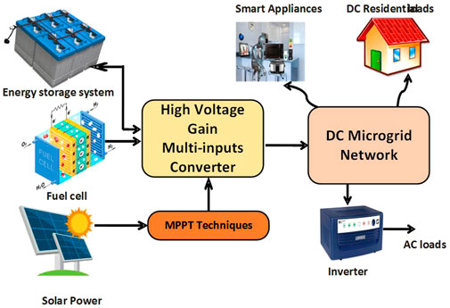
The PV systems’ maximum power point-based operating voltage is extremely low, making them unsuitable for high-voltage applications. The DC-DC converter configuration is utilized to solve the problem by boosting the voltage from a low to high amplitude depending on the load conditions. The voltage gain attributes and procedures of DC-DC step-up converters are thoroughly explored and classified (Zhang et al., 2018), with dual input, dual output, and less converter applications being discussed. In contrast, these converters have a higher magnetic inrush current, lower static voltage gain, and higher ripples in output current. As a result, overall switching and conduction losses in the system have increased. Figure 1 shows a redesigned architecture of the interleaved boost converter block diagram. Furthermore, inductive components are used to interchange energy between sources and loads, which improves DC gain over typical converters. This study proposed the VSS-RBFA-based MPPT algorithm to track the MPP from the PV panel, comparing the results with PSO, modified P&O, ANN, and MPFNN techniques. The performance of the proposed MPPT algorithm along with the converter is analyzed and validated with the CI-based multi-input DC-DC converter topology and with different MPPT techniques. Moreover, the performance analyses have been made with varying temperature and irradiance conditions of the PV system. The converter technique is proposed in Section 2, simulation results and discussion are presented in Section 3, the comparison study is presented in Section 4, experimental results are analyzed in Section 5, and Section 6 presents the conclusion.
2 Proposed converter topology
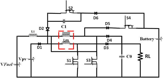
Figure 2 shows the schematic representation for a multi-input interleaved DC-DC converter beyond coupled inductor (CI). It will increase the voltage gain, providing high power density while reducing stress on power semiconductor devices and reducing ripple current. It is specially matched for maximal power applications because it allows for a reduction in input current ripple and conduction mode. VPV and VFC are autonomous sources whose output level is established upon characteristics. L1 and Lm are in arrangement with PV and fuel cell (FC) modules. The RL is equivalent to resistance to the load associated with the DC bus. Switches S1, S2, S3, and S4 are control switches. Diodes are utilized to set up the functions as described. The capacitor C1 is utilized to decrease the stress, and output capacitor C0 is used as an output voltage filter. By extending steps of the interleaved converter, the customized input current reduces the ripple. The inductor is ideally designed with magnetizing, leakage, and two winding of Np and Ns.
The current obtained by the magnetizing inductance is represented as ip and is. Exploiting from a high level of voltage gain, the used converter reaches the designated output level V0 within the cycles. A single CI-based multi-input converter is used as a phase in this approach, and n of these phases are attached in parallel to perform at the same duty ratio but with a (2/n) phase shift in radians. When a system is interleaved, the cell number n is primarily determined by the high voltage ratio and the load’s higher power consumption.
2.1 Modes of operation
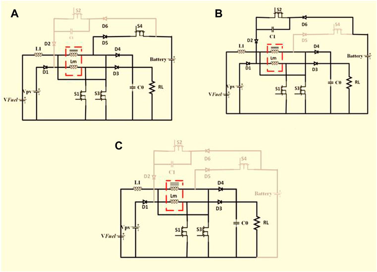
This section discusses the proposed converter operating principles. By regulating the switches, the modern converter can be operated in three different states: 1) PV and FC are both charge batteries and provide power to the load; 2) the FC and PV discharge the battery and supply power to the load; and 3) the load is powered by FC and PV, but the battery is not used.
State-1: PV and FC are charge batteries and provide power to the load.
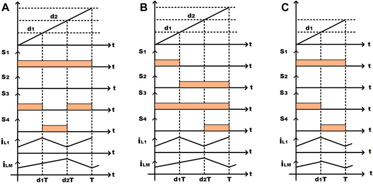
Mode 1: (0 < t < d1T): during this period, S1, S3, D1, D3, and D4 are turned ON. Vfuel and VPV are utilized to charge L1 and LM (see Figure 3A)
Mode 2: (d1T < t < d2T): during this period, S1, S4, D3, and D5 are turned ON. The Vfuel-Vbattery discharged L1 and LM charged by VPV (see Figure 3A)
Mode 3: (d2T < t < T): during this period, S1, S3, D1, D3, and D4 are ON. L1 charged by Vfuel and LM discharged by Vfuel-Vbattery (see Figure 3A)
The magnetization and leakage inductance too are loaded when the device is switched on, resulting in the equation given:
where VLm and VLk are the magnetization inductance voltage and leakage inductance voltage sequentially. A voltage across the magnetization and leakage inductances can be represented as a function of the coupling effect:
where k-coefficient of coupling.
State-2: the FC and PV discharge the battery and supply power to the load.
Mode 1: (0 < t < d1T): during this period S1, S3, D1, D3, and D4 are ON. Vfuel and VPV are utilized to charge L1 and LM (Figure 3B).
Mode 2: (d1T < t < d2T): during this period S2, S3, D2, D3, D4, and D6 are ON. L1 discharged by Vfuel and LM charged by VPV-Vbattery (Figure 3B).
Mode 3: (d2T < t < T): during this period, S2, S3, S4, D2, D3, and D6 are ON. L1 charged by Vfuel and LM discharged by VPV-Vbattery (Figure 3B).
State-3: the load is powered by FC and PV, but the battery is not used.
Mode 1: (0 < t < d1T): during this period S1, S3, D1, D3, and D4 are ON. Vfuel and VPV are utilized to charge L1 and LM (Figure 3C).
Mode 2: (d1T < t < T): during this period, S1, S4, D3, and D5 are ON. Vfuel-Vbattery discharged L1 and LM discharged by VPV (Figure 3C).
The switching sequence for each state and mode is depicted in Figure 4. If the coupled inductor-based multi-input converter is operating in the continuous conduction mode (CCM), when the switches are on and off, the following equations can be obtained using Kirchhoff voltage laws for each mode:
2.2 Steady-state analysis and design details
Using a CI and a managed turn ratio, extremely maximum gain with a minimum duty cycle may be achieved. Voltage spikes across active switches are caused by the associated inductor’s leakage inductance (Tseng et al., 2014; Khalilzadeh and Abbaszadeh, 2015). Several active or passive clamping systems are needed to capture these spikes and restore the leakage energy from the CI to the system (Liu et al., 2016). In large current and power applications, interleaved converters proved to be a good solution. The interleaving technique is utilized to diminish the ripple current.
2.2.1 Voltage gain
The contribution of normal modes and leakage inductance is ignored when calculating the optimum voltage gain. The following equations are determined by requesting the volt-sec balance principle to L1 and LM:
By solving the aforementioned Eq. (9), we get
The CI rms currents may be estimated as
2.2.2 Voltage and current stress on the diode
Voltage beyond the diode is one-fifth time of the voltage stress on the switches. The high stress of voltage beyond the diodes may be communicated as voltage:
The average current stress on the diodes can be determined as follows:
As the diode voltage stress enlarges, the turns ratio enlarges; anyway, this is less than the voltage output.
2.2.3 Voltage stress on the switch
Voltage stress of the switches may be derived as follows:
When the turns ratio is 1, the larger the turns ratio, the lower it actually is. Therefore, metal-oxide semiconductor field-effect transistors (MOSFETs) with a minimum rated voltage and moderate ON-resistance may reduce conduction loss. It is observed that if the turn ratio increases and the voltage gain increases and the voltage of the switch voltage will decrease. The switch’s RMS current could be calculated as follows:
3 Simulation results and discussion
With several DC-DC converters, simulations were run on PSO, modified P&O, ANN, MPFNN, and enhanced VSS-RBFA-based MPPT methods. The performance of an improved VSS-RBFA-based MPPT approach at uniform, non-uniform, and fast variable solar radiation conditions is investigated using the Trina Solar TSM-250pa 05.08 PV array. A PV cell with a single diode circuit is simple to create, but the P-V and I-V properties are erroneous. In order to address this problem, a solar PV cell with a double diode circuit is employed to simulate the PV module in this article.
3.1 Solar PV system with uniform irradiation
Figure 5A shows the change in the duty cycle and output power of an interleaved multi-input DC-DC boost converter with a connected inductor using different MPPT algorithms under uniform irradiation. The modified P&O MPPT topology reduces a converter output power settling time to 0.32 s, which is faster than the PSO technique but has the problem of large conduction losses. Using an improved VSS-RBFA-based MPPT approach, Figure 5A depicts the appropriate duty cycles for the proposed PV-fed converter system to obtain the greatest output power. The multi-input DC-DC converter efficiency using an MPFNN-based MPPT technology is 87.02%, which is lower than the VSS-RBFA-based MPPT topology. As a result of the aforementioned findings, it can be stated that an enhanced proposed technology is appropriate for controlling the duty cycles of a coupled inductor-based converter under uniform irradiation.
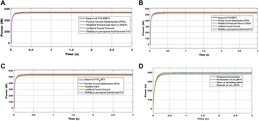
FIGURE 5. (A) At 1,000 W/m2, output power from various MPPT approaches. (B) At 1,000, 900, and 700 W/m2, various MPPT approaches are used to generate output power. (C) At 1,000 and 700 W/m2, respectively, the output power is obtained using various MPPT approaches. (D) VSS-RBFA-based MPPT topology is utilized to calculate the output power of converters under uniform irradiation.
3.2 Solar PV system with PSC
The highest working D and output power of a coupled inductor-based step-up converter using modified P&O MPPT topologies are 399.02 and 399.02 W, respectively, under PSC-1 1000 W/m2, 900 W/m2, and 700 W/m2 (Figure 5B). Its efficiency is 86.62%, which is lower than that of an adaptive PSO-based MPPT approach. By using an enhanced VSS-RBFA-based MPPT approach, the suggested converter increased the PV supply voltage from 110.26 to 199.58 V at 1,000, 900, and 700 W/m2.
3.3 Under fast varying solar radiation
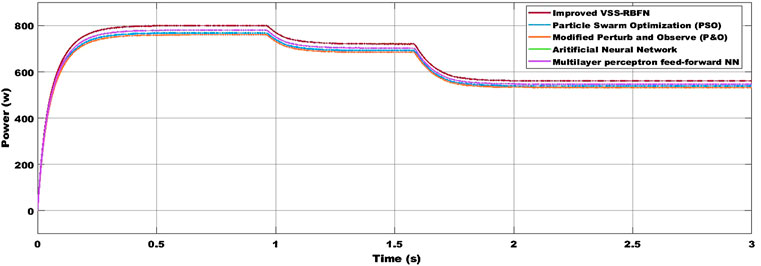
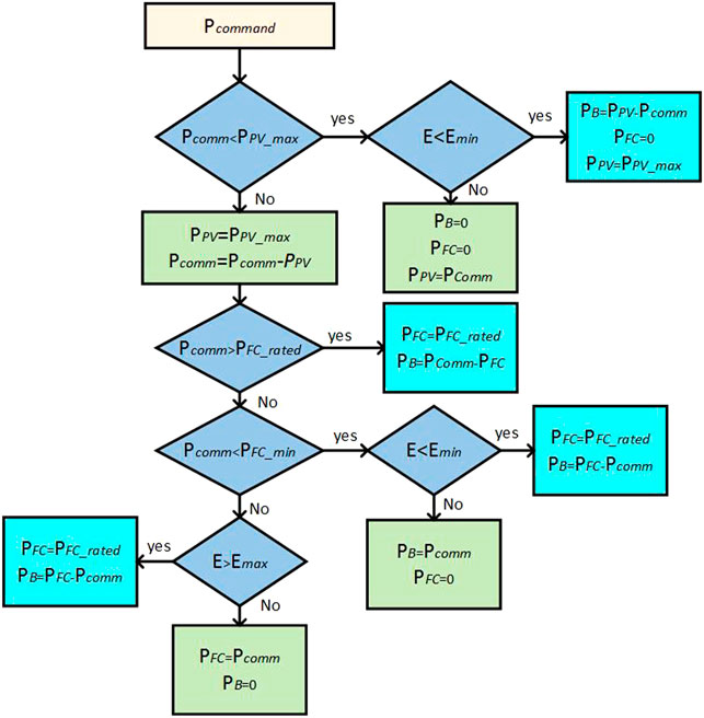
The PV array receives fast-changing radiation as a step signal. Figure 6 shows the reaction of various MPPT algorithms in terms of power production to this rapidly changing radiation. The improved P&O method is found to track the MPP the best from 0 to 3 s of simulation, with tracking effectiveness of 98.8%. In 0.4, 0.42, 0.43, and 0.46 s, the PSO, ANN MPFNN, and enhanced VSS-RBFN track the MPP. The updated P&O tracks the current MPP in 0.41 s with tracing effectiveness of 97.42% when the irradiance unexpectedly changes (at 3 s). PSO and ANN take 0.98 and 0.99 s to follow the MPP, respectively. MPP tracking by upgraded VSS-RBFN has also improved accuracy and speed in this scenario. Using the proposed MPPT approach, the proposed converter output power and efficiency are 400.63 W and 89.23%, respectively. Table 1 shows the performance parameters of the proposed converter while using various MPPT approaches. Compared to the MPFNN, an enhanced VSS-RBFA-based MPPT approach provides rapid network reaction and higher steady power output, as indicated in Table 1. The average duty cycle and output power of the proposed converter using the MPFNN-based MPPT approach are 0.81 and 522.7 W under PSC-2 (1,000, 700, and 600 W/m2) (Figure 5C). The enhanced VSS-RBFA can be seen to track the MPP flawlessly, with no oscillation and a short rising time. When the irradiance and temperature increase or drop in the morning and afternoon, the primary variations may be noted. The PV-module power curves derived with the various MPPT algorithms are almost smooth, except that the P &O curves exhibit slight oscillations when the irradiance becomes almost constant. Compared to the MPFNN, the suggested converter has a lower operating duty cycle thanks to an enhanced VSS-RBFA-based MPPT method. As a result, the switching and conduction of the proposed PV-fed converter system are lowered. In addition, using an enhanced VSS-RBFA-based MPPT approach reduces MPP oscillations and tracking time. Figure 7 shows the flowchart of the proposed circuit under various situations to implement all modes of operation.
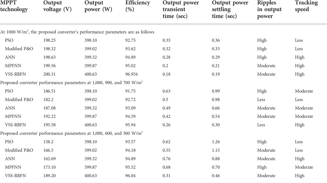
TABLE 1. Based on MATLAB/Simulink results of the proposed converter’s performance while using various MPPT techniques.
4 Comparison study
Based on the evaluation of MPPT techniques presented earlier, an enhanced VSS-RBFA-based MPPT method is suited for solar-fed step-up converter applications. In order to modify the duty cycle for power converter comparisons, an enhanced VSS-RBFA-based MPPT approach is adopted. Figure 5D shows that the output power of the proposed converter using an enhanced VSS-RBFA-based MPPT approach is 400.63 W under uniform irradiation conditions (1,000 W/m2). As a result of the foregoing observations, it can be inferred that the suggested converter outperforms the others. Table 2 summarizes the comparison.
5 Experimental results
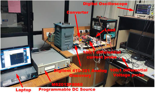
A prototype requirement of the circuit is designed and tested with an M62012P8060 programmable DC power supply to examine the converter performance (see Figure 8). As stated previously, the proposed converter may be used for various domestic and industrial applications, smart buildings, including HEV, and DGs interface. Input sources are mainly PV, FC, and so forth. In order to get experimental results, a DC power supply could be used instead of the current sources, disregarding the power sources’ transient time. As energy storage (ES) component, a lithium-ion (Li-ion) 12-V 7-Ah battery is utilized. Because of its high performance in portable electronic devices, Li-ion batteries are frequently employed (Kumaravel et al., 2019). Li-ion batteries have long cycle life, less self-discharging rate, no memory effects, great reliability, higher temperature performance, great energy density, and are recyclable. However, one of their limitations is their high cost (Kumaravel et al., 2019). Here, the SCT-3080-MOSFET is utilized as a switch. Low on-resistance, high switching frequency, fast switching speed, low power consumption and dissipation, low sensitivity of temperature, and being simple to drive are all benefits of MOSFETs. The hardware prototype’s selected components are used to accomplish the loss analysis. The switch, capacitors, input inductor, diodes, and CI all contribute to the proposed converter’s power losses. Dead time and leakage inductance are neglected to make the analysis simpler.
The input inductor’s copper loss is computed using
The coupled inductor’s copper loss is computed by
where Ipri_rms and Isec_rms are given by Eqs. 11, 12:
Switching loss is ignored once the ZVS turn-on is accomplished. The switches’ conduction loss is computed using
where IS1_rms, IS2_rms, IS3_rms, and IS4_rms are given by Eqs. 17, 18.
The diode’s conduction loss is computed as
The capacitors’ conduction loss is determined as follows:
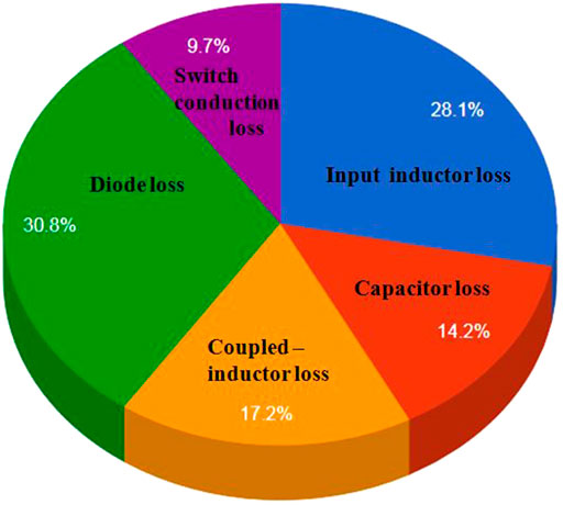
The diodes and inductors are found to be responsible for the majority of the losses. The main switch’s switching loss must be reported if ZVS was not accomplished:
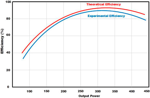
where tRISE is switch voltage rise time, tFALL is switch voltage fall time, I0 is output current, VIN is input voltage, and VOUT is output voltage. If the converter’s switching frequency is high, the switching loss reductions will be even greater. Figure 9 depicts the separation of losses among the elements. According to the same figure, the diodes suffer the most power loss (30.8%). The switches (S1 and S3) have a loss of around 9.7%. Inductors and capacitors have total losses of 28.1% and 14.2%, accordingly. The converter efficiency as a function of output power appears in Figure 10.
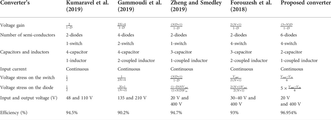
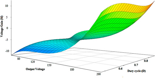
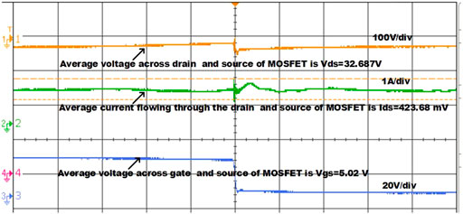
Low on-resistance, high switching frequency, fast switching speed, low power consumption and dissipation, low sensitivity of temperature, and being simple to drive are all benefits of MOSFETs. The voltage gain G improves as the duty cycle rises, as seen in Figure 11. Furthermore, compared to MOSFET, insulated gate bipolar transistors (IGBT) and bipolar junction transistors (BJT) can be utilized for applications of the high switching frequency. To provide the switching pulses for MOSFETs, the DIGILENT-410–321 series type Analog Discovery Wave Generator is employed as a pulse width modulator (PWM). In order to engage the converter circuit, the TLP-250 gate driver circuit is linked between the gate and source terminals of MOSFETs. The switching frequency is 30 kHz, and the D for evaluating the step-up converter is 15%. The gate to source (Vgs) and drain to source (Vds) voltages of MOSFETs are 5.02 and 32.687 V, accordingly. As a result, the switching losses of the converter are diminished. Ferrite cores are used in inductors because of their high switching frequency. Figure 12 highlights the salient features of the proposed converter benchmarked against some similar and modern converters. The inductor L1 is 10.67 mH, and the capacitors are 13.5 μF. Figure 13 shows input and output voltages along with output current, using 20 V for each input voltage that has been adequately raised to around 200 V and the efficiency of the converter is 96.954%. The first mode of operation’s experimental results is as follows: the inductor currents are about 3.2 A. There is an extremely minimal ripple in the system’s output voltage. This is also visible in the waveform of output power, which contains very little ripple. Despite that, the input source’s power/current has a significant amount of ripple, which can be mitigated by having a large capacitor at the input. Anyway, the output voltage is larger than the proposed one with the same duty cycle. Ultimately, consumers demand more energy efficiency, recycling, and proper disposal. In order to accomplish power management, the battery can be charged and discharged. Figure 14 shows the voltage and current across the MOSFET. Inductor and capacitor current and voltages are indicated in Figure 15.
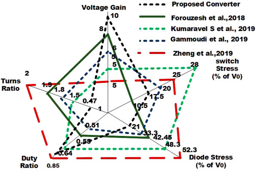
FIGURE 12. Proposed converter’s superior qualities compared to certain current converters are depicted in a radial chart.
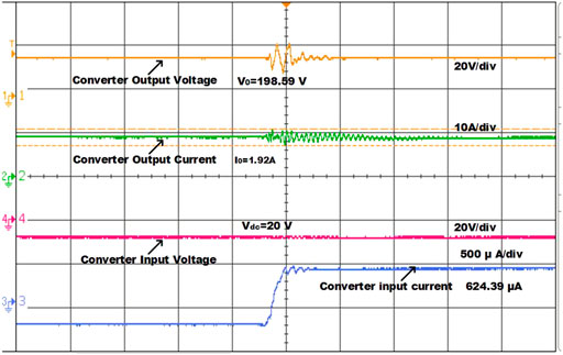
FIGURE 13. Proposed converter’s output voltage, output current, input voltage, and input capacitor current.
6 Conclusion
Using an enhanced VSS-RBFNN, the recommended MPPT technique was successfully developed and used in a coupled inductor-based multi-input DC-DC converter. The proposed technique’s detailed architecture and tracking method were addressed in the model and experiments. The modeling and experimental results demonstrated that the proposed VSS-RBFA-based MPPT technique may trace MPPs rapidly and effectively less than a variety of rapidly changing meteorological circumstances. Compared to other algorithms, the simulation results indicate that the variable step size NN MPPT technique has superior tracing reliability, ripple, response time, and overshoot. The proposed step-up converter has a greater gain, continuous input current, lower stress between the switches, and extensive input and output performance. A 400-W 20-V input 200-V output prototype has been built, and experimental results have been provided to validate the analysis.
Data availability statement
The original contributions presented in the study are included in the article/Supplementary Material. Further inquiries can be directed to the corresponding author.
Author contributions
MB and VI contributed to the conception and design of the study. MB organized the database and performed the statistical analysis. MB wrote the first draft of the manuscript and wrote sections of the manuscript. VI and MB contributed to manuscript revision and read and approved the submitted version.
Conflict of interest
The authors declare that the research was conducted in the absence of any commercial or financial relationships that could be construed as a potential conflict of interest.
The handling editor [RS] is currently organizing a research topic with the author.
Publisher’s note
All claims expressed in this article are solely those of the authors and do not necessarily represent those of their affiliated organizations or those of the publisher, the editors, and the reviewers. Any product that may be evaluated in this article, or claim that may be made by its manufacturer, is not guaranteed or endorsed by the publisher.
References
Alghaythi, M. L., O’Connell, R. M., and Islam, N. E. (2019). “Design of a high step-up dc-dc power converter with voltage multiplier cells and reduced losses on semiconductors for photovoltaic systems,” in 2019 IEEE Electric Ship Technologies Symposium (ESTS), Washington, DC, 14–16 August 2019 (IEEE), 214–218.
Alsumiri, M. (2019). Residual incremental conductance based nonparametric mppt control for solar photovoltaic energy conversion system. Ieee Access 7, 87901–87906. doi:10.1109/access.2019.2925687
Amir, A., Che, H. S., Amir, A., El Khateb, A., and Abd Rahim, N. (2018). Transformerless high gain boost and buck-boost dc-dc converters based on extendable switched capacitor (sc) cell for stand-alone photovoltaic system. Sol. Energy 171, 212–222. doi:10.1016/j.solener.2018.06.078
Babaei, E., Abbasnezhad, A., Sabahi, M., and Hosseini, S. H. (2017). Analysis and design of a softswitching boost dc/dc converter. IET Power Electron. 10 (11), 1353–1362. doi:10.1049/iet-pel.2016.0388
Bairabathina, S., and Balamurugan, S. (2020). Review on non-isolated multi-input step-up converters for grid-independent hybrid electric vehicles. Int. J. hydrogen energy 45 (41), 21687–21713. doi:10.1016/j.ijhydene.2020.05.277
Balasubramanian, I. R., Ilango Ganesan, S., and Chilakapati, N. (2014). Impact of partial shading on the output power of pv systems under partial shading conditions. IET power Electron. 7 (3), 657–666. doi:10.1049/iet-pel.2013.0143
Basha, C. H., and Rani, C. (2020). Different conventional and soft computing mppt techniques for solar pv systems with high step-up boost converters: a comprehensive analysis. Energies 13 (2), 371. doi:10.3390/en13020371
Chandra, S., Gaur, P., and Srishti, (2018). “Maximum power point tracking approaches for wind–solar hybrid renewable energy system—A review,” in Advances in energy and power systems (Singapore: Springer), 3–12. doi:10.20508/ijrer.v7i1.5078.g6969
Chen, Y.-T., Jhang, Y.-C., and Liang, R.-H. (2016). A fuzzy-logic based auto-scaling variable step-size mppt method for pv systems. Sol. Energy 126, 53–63. doi:10.1016/j.solener.2016.01.007
Costanzo, L., Schiavo, A. L., and Vitelli, M. (2019). Design guidelines for the perturb and observe technique for electromagnetic vibration energy harvesters feeding bridge rectifiers. IEEE Trans. Ind. Appl. 55 (5), 5089–5098. doi:10.1109/tia.2019.2923162
Forouzesh, M., Shen, Y., Yari, K., Siwakoti, Y. P., and Blaabjerg, F. (2017). High-efficiency high step-up dc–dc converter with dual coupled inductors for grid-connected photovoltaic systems. IEEE Trans. Power Electron. 33 (7), 5967–5982. doi:10.1109/tpel.2017.2746750
Forouzesh, M., Shen, Y., Yari, K., Siwakoti, Y. P., and Blaabjerg, F. (2018). High-efficiency high step-up DC-DC converter with dual coupled inductors for grid-connected photovoltaic systems. IEEE Trans. Power Electron. 33 (7), 5967–5982.
Gammoudi, R., Brahmi, H., and Hasnaoui, O. (2019). Developed and STM implementation of modified P&O MPPT technique for a PV system over sun. EPE Journal 29 (3), 99–119.
Haroun, R., El Aroudi, A., Cid-Pastor, A., and Mart´ınez-Salamero, L. (2014). “Sliding mode control of output-parallel-connected two-stage boost converters for pv systems,” in 2014 IEEE 11th InternationalMulti-Conference on Systems, Signals & Devices (SSD14), Barcelona, Spain, 11–14 February, 2014 (IEEE), 1–6.
Hosseinzadeh, M., and Salmasi, F. R. (2015). Power management of an isolated hybrid ac/dc micro-grid with fuzzy control of battery banks. IET Renew. Power Gener. 9 (5), 484–493. doi:10.1049/iet-rpg.2014.0271
Hu, X., and Gong, C. (2013). A high voltage gain dc–dc converter integrating coupled-inductor and diode–capacitor techniques. IEEE Trans. Power Electron. 29 (2), 789–800. doi:10.1109/tpel.2013.2257870
Inthamoussou, F. A., De Battista, H., and Mantz, R. J. (2012). New concept in maximum power tracking for the control of a photovoltaic/hydrogen system. Int. J. hydrogen energy 37 (19), 14951–14958. doi:10.1016/j.ijhydene.2012.01.176
Kamarzaman, N. A., and Tan, C. W. (2014). A comprehensive review of maximum power point tracking algorithms for photovoltaic systems. Renew. Sustain. Energy Rev. 37, 585–598. doi:10.1016/j.rser.2014.05.045
Khalilzadeh, M., and Abbaszadeh, K. (2015). Non-isolated high step-up dc–dc converter based on coupled inductor with reduced voltage stress. IET power Electron. 8 (11), 2184–2194. doi:10.1049/iet-pel.2014.0899
Kumar, K., Babu, N. R., and Prabhu, K. (2017). Design and analysis of an integrated cuk-sepic converter with mppt for standalone wind/pv hybrid system. Int. J. Renew. Energy Res. (IJRER) 7 (1), 96–106.
Kumar, N., Singh, B., and Panigrahi, B. K. (2019). Pnklmf-based neural network control and learning-based hc mppt technique for multi objective grid integrated solar pv based distributed generating system. IEEE Trans. Ind. Inf. 15 (6), 3732–3742. doi:10.1109/tii.2019.2901516
Kumaravel, S., Achathuparambil Narayanankutty, R., Rao, V. S., and Sankar, A. (2019). Dual input–dual output dc–dc converter for solar pv/battery/ultra-capacitor powered electric vehicle application. IET Power Electron. 12 (13), 3351–3358. doi:10.1049/iet-pel.2019.0123
Liu, H., Hu, H., Wu, H., Xing, Y., and Batarseh, I. (2016). Overview of high-step-up coupled-inductor boost converters. IEEE J. Emerg. Sel. Top. Power Electron. 4 (2), 689–704. doi:10.1109/jestpe.2016.2532930
Nguyen, M.-K., Duong, T.-D., and Lim, Y.-C. (2017). Switched-capacitor-based dual-switch high-boost dc–dc converter. IEEE Trans. Power Electron. 33 (5), 4181–4189. doi:10.1109/tpel.2017.2719040
Pathak, P. K., and Yadav, A. K. (2019). Design of battery charging circuit through intelligent mppt using spv system. Sol. Energy 178, 79–89. doi:10.1016/j.solener.2018.12.018
Rahimi, T., Ding, L., Gholizadeh, H., Shahrivar, R. S., and Faraji, R. (2021). An ultra high step-up dc–dc converter based on the boost, Luo, and voltage doubler structure: mathematical expression, simulation, and experimental. IEEE Access 9, 132011–132024. doi:10.1109/access.2021.3115259
Ram, J. P., Rajasekar, N., and Miyatake, M. (2017). Design and overview of maximum power pointtracking techniques in wind and solar photovoltaic systems: a review. Renew. Sustain. Energy Rev. 73, 1138–1159. doi:10.1016/j.rser.2017.02.009
Reisi, A. R., Moradi, M. H., and Jamasb, S. (2013). Classification and comparison of maximum power point tracking techniques for photovoltaic system: a review. Renew. Sustain. energy Rev. 19, 433–443. doi:10.1016/j.rser.2012.11.052
Sanghavi, B., Tejaswini, C., and Venkateshappa, V. (2019). Dc/dc boost converter using dsp controller for fuel cell. Perspect. Commun. Embedded-systems Signal-processing-PiCES 2 (10), 248–251.
Saravanan, S., and Babu, N. R. (2016a). Maximum power point tracking algorithms for photovoltaic system–a review. Renew. Sustain. Energy Rev. 57, 192–204. doi:10.1016/j.rser.2015.12.105
Saravanan, S., and Babu, N. R. (2016b). Rbfn based mppt algorithm for pv system with high step up converter. Energy Convers. Manag. 122, 239–251. doi:10.1016/j.enconman.2016.05.076
Sato, Y., Uno, M., and Nagata, H. (2019). Nonisolated multiport converters based on integration of pwm converter and phase-shift-switched capacitor converter. IEEE Trans. Power Electron. 35 (1), 455–470. doi:10.1109/tpel.2019.2912550
Seyedmahmoudian, M., Horan, B., Soon, T. K., Rahmani, R., Oo, A. M. T., Mekhilef, S., et al. (2016). State of the art artificial intelligence-based mppt techniques for mitigating partial shading effects on pv systems–a review. Renew. Sustain. Energy Rev. 64, 435–455. doi:10.1016/j.rser.2016.06.053
Shahir, F. M., Babaei, E., and Farsadi, M. (2018). Extended topology for a boost dc–dc converter. IEEE Trans. Power Electron. 34 (3), 2375–2384. doi:10.1109/tpel.2018.2840683
Sharma, P., and Agarwal, V. (2014). Maximum power extraction from a partially shaded pv array using shunt-series compensation. IEEE J. Photovolt. 4 (4), 1128–1137. doi:10.1109/jphotov.2014.2323698
Singh, B., Bist, V., Chandra, A., and Al-Haddad, K. (2014). Power factor correction in bridgeless-Luo converter-fed bldc motor drive. IEEE Trans. Ind. Appl. 51 (2), 1179–1188. doi:10.1109/tia.2014.2344502
Tiwari, R., and Babu, N. R. (2016). Recent developments of control strategies for wind energy conversion system. Renew. Sustain. Energy Rev. 66, 268–285. doi:10.1016/j.rser.2016.08.005
Tseng, K.-C., Lin, J.-T., and Huang, C.-C. (2014). High step-up converter with three-winding coupled inductor for fuel cell energy source applications. IEEE Trans. Power Electron. 30 (2), 574–581. doi:10.1109/tpel.2014.2309793
Wu, B., Li, S., Liu, Y., and Smedley, K. M. (2015). A new hybrid boosting converter for renewable energy applications. IEEE Trans. Power Electron. 31 (2), 1203–1215. doi:10.1109/tpel.2015.2420994
Yaichi, M., Fellah, M.-K., and Mammeri, A. (2014). A neural network based mppt technique controller for photovoltaic pumping system. Int. J. Power Electron. Drive Syst. 4 (2), 241. doi:10.11591/ijpeds.v4i2.5875
Ye, Y.-m., and Eric Cheng, K. W. (2014). Quadratic boost converter with low buffer capacitor stress. IET Power Electron. 7 (5), 1162–1170. doi:10.1049/iet-pel.2013.0205
Zhang, Y., Gao, Y., Zhou, L., and Sumner, M. (2018). A switched-capacitor bidirectional dc–dc converter with wide voltage gain range for electric vehicles with hybrid energy sources. IEEE Trans. Power Electron. 33 (11), 9459–9469. doi:10.1109/tpel.2017.2788436
Zheng, Y., and Smedley, S. M. (2019). Interleaved high step-up converter integrating coupled inductor and switched capacitor for distributed generation systems. IEEE Trans. Power Electron. 34 (8), 7617–7628.
Nomenclature
ANN artificial neural network
CBC conventional boost converter
CCM continuous conduction mode
CI coupled inductor
DC direct current
ES energy storage
FC fuel cell
FLC fuzzy logic controller
FVSR fast varying solar radiation
GA genetic algorithm
HBC hybrid boost converter
HC Hill climbing
HEV hybrid electric vehicle
IC incremental conductance
IGBT insulated gate bipolar transistor
Li-ion lithium-ion
MBC modified boost converter
MOSFETs metal–oxide semiconductor field-effect transistors
MPFNN multilayer perceptron feedforward neural network
MPP maximum power point
MPPT maximum power point tracking
NN neural network
P&O perturb and observe
PSCs partial shading conditions
PSO particle swarm optimization
PV photovoltaic
QBC quadratic boost converter
RBFN radial basis function network
RE renewable energy
SC switched capacitor
SCBC switched capacitor boost converter
SPV solar photovoltaic
VM voltage multiplier
VSS-RBFA variable step size-radial basis function algorithm
Keywords: coupled inductor, photovoltaic, maximum power point tracking, radial basis function network, high step-up converter
Citation: Bharathidasan M and Indragandhi V (2022) Implementation of radial basis function network-based maximum power point tracking for a PV-fed high step-up converter. Front. Energy Res. 10:915730. doi: 10.3389/fenrg.2022.915730
Received: 08 April 2022; Accepted: 28 June 2022;
Published: 22 August 2022.
Edited by:
Raman Singh, University of the West of Scotland, United KingdomReviewed by:
Tohid Rahimi, Carleton University, CanadaMohamed Salem, Universiti Sains Malaysia (USM), Malaysia
Copyright © 2022 Bharathidasan and Indragandhi. This is an open-access article distributed under the terms of the Creative Commons Attribution License (CC BY). The use, distribution or reproduction in other forums is permitted, provided the original author(s) and the copyright owner(s) are credited and that the original publication in this journal is cited, in accordance with accepted academic practice. No use, distribution or reproduction is permitted which does not comply with these terms.
*Correspondence: Vairavasundaram Indragandhi, aW5kcmFnYW5kaGkudkB2aXQuYWMuaW4=
 Mohan Bharathidasan
 Vairavasundaram Indragandhi