 Huanyu Di
 Yipeng Yan
 Mingxin Zhao
 Mingxin Kang
- 1Automotive Engineering Institute, Guangzhou Automobile Group Co., Ltd, Guangzhou, China
- 2State Key Laboratory of Synthetical Automation for Process Industries, Northeastern University, Shenyang, China
As an important function of the advanced driver assistance system (ADAS), the reversing assistant (RA) achieves trajectory retracing by applying accurate position estimation and tracking control. To overcome the problem of the modeling complexity in dead reckoning for the reversing assistant function, the heading angular rate is compensated by using the extreme learning machine (ELM) to improve the positioning accuracy. In addition, considering the time delay of the steering system, a tracking controller with a feed-forward of the recorded steering angle and a self-tuning PID feedback controller is designed based on the preview-and-following scheme. Vehicle experiments under various reversing scenarios prove that the proposed positioning method and tracking control scheme are effective, the overall lateral error is less than 10 cm, and the heading angle error is less than 1°, which meets the requirements of performance indicators.
1 Introduction
In order to improve driving safety and comfort, a fully autonomous reversing assistant (RA) function is developed and designed by automotive engineers. The merit of the RA function can make the vehicle automatically reverse back to the starting position of the original route with a maximum support of 50 m, and therefore, it is quite helpful for unskilled drivers, especially under some complicated driving scenarios such as narrow roads.
The core techniques of the RA function include vehicle position estimation and trajectory tracking control. Currently, commonly used vehicle positioning technologies include dead reckoning (Skog and Handel, 2009; Alvarez et al., 2012; Wang et al., 2014), inertial navigation (Woodman, 2007; Leppäkoski et al., 2013), satellite positioning (Leppäkoski et al., 2013; Jiménez et al., 2014; Li et al., 2022), visual positioning (Woodman, 2007; Beauregard, 2009), and lidar-based positioning (Shin et al., 2010; Hess et al., 2016). Each method has its own advantages and shortage and can be selected according to the specific application scenario. Among them, dead reckoning is favored because of its advantages such as no external sensor, low cost, fast sampling frequency, and high short-time positioning accuracy. However, its long-distance positioning deviation is large due to the accumulation of systematic and non-systematic errors. To overcome the aforementioned problems, the mainstream approach is to use multi-source and multi-sensor information fusion technology to integrate other positioning information and dead reckoning information, to achieve the overall positioning accuracy (Alvarez et al., 2012; Wang et al., 2014; Zhang et al., 2015; Jian et al., 2020). In addition, there are also attempts to improvepositioning accuracy by compensating and optimizing the angle information in dead reckoning (Tian et al., 2014; Chen et al., 2016; Ho et al., 2016). For tracking control, geometric relation-based control methods (Coulter, 1992; Thrun et al., 2006; Li et al., 2021a; Le et al., 2021), model-based control methods (Guo and Fancher, 1983; Ziegler et al., 2014; Bayuwindra et al., 2016), and preview-and-following theory-based control methods (Guo and Guan, 1993; Falcone et al., 2007; Marino et al., 2011; Shen et al., 2020) are commonly used at present.
Recently, machine learning techniques have attained much attention in many research fields, such as data-driven modeling (Ourmazd, 2020; Cui et al., 2021), prediction (Huang et al., 2006; Liu et al., 2019; Zhou et al., 2021), control (Kang and Gao, 2020; Zhou et al., 2021; Wu et al., 2022), and fault diagnosis (He and Kusiak, 2017; Li et al., 2021b). Machine learning allows a controller to improve its performance by learning from previous events, in the same way humans learn from experiences. Due to the system complexity of the ADAS, the traditional designs based on the mechanism analysis become more difficult, and then the machine learning techniques have been well studied and gradually adopted (Moujahid et al., 2018). As an efficient learning algorithm with lower computational burden, an extreme learning machine (ELM) has gained much attention in ADAS. The ELM is mainly designed for training single hidden layer feed-forward neural networks, and its hidden nodes are randomly initiated, and then determined without time-consuming iteratively tuning (Huang et al., 2006, 2015).
Based on the aforementioned analysis, in view of the requirement of low cost and high precision of RA positioning scheme, a dead reckoning method with a redundant design based on vehicle signals such as wheel speed and front-wheel angle is proposed; at the same time, in order to compensate the accumulated errors caused by the internal and external errors of the system, the ELM is introduced to correct the heading angle and improve the overall positioning accuracy. In terms of tracking control, considering the characteristics of the RA function and engineering needs, the preview-and-following control scheme is used to realize tracking, namely, using the current vehicle position and vehicle motion to calculate the vehicle position at a certain amount of preview time, and the target tracking point of the desired trajectory is determined based on the vehicle position at the preview point, which can deal with time delay greatly; on the basis of the preview, the following controller is designed by using a feed-forward plus self-tuning PID feedback control algorithm. Finally, functional verification is carried out in different scenarios. Experimental results demonstrate that the positioning and control method designed in this study is effective, and the key performance indexes such as lateral error and heading angle error meet the design requirements.
2 Dead Reckoning and Compensation
Dead reckoning calculates the location and the heading of the vehicle’s center of gravity (CG) based on vehicle signals such as four-wheel speeds and steering wheel angle. Also a confidence evaluation method of the CG position was designed to avoid the increase in positioning error due to the slip of individual wheels. At the same time, considering the unpredictable disturbance such as the change of wheel diameter caused by load and the uneven ground, the accurate position estimation model is difficult to be established. Then, an extreme learning machine is adopted to compensate for the model error to improve the positioning accuracy.
2.1 Dead Reckoning Based on Yaw Angle
The schematic diagram of the vehicle coordinates is illustrated in Figure 1. The CG of the vehicle starting time is taken as the origin of coordinates. At low speed, the sideslip angle of the CG is ignored; the yaw rate of the body is calculated according to the Ackerman steering relation and the average yaw rate of the four wheels:
where L and W denote the wheel base and the wheel track, respectively; δ denotes the steering angle of the wheel, R and v are the turning radius and the wheel speed, respectively; ω with and without subscripts are the yaw rate of the specified wheel and the vehicle body, respectively; dt is the sampling time; and the subscripts of the notations such as fl, fr, rl, andrr throughout the article denote the front-left, front-right, rear-left, and rear-right wheels, respectively.
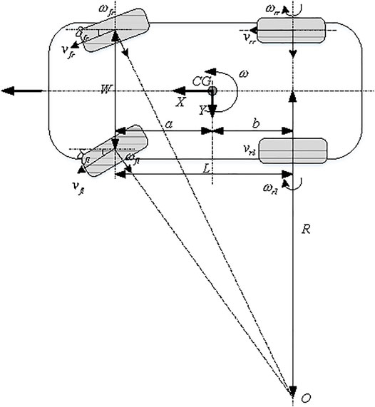
FIGURE 1. Diagram of the vehicle coordinates.
Based on the CG position at the last moment, the initial position of the four wheels was calculated:
where (x, y) denote the coordinate positions and ψ is the yaw angle, the subscript N = 1, 2, 3, and 4 represents the front-left, front-right, rear-right, and rear-left wheel, respectively; and
Furthermore, the four-wheel positions at the current time can be calculated on the basis of no slip assumption, that is,
The four virtual vehicle CG positions (xCG,N, yCG,N) are calculated according to the four-wheel positions with the geometric relationship and the body direction:
where k1 and k2 are defined in Equation 5. Finally, the CG position can be obtained by the following relations:
At the same time, the redundant design is considered to avoid large slips of the individual wheel or large positioning deviations caused by the low tire pressure and the signal disturbance. The evaluation index dC,N is defined as follows:
and take the front-left wheel (i.e., N = 1), for example (same with other wheels), if dC,1 > (dC,2 + dC,3 + dC,4)/3, then this value will be regarded as poor confidence and it will be removed. The final CG position with redundant design will use the following calculation:
2.2 Compensation Scheme Design-Based on ELM
For long-distance dead reckoning, the estimation of the heading angle determines the overall positioning accuracy. In some actual testing scenarios, it is found that due to the mechanical structure of the steering system gap, left and right asymmetry, positioning angle changes, and other factors, the left and right front wheel angle mapping from the steering wheel angle has errors, which leads to inaccurate heading angular rate and indirectly leads to the large cumulative errors in position estimation. Considering the internal parameters of the system affecting the accuracy of heading angular rate cannot be obtained and the compensation model is difficult to be established, an extreme learning machine (ELM) based estimation algorithm is introduced in this study to improve the estimation accuracy of the heading angular rate. The general structure of the ELM can be found in Figure 2.
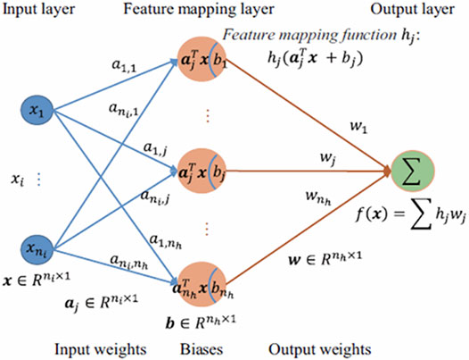
FIGURE 2. General structure of the ELM.
ELM is also referred to as generalized single-hidden layer feed-forward neural networks (FNN) where the hidden layer need not be neuron alike (Huang et al., 2015). Compared to conventional FNN learning methods, ELM adopts Moore–Penrose generalized inverse to set its weights instead of the gradient-based backpropagation strategy. Essentially, the learning process can be implemented without iteratively tuning hidden nodes, and it achieves better generalization performance by minimizing both the training error and the norm of output weights. Therefore, ELM has higher efficiency and generalization ability than other learning methods. Typically, the output function of the ELM is defined as follows:
where
where H denotes the hidden layer output matrix, T is the training goal matrix, and C is regularization coefficient; the solution is as follows:
where I is an identity matrix of nh dimension. Thus, the final ELM-based output for the heading angular rate is
The final vehicle yaw rate estimation is the combination of the calculated yaw rate and the heading angular rate calculation error output by ELM.
2.3 Real Vehicle Validation for Dead Reckoning
In order to verify the effectiveness of the ELM-based compensation strategy, vehicle experiments have been carried out under different conditions including straight line, S-shaped, and right-angle bending. The on-board measurement based on a high-precision global position system (GPS) is used for the baseline benchmark, and the positioning effects with and without ELM compensation have been evaluated, as shown in Figures 3–5.
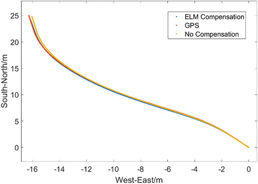
FIGURE 3. Comparison result of the dead reckoning test under straight line conditions.
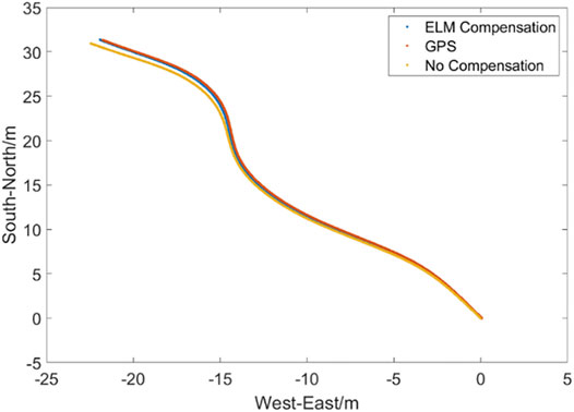
FIGURE 4. Comparison result of the dead reckoning test under S-shaped condition.
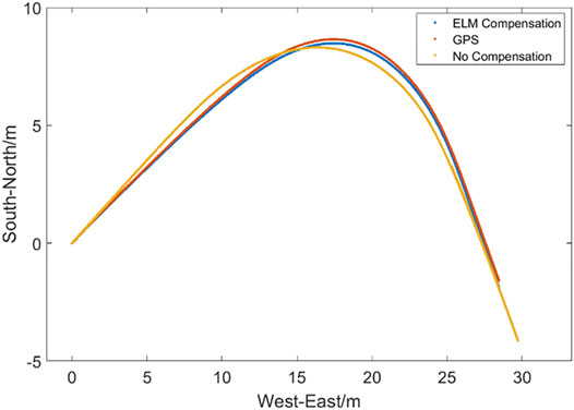
FIGURE 5. Comparison result of the dead reckoning test under right-angle bending condition.
It is obvious from Figures 3–5 that the error accumulation of the dead reckoning is small and the compensation effect is not obvious in the initial short distance. However, as the distance goes far, the dead reckoning without compensation deviates from the GPS measured value, the cumulative error gradually increases, and the positioning accuracy decreases. Even the error becomes more obvious when encountering a large corner. Moreover, the dead reckoning with ELM compensation can always be stable near the measured value with a small error. Although the error increases after a large corner, it can quickly return to the true value after the corner, which improves stability and reliability.
3 Reversing Assistant Controller Design
RA can record the vehicle’s forward track point when the recording condition is satisfied. If the RA function is activated, the system controls the vehicle to follow the recorded track automatically and completes the reverse drive.
3.1 Preview Point Determination
The existence of time delay and external disturbance in the steering system will lead to lag effects in vehicle reversing tracking control, especially when requiring a large turning angle, and therefore leads to the large following error. The preview strategy is used in this study to solve this problem and, based on the vehicle’s current position and state, to calculate its position after a certain previewing time.
As shown in Figure 6, the current position of the vehicle is
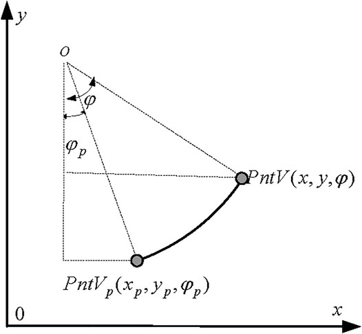
FIGURE 6. Position calculation diagram at preview point.
On the contrary, if
where tp is preview time.
3.2 Target Track Point Selection
The closest tracking point to the vehicle preview point, denoted by PntN, is determined via the recorded forward tracking point sequence and vehicle preview position. According to the relative position relationship between the vehicle preview point and the closest point, the front point PntF and the rear point PntR can be determined, and then the target tracking point PntM is finally obtained. The decision procedure of the target tracking point is illustrated in Figure 7.
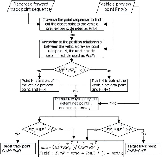
FIGURE 7. Calculation process of the target tracking point.
3.3 Calculation of Lateral and Heading Deviation
Once the target tracking point is determined, the lateral error Δy and heading angle error Δψ of the target tracking point and the vehicle preview point can be calculated. As shown in Figure 8, denote the coordinate of the target point PntM as
where the heading angle error is normalized to [ − π, π].
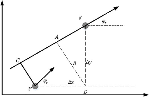
FIGURE 8. Calculation of lateral and heading deviation.
3.4 RA Controller Design
The implementation of the RA function mainly depends on the accuracy of the tracking control by adjusting the steering angle. The recorded steering angle when driving forward, denoted as swe, is used as a reference steering wheel angle at the corresponding position, which provides the feed-forward control input. In addition, considering the external interference and other factors, a parameter adaptive PID feedback control scheme is designed for correction and compensation. The feed-forward and the feedback control variables are given as follows:
where the continuous smooth self-tuning of the proportion parameter is determined by the heading angle error, namely, when the heading angle error is small, the following effect is great, and the proportion coefficient becomes smaller to reduce overshoot and oscillation; on the contrary, when the following effect is poor and the heading angle error becomes larger, the proportion parameter becomes larger accordingly, which improves the response speed and rapidly follows the desired trajectory.
4 Vehicle Test and Validation
The effectiveness of dead reckoning and the RA control method is verified in this section. The real vehicle tests were carried out in some typical conditions including straight line, S-shaped, and right-angle bending, based on an SUV model. The experimental results are shown in Figures 9–13.
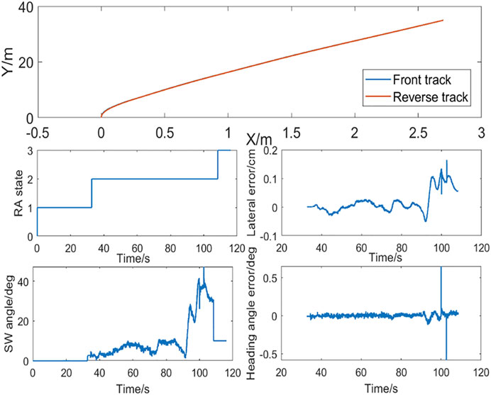
FIGURE 9. RA in straight line condition.
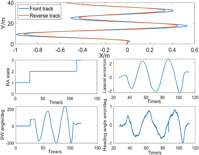
FIGURE 10. RA in S-shaped condition.
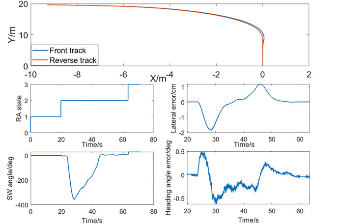
FIGURE 11. RA in right-angle bending condition.
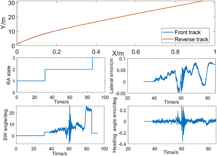
FIGURE 12. RA in a speed bump.
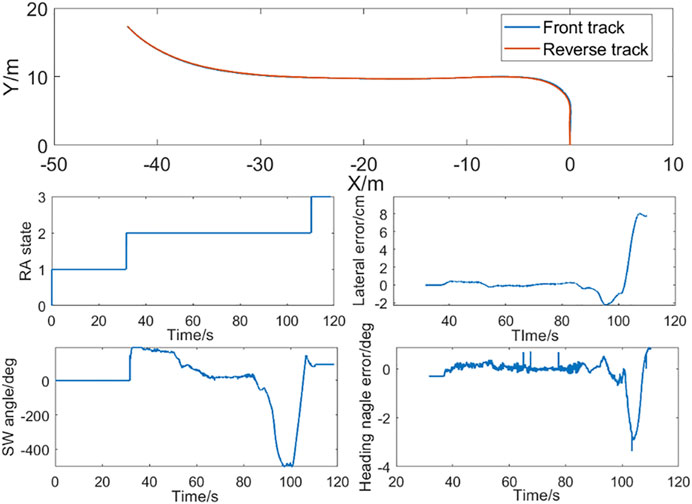
FIGURE 13. RA in a slope.
The straight line RA test result is illustrated in Figure 9. In this straight line test, when the vehicle moves about 38 m and around 36 s, the RA state changes from 1 to 2 and the RA function is activated, and the vehicle starts reversing at a fixed speed of 3 km/h. In the whole process, the wheel angle control quantity is smooth, the forward and reverse tracks coincide, with the lateral error being less than 0.2 cm and the heading angle error being less than 0.2°. Although a few sample periods have a jump, it is due to the temporary jump of each value including the target track point and vehicle preview point, and because of the mechanical filtering effect on the high-frequency signal, there is no sudden change in the intuitive perception.
As shown in Figure 10, in the S-shaped RA scenario, the forward S-shaped trajectory and the reverse trajectory coincide, and the control quantity is smooth without jitter. Although the deviation becomes larger when reversing due to the failure of the optimal preview time, the lateral error is always less than 3 cm, and the heading angle error is less than 1°.
As shown in Figure 11, in the right-angle bending RA scenario, although the error increases at the turning point, the forward trajectory coincides with the reverse trajectory, and the control quantity is smooth without jitter, the lateral error is always less than 2 cm, and the heading angle error is less than 0.5°.
As shown in Figure 12, there is a high degree of convergence between the forward trajectory and the reverse trajectory. In the tracking process, due to the external impact when crossing the speed belt, the steering wheel angle oscillates temporarily after the impact on the steering system due to the driver’s hands off, which leads to the jitter of the point given by the dead reckoning, but it converges quickly. In the process of being hit by the speed bump, the lateral error and heading angle error are kept to a small level.
As shown in Figure 13, after a right-angle bending, the vehicle enters about 8% slope consisting of both longitudinal and lateral slopes. In the whole process, the forward trajectory and reverse trajectory have a high degree of overlap. On the ramp, the lateral error is less than 2 cm, and the heading angle error is less than 1°. The left and right wheel bearing are different due to the existence of the lateral slope, which leads to a small vibration in the steering wheel and a certain degree of the dead reckoning jitter; error has also been accumulated, directly leading to larger error when it enters the flat road and turns right-angle bending, but the lateral error and the heading angle error are always controlled in a small level.
5 Conclusion
In this study, the dead reckoning method with redundant design is proposed, which makes full use of the information of four wheels and eliminates the influence of slip of the wheels on positioning. At the same time, in view of the modeling complexity for position estimation, an ELM is introduced to estimate the heading angular rate and compensate for the dead reckoning. As for tracking control, a feed-forward and feedback PID controller with preview is designed. The proposed positioning and tracking control methods are proved effective, and the design satisfies the requirements of performance indexes via a variety of scenario tests. In addition, considering the mechanical wear and aging with the long-term use of the vehicle system, the ELM-based compensation method may face performance degradation problems; therefore, the future work will focus on the online update of the compensation model to improve the reliability of the RA function.
Data Availability Statement
The raw data supporting the conclusion of this article will be made available by the authors, without undue reservation.
Author Contributions
HD: conceptualization, investigation, experimental data analysis, and original draft writing; YY: extreme learning machine algorithm, experimental data collection, and original draft writing; MZ: tracking controller validation and experimental data analysis; and MK: conceptualization, control algorithm design, and review and editing.
Funding
This work is supported by the Fundamental Research Funds for the Central Universities (Grant No. N2108006).
Conflict of Interest
HD, YY, and MZ were employed by Guangzhou Automobile Group Co., Ltd
The remaining author declares that the research was conducted in the absence of any commercial or financial relationships that could be construed as a potential conflict of interest.
Publisher’s Note
All claims expressed in this article are solely those of the authors and do not necessarily represent those of their affiliated organizations, or those of the publisher, the editors, and the reviewers. Any product that may be evaluated in this article, or claim that may be made by its manufacturer, is not guaranteed or endorsed by the publisher.
References
Alvarez, J. C., Alvarez, D., López, A., and González, R. C. (2012). Pedestrian Navigation Based on a Waist-Worn Inertial Sensor. Sensors 12 (8), 10536–10549. doi:10.3390/s120810536
Bayuwindra, A., Aakre, O. L., Ploeg, J., and Nijmeijer, H. (2016). “Combined Lateral and Longitudinal CACC for a Unicycle Type Platoon [J],” in 2016 IEEE Intelligent Vehicles Symposium (IV), 527–532.
Beauregard, S. (2009). Infrastructureless Pedestrian Positioning [D]. Bremen, Germany: Doktor-ingenieur faculty of mathematics informatics University of Bremen.
Chen, Y.-b., Luo, G.-c., Mei, Y.-s., Yu, J.-q., and Su, X.-l. (2016). UAV Path Planning Using Artificial Potential Field Method Updated by Optimal Control Theory. Int. J. Syst. Sci. 47 (6), 1407–1420. doi:10.1080/00207721.2014.929191
Coulter, R. C. (1992). Implementation of the Pure Pursuit Path Tracking algorithm[R]. Pittsburgh: Carnegie Mellon University Pittsburgh PA Robotics Institute, CMU-RI-TR-92-01.
Cui, S., Pei, X., Jiang, Y., Wang, G., Fan, X., Yang, Q., et al. (2021). Liquefaction within a Bedding Fault: Understanding the Initiation and Movement of the Daguangbao Landslide Triggered by the 2008 Wenchuan Earthquake (Ms = 8.0). Eng. Geol. 295, 106455. doi:10.1016/j.enggeo.2021.106455
Falcone, P., Borrelli, F., Asgari, J., Tseng, H. E., and Hrovat, D. (2007). Predictive Active Steering Control for Autonomous Vehicle Systems. IEEE Trans. Contr. Syst. Technol. 15 (3), 566–580. doi:10.1109/tcst.2007.894653
Guo, K., and Fancher, P. S. (1983). “Preview-follower Method for Modelling Closed-Loop Vehicle Directional Control [J],” in Massachusetts Inst. of Tech., 19th Annual Conference.
Guo, K., and Guan, H. (1993). Modelling of Driver/vehicle Directional Control System [J]. Veh. Syst. Dyn. 22 (1), 141–184. doi:10.1080/00423119308969025
He, Y., and Kusiak, A. (2017). Performance Assessment of Wind Turbines: Data-Derived Quantitative Metrics. IEEE Trans. Sustain. Energy 9 (1), 65–73.
Hess, W., Kohler, D., Rapp, H., and Andor, D. (2016). “Real-time Loop Closure in 2D LIDAR SLAM[C],” in Robotics and Automation (ICRA), 2016 IEEE International Conference on. IEEE (Stockholm, Sweden: IEEE), 1271–1278.
Ho, N.-H., Truong, P., and Jeong, G.-M. (2016). Step-Detection and Adaptive Step-Length Estimation for Pedestrian Dead-Reckoning at Various Walking Speeds Using a Smartphone. Sensors 16 (9), 1423. doi:10.3390/s16091423
Huang, G. B., Zhu, Q. Y., and Siew, C. K. (2006). Extreme Learning Machine: Theory and Applications. Neurocomputing 70 (1), 489–501. doi:10.1016/j.neucom.2005.12.126
Huang, G., Huang, G.-B., Song, S., and You, K. (2015). Trends in Extreme Learning Machines: A Review. Neural Netw. 61, 32–48. doi:10.1016/j.neunet.2014.10.001
Jian, L., Chen, X., Luo, M., and Zhou, Y. (2020). Cooperative Localization for Multiple AUVs Based on the Rough Estimation of the Measurements [J]. Appl. Soft Comput. J. 91, 106197. doi:10.1016/j.asoc.2020.106197
Jiménez, A. R., Zampella, F., and Seco, F. (2014). Improving Inertial Pedestrian Dead Reckoning by Detecting Unmodified Switched-On Lamps in Buildings [J]. Sensors 14, 731–769.
Kang, M.-x., and Gao, J.-w. (2020). Design of an Eco-Gearshift Control Strategy under a Logic System Framework. Front. Inf. Technol. Electron Eng. 21 (2), 340–350. doi:10.1631/fitee.1900459
Le, S., Wu, Y., Guo, Y., and Vecchio, C. D. (2021). Game Theoretic Approach for a Service Function Chain Routing in NFV with Coupled Constraints. IEEE Trans. Circuits Syst. II 68, 3557–3561. Published online. doi:10.1109/TCSII.2021.3070025
Leppäkoski, H., Collin, J., and Takala, J. (2013). Pedestrian Navigation Based on Inertial Sensors, Indoor Map, and WLAN Signals [J]. J. Signals Process. Syst. 71 (3), 287–296.
Li, H., Deng, J., Feng, P., Pu, C., Arachchige, D. D. K., and Cheng, Q. (2021a). Short-Term Nacelle Orientation Forecasting Using Bilinear Transformation and ICEEMDAN Framework. Front. Energy Res. 9, 780928. doi:10.3389/fenrg.2021.780928
Li, H., Deng, J., Yuan, S., Feng, P., and Arachchige, D. D. K. (2021b). Monitoring and Identifying Wind Turbine Generator Bearing Faults Using Deep Belief Network and EWMA Control Charts. Front. Energy Res. 9, 799039. doi:10.3389/fenrg.2021.799039
Li, H., He, Y., Xu, Q., Deng, j., Li, W., and Wei, Y. (2022). Detection and Segmentation of Loess Landslides via Satellite Images: a Two-phase Framework. Landslides 19, 673–686. doi:10.1007/s10346-021-01789-0
Liu, K., Asher, Z., Gong, X., Huang, M., and Kolmanovsky, I. (2019). Vehicle Velocity Prediction and Energy Management Strategy Part 1: Deterministic and Stochastic Vehicle Velocity Prediction Using Machine Learning (No. 2019-01-1051). SAE Tech. Pap.
Marino, R., Scalzi, S., and Netto, M. (2011). Nested PID Steering Control for Lane Keeping in Autonomous Vehicles. Control Eng. Pract. 19 (12), 1459–1467. doi:10.1016/j.conengprac.2011.08.005
Moujahid, A., Tantaoui, M. E., Hina, M. D., Soukane, A., Ortalda, A., ElKhadimi, A., et al. (2018). Machine Learning Techniques in ADAS: A Review, in 2018 International Conference on Advances in Computing and Communication Engineering (ICACCE), 235–242.
Ourmazd, A. (2020). Science in the Age of Machine Learning. Nat. Rev. Phys. 2 (7), 342–343. doi:10.1038/s42254-020-0191-7
Shen, X., Zhang, X., Ouyang, T., Li, Y., and Raksincharoensak, P. (2020). Cooperative Comfortable-Driving at Signalized Intersections for Connected and Automated Vehicles. IEEE Robot. Autom. Lett. 5 (4), 6247–6254. doi:10.1109/LRA.2020.3014010
Shin, S. H., Lee, M. S., Park, C. G., and Hong, H. S. (2010). Pedestrian Dead Reckoning System with Phone Location Awareness Algorithm[C]//Position Location and Navigation Symposium. IEEE Xplore, 97–101.
Skog, I., and Handel, P. (2009). In-Car Positioning and Navigation Technologies-A Survey. IEEE Trans. Intell. Transp. Syst. 10 (1), 4–21. doi:10.1109/tits.2008.2011712
Thrun, S., Montemerlo, M., Dahlkamp, H., Stavens, D., Aron, A., Diebel, J., et al. (2006). Stanley: The Robot that Won the DARPA Grand Challenge. J. Field Robot. 23 (9), 661–692. doi:10.1002/rob.20147
Tian, Z., Zhang, Y., Zhou, M., and Liu, Y. (2014). Pedestrian Dead Reckoning for MARG Navigation Using a Smartphone. EURASIP J. Adv. Signal Process. 2014 (1), 65. doi:10.1186/1687-6180-2014-65
Wang, J., Ni, D., and Li, K. (2014). RFID-based Vehicle Positioning and its Applications in Connected Vehicles. Sensors 14 (3), 4225–4238. doi:10.3390/s140304225
Woodman, O. J. (2007). An Introduction to Inertial Navigation [J]. Cambridge: University of Cambridge, Computer Laboratory. Tech. Rep. UCAMCL-TR-696.
Wu, Y., Zhang, J., and Shen, T. (2022). A Logical Network Approximation to Optimal Control on Continuous Domain and its Application to HEV Control. Sci. CHINA Inf. Sci. doi:10.1007/s11432-021-3446-8
Zhang, H., Yuan, W., Shen, Q., Li, T., and Chang, H. (2015). A Handheld Inertial Pedestrian Navigation System with Accurate Step Modes and Device Poses Recognition. IEEE Sensors J. 15 (3), 1421–1429. doi:10.1109/jsen.2014.2363157
Zhou, J., Wei, J., Yang, T., Zhang, P., Liu, F., and Chen, J. (2021). Seepage Channel Development in the Crown Pillar: Insights from Induced Microseismicity. Int. J. Rock Mech. Min. Sci. 145, 104851. doi:10.1016/j.ijrmms.2021.104851
Keywords: reversing assistant, extreme learning machine, dead reckoning, tracking control, self-tuning PID
Citation: Di H, Yan Y, Zhao M and Kang M (2022) Design and Validation of Reversing Assistant Based on Extreme Learning Machine. Front. Energy Res. 10:914026. doi: 10.3389/fenrg.2022.914026
Received: 06 April 2022; Accepted: 19 April 2022;
Published: 23 May 2022.
Edited by:
Xun ShenXun Shen, Tokyo Institute of Technology, JapanReviewed by:
Fengqiu Liu, Ningbo University of Technology, ChinaZhu Junjun, Yanshan University, China
Copyright © 2022 Di, Yan, Zhao and Kang. This is an open-access article distributed under the terms of the Creative Commons Attribution License (CC BY). The use, distribution or reproduction in other forums is permitted, provided the original author(s) and the copyright owner(s) are credited and that the original publication in this journal is cited, in accordance with accepted academic practice. No use, distribution or reproduction is permitted which does not comply with these terms.
*Correspondence: Mingxin Kang, a2FuZ214QG1haWwubmV1LmVkdS5jbg==