
95% of researchers rate our articles as excellent or good
Learn more about the work of our research integrity team to safeguard the quality of each article we publish.
Find out more
ORIGINAL RESEARCH article
Front. Energy Res. , 01 June 2022
Sec. Smart Grids
Volume 10 - 2022 | https://doi.org/10.3389/fenrg.2022.909044
This article is part of the Research Topic Advanced Intelligent Control Strategies for Solar and Wind Farms View all 6 articles
 Kenneth E. Okedu1,2*
The wind energy conversion technology of a Permanent Magnet Synchronous Generator (PMSG) is very promising in renewable power generation. However, the performance of the grid-connected PMSGs is greatly affected by grid disturbances because their stator windings are interfaced with the grid directly. There are different Fault Current Limiter (FCL) topologies that are capable of improving the Fault Ride Through (FRT) capability of PMSG wind turbines during short circuit faults. This study investigates three types of FCLs connected to the grid side of the PMSG wind turbine: Series Dynamic Braking Resistor (SDBR), traditional Bridge Fault Current Limiter (BFCL), and Capacitive Bridge Fault Current Limiter (CBFCL). Complete modeling of FCLs was derived in order to understand their behaviors accurately during normal conditions and fault periods. The performance of the three FCLs in the PMSG wind turbine was analyzed and compared using a severe three-phase to ground fault at the terminal of the PMSG wind turbine in Power System Computer Design and Electromagnetic Transient Including DC (PSCAD/EMTDC) platform. The same conditions of operation were used in investigating the various FCL strategies in the PMSG wind turbine considered in this study during grid fault for effective comparison.
Wind energy is one of the most promising alternatives to fossil fuels because of its intriguing characteristics like free carbon emissions, enormous availability, low-cost operation, and high-power output (Ali et al., 2022). Wind turbine technology is used to extract the abundant wind energy that turns into mechanical energy, and then electrical energy is produced with the help of a generator. One major shortcoming of wind energy is its unpredictable manner due to the intermittent nature of wind speed (Fogno Fotso et al., 2021). Based on this, there are two major classes of wind turbines: fixed- and variable-speed wind turbines. The technology of the variable-speed wind turbines is mostly employed because of the extensive range of wind speed operations (Sitharthan et al., 2020). The Permanent Magnet Synchronous Generator (PMSG) wind turbine is one of the variable-speed turbines that is used in wind energy conversion due to its higher efficiency and power factor, absence of a gearbox system, no regular maintenance, flexible active and reactive power control, and dissipation, among others (Michalke et al., 2007; Rosyadi et al., 2012), unlike the Doubly Fed Induction Generator (DFIG) wind turbine. However, complex construction and controller control topology are some of the shortcomings of the PMSG wind turbines.
The PMSG wind turbine has a Grid Side Converter (GSC), and Machine Side Converter (MSC) (Abdelrahem et al., 2017; Zhu et al., 2019). Recently, it has been imperative to carry out new studies regarding the Fault Ride Through (FRT) or Low Voltage Ride Through (LVRT) capability of grid-connected wind farms (Prashant et al., 2018; Nian et al., 20192019; Zhu et al., 2019; Firouzi et al., 2020). The stipulated grid codes require wind turbines in wind farms to provide reactive power support to the power grid during steady and transient states (Alepuz et al., 2013); otherwise, the wind farms need to be disconnected from the power grid (Hossain, 2017).
In the literature, there are several FRT or LVRT control strategies regarding PMSG wind turbines, ranging from peak current limitation (Nasiri and Mohammadi, 2017), Maximum Power Point Tracking (MPPT) (Gencer, 2018), expensive active crowbar switch (Yehia et al., 2018), Superconducting Fault Current Limiter (SFCL) (Conroy, 2017), and DC-chopper or braking devices (Nasiri et al., 2015; Yang et al., 2016; Geng et al., 2018). These enhancement schemes of PMSG wind turbines are simple and cost-effective compared to the use of Flexible AC Transmission System (FACTS) devices like Static Synchronous Compensator (STATCOM) (Islam et al., 2020).
Fault Current Limiters (FCLs) are hardware-based solutions in wind turbines and they have proven to be one of the best techniques in fulfilling the FRT or LVRT requirements as set by the grid codes (Okedu et al., 2011). The technology of FCLs is of two categories; SFCL and Non-superconducting Fault Current Limiter (NSFCL). There is no loss of power during nominal operation in SFCLs, and very high-speed control could be achieved, although a complex configuration may be required for maintenance purposes in this type of FRT solution (Firouzi, 2020; Hasan et al., 2021; Islam et al., 2021). However, the NSFCL technology can effectively compensate for the shortcomings of SFCLs and at the same time improve the LVRT capability (Rashid and Ali, 2014; Moghimian et al., 2019). The use of semiconductor devices such as Silicon Controlled Rectifier (SCR) and Insulated Gate Bipolar Transistor (IGBT) gave way for NSFCLs more than the others. Consequently, the control strategies of Series Dynamic Braking Resistors (SDBRs) (Jin Yang et al., 2010; Din et al., 2021), Bridge Fault Current Limiters (BFCLs) with resistive, inductive, and capacitive elements (Firouzi and Gharehpetian, 2013; Rashid and Ali, 2014), series resonance type FCL (Moghimian et al., 2019), and parallel resonance type FCL (PRFCL) (Naderi et al., 2012) show improved performance of variable-speed DFIG-based wind turbines. Among the BFCLs, the capacitive bridge type fault current limiter (CBFCL) is newly introduced to enhance the traditional BFCL and the FRT of wind turbines (Firouzi and Gharehpetian, 2017; Sadi et al., 2020; Padmaja et al., 2021). One of the main reasons for this could be due to the fact that it provides reasonable reactive power that is required to recover the terminal voltage of the wind generators and the entire system during the transient state, compared to the other BFCLs.
This study targets the improved performance of PMSG-based wind generators, considering different control topologies of FCL. The considered FCLs are the SDBR control strategy, the traditional BFCL, and the CBFCL. The mathematical dynamics of the three FCLs in the PMSG wind turbine were presented during the steady and transient states of the wind turbine. The same switching strategy based on the grid voltage during fault conditions was used for all three FCLs for a fair comparison. The robustness of the controllers of the PMSG wind turbine was tested using a severe three-phase to ground fault in the Power System Computer Aided Design and Electromagnetic Transient Including DC (PSCAD/EMTDC) environment.
A PMSG wind turbine is tied to the power grid through its back-to-back full power converters for wind energy conversion. For maximum power tracking, it is controlled by the MSC, and the DC-link voltage regulation for stability purposes is carried out by the GSC (Li et al., 2017; Lee and Chun, 2019; Priyadarshi et al., 2019). The PMSG mechanical power can be expressed as (Heier, 1998)
where
From Equation (2),
where
In Eq. 4,
where
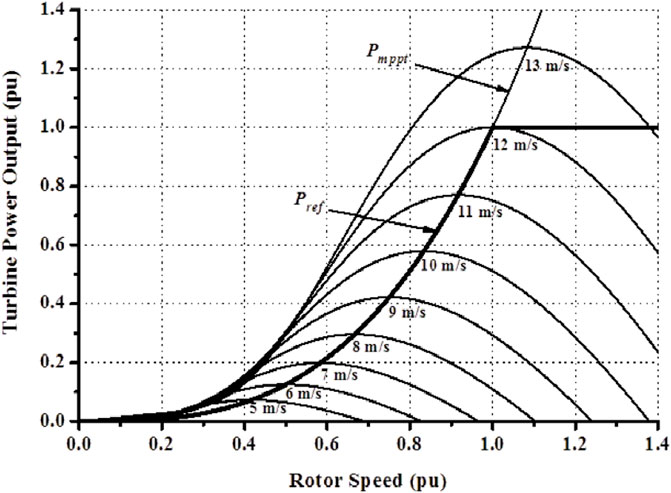
FIGURE 1. Maximum power characteristics of the PMSG wind turbine.
Therefore, the active and reactive powers of the PMSG wind turbine are
while the electrical torque
The model system of this study is shown in Figure 2, where the PMSG wind turbine is connected to an infinite bus, with a system base of 5.0 MVA and a short circuit of 16.67 MVA. The parameters of the model system are given in Table 1 (Okedu and Barghash, 2021; Okedu and Muyeen, 2021). A severe balanced three phase to ground fault occurred on the double circuit of the model system. The three FCLs are connected to the GSC of the PMSG wind turbine as shown in the model system. The connection of FCLs to the PMSG wind turbine would improve its performance during the transient state. The effective parameters of FCLs are given in Table 2. The dynamics of the three FCLs in the PMSG wind turbine are given in the subsequent subsections. The switching of the three FCLs is based on the grid voltage as shown in the model system during a normal state when the grid voltage is above 0.9 pu and during fault conditions when it is less than 0.9 pu.
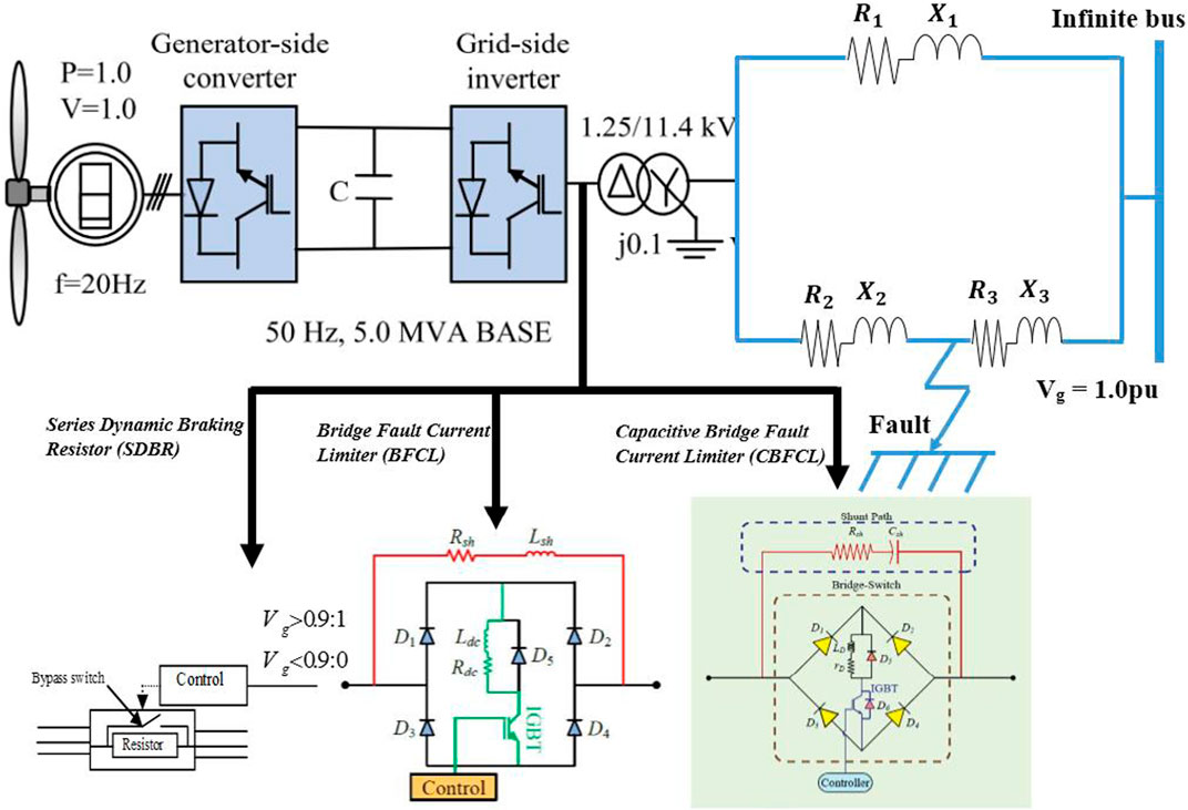
FIGURE 2. PMSG wind turbine with different fault current limiters.
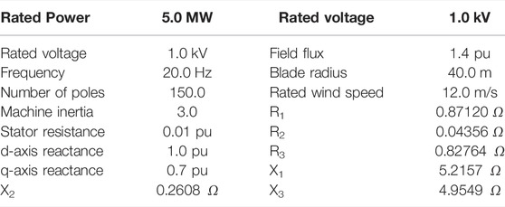
TABLE 1. Parameters of the model system.

TABLE 2. Parameters of the fault current limiters.
The connection of the SDBR in the PMSG-based wind turbine is shown in Figure 3. The SDBR control strategy is based on the current and not voltage (Okedu et al., 2012a; Okedu, 2017). The resistor is bypassed during nominal operation when the switch is conducting, based on the threshold value of the grid voltage. However, during the fault scenario, the switch is off. The switching strategy is based on the grid voltage as explained earlier in Section 3. The SDBR would limit the high rotor inrush current while operating, and thus excessive active power would be achieved (Okedu et al., 2012b; Okedu, 2020). Due to these effects, the MSC and GSC power converters would be effectively balanced, reducing the current in the stator and the DC-link capacitor charging.
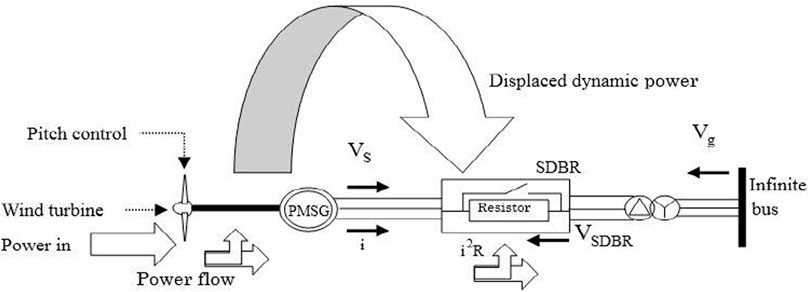
FIGURE 3. Dynamics of SDBR at the stator side of the PMSG wind turbine.
The GSC of the PMSG wind turbine is connected to the R and L parameters of the grid, with AC currents
where
where
For unity power factor,
For unity power factor of the voltage source converter,
For a load
leading to two solutions:
The solution of
But
where
If
Substituting Eq. 36 into (35),
and the voltage source converter operation is possible when
The grid input maximal power
In light of the above analysis, the maximum power transfer of the PMSG GSC during fault would be mitigated, reducing the total current and oscillations by employing the topology of SDBR.
The control structures of a BFCL are shown in Figure 4, and it is basically made up of two distinctive parts. The BFCL main part is a typical bridge circuit with four diodes (D1-D4), while the shunt path made up of the inductor (Lsh) and resistor (Rsh) in series form the other part of the BFCL circuit. An IGBT switch is connected in series with an inductor (Ldc), and (Rdc) acts as an intrinsic resistance of (Ldc) with a very small magnitude that is negligible. In the BFCL, the (Ldc) inductor is a DC reactor due to the fact that the current flows in one direction only through it during the positive and negative half cycle of the alternating current. There is a free-wheeling diode D5 that is connected to the DC reactor to protect the system from inductive kicks during a transient state (Islam et al., 2020). The working principle of the BFCL is such that during a normal or steady state, the current flows through the D1-Ldc-Rdc-IGBT-D4 path for the positive half cycle and through the D3-IGBT-Rdc-Ldc-D2 path for the negative half cycle. It should be noted that the shunt path of the BFCL has a very high impedance, making the bridge switch carry the line current and some negligible leakage currents (Rashid and Ali, 2016; Rashid and Ali, 2017). The control strategy of the BFCL used in this work is based on the threshold grid voltage, which is the same as the SDBR control strategy for a fair comparison. The parameters of the BFCL are as given in Table 2.
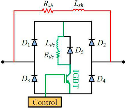
FIGURE 4. Control structure of the BFCL in the PMSG wind turbine.
The CBFCL circuit has four diodes with a switching circuitry of a DC reactor (LD) and (rD) as shown in Figure 5. The shunt path is made up of a capacitor Csh with a series resistor Rsh. In addition, there are two fast recovery diodes (D5 and D6) in the bridge circuit. The parameters of the CBFCL are shown in Table 2, and the switching strategy is the same as those of the SDBR and BFCL for effective comparative study. For practical realization of the operation of the capacitor at a high voltage, the control input which is the duty cycle of a Pulse Width Modulator (PWM) is a function of
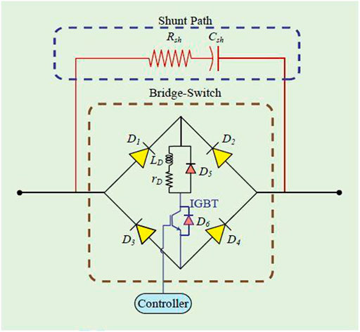
FIGURE 5. Control structure of the CBFCL in the PMSG wind turbine.
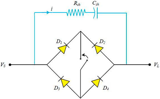
FIGURE 6. On-state equivalent CBFCL in the PMSG wind turbine.
The on-state equation is based on Kirchoff’s voltage law being applied to the terminals of the equivalent circuit of the bridge in Figure 5, as shown in Figure 6. Thus,
Simplification of Eq. 42 leads to
where
The off-state equation is based on Kirchoff’s voltage law being applied to the terminals of the equivalent circuit of the bridge in Figure 5, as shown in Figure 7. Thus,
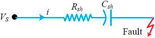
FIGURE 7. Off-state equivalent CBFCL in the PMSG wind turbine.
The current during fault is expressed based on Ohm’s law as
Simplification of Eq. 46 leads to
The control structure of the PMSG wind turbine is shown in Figure 8, where the full power converter is used for isolation of the wind generator from the power network for better protection during grid fault. This is because the grid faults have a huge impact on the direct drive wind energy conversion technology. The MSC regulates the active and reactive power of the PMSG by carrying out abc to dq transformation using the angle position rotor (θr) computed from the rotor speed. The d- and q-axis currents (Isd) and (Isq) control the active power (Ps), and the reactive power (Qs) of the PMSG wind turbine. The reference active power (Pref) is derived from the MPPT of the wind turbine characteristics as discussed earlier, while the reference reactive power (Qs*) is fixed at 0 for the unity power factor. Vsa*, Vsb*, and Vsc* are generated as the reference voltages switching, considering reference voltages Vsd* and Vsq* .
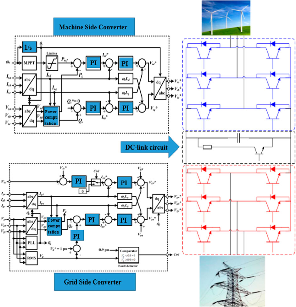
FIGURE 8. Control strategy of the PMSG wind turbine.
The GSC control considers the d-q rotating reference frame, and the voltage of the power grid along with the speed of rotation. The three-phase currents Iga, Igb, and Igc and the three-phase voltages Vga, Vgb, and Vgc are converted to their rotating reference d-q frame. The phase angle (θg) on the GSC is obtained from the Phase Locked Loop (PLL) structure. For effective grid voltage transformation, Vgd is adjusted to a constant and Vgq to zero in the stationary reference frame and the rotating reference d-q frame. The d-axis current (Igd) and the q-axis current (Igq) regulate the active and reactive power that the PMSG is dissipating to the grid. Vgd* and Vgq* are transformed to Vga*, Vgb*, and Vgc* and used for switching purposes. The DC-link voltage (Vdc) is usually kept at unity for an effective active power transfer. The DC-link determines the d-axis current (Igd*) reference signal, while the reactive power determines the q-axis current (Igq*) reference signal. The voltage is proportional to the reactive power, causing the terminal wind turbine voltage to be at 1.0 pu.
The evaluation of the model system of the PMSG wind turbine with the FCLs was done using PSCAD/EMTDC (PSCAD/EMTDC Manual, 2016). A severe three-phase fault of 100 ms occurring at 10.1 s, with the circuit breaker's operation sequence opening and reclosing at 10.2 and 11 s, respectively, was considered in this study. The switching frequency used for the MSC is 1000 Hz, while that of the GSC is 1050 Hz. The solution time step is 10 μS. The evaluation of the system performance was done considering the positions of the SDBR, BFCL, and the CBFCL at the GSC of the PMSG wind turbine. A scenario where no control was implemented in the PMSG wind turbine without considering any of the FCLs was also investigated. The PMSG wind generator was operating at its rated speed during the grid fault. Figure 9A, Figure 10A, Figure 11A, Figure 12A, and Figure 13A show the performances of the various variables of the PMSG wind turbine, and the zoom of these figures are shown in Figure 9B to Figure 13B.
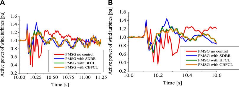
FIGURE 9. (A) Active power of the PMSG wind turbine. (B) Zoom of Figure 9A.
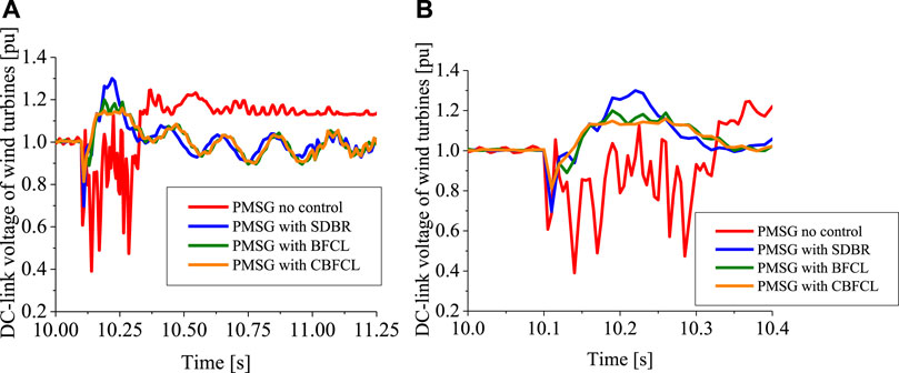
FIGURE 10. (A) DC-link voltage of the PMSG wind turbine. (B) Zoom of Figure 10A.
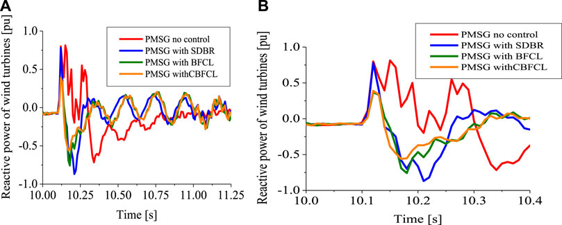
FIGURE 11. (A) Reactive power of the PMSG wind turbine. (B) Zoom of Figure 11A.
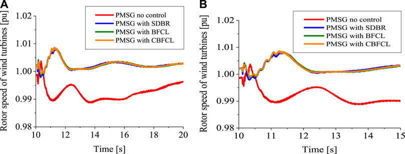
FIGURE 12. (A) Rotor speed of the PMSG wind turbine. (B) Zoom of Figure 12A.
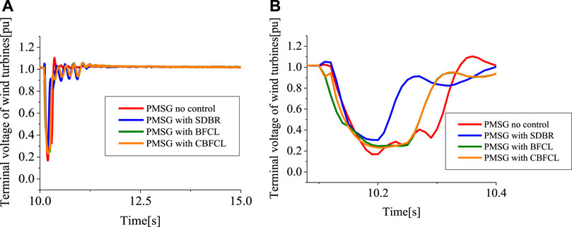
FIGURE 13. (A) Terminal voltage of the PMSG wind turbine. (B) Zoom of Figure 13A.
Figures 9A and 10A show the active power and DC-link voltage of the PMSG wind turbine without FCL control and with SDBR, BFCL, and CBFCL control strategies. From the responses of these figures, inserting SDBR, BFCL, and CBFCL on the GSC of the PMSG wind turbine has a major effect on the active power and DC-link voltage during the transient state. This is because the PMSG wind turbine is decoupled fully from the power grid using a back-to-back power converter. The undershoot, overshoot, and settling time of the active power and DC-link voltage are better in Figures 9A, 10A with the scenarios of FCLs, compared to when no FCL was employed. Connecting the SDBR on the GSC of the PMSG makes the expected high voltage of the wind generator stator circuitry to be divided because of the series connection strategy. However, the performance of the CBFCL is better than those of the SDBR and BFCL because of the additional energy buffer from the capacitive circuit of the CBFCL. Figure 11A shows that the reactive power was better controlled using the CBFCL than the other FCLs and when no FCL was employed. Due to the capacitive circuit of the CBFCL in the PMSG wind turbine during a transient state, the reactive power of the wind turbine would be enhanced.
In Figure 12A, the performance of the rotor speed of the PMSG wind turbine is better with the use of FCLs. The responses of the rotor speed are the same for FCLs in both steady and transient states. This is because the FCL control technique in the PMSG wind turbine has the ability to improve its mechanical output slightly in a steady state and limits its speed during a transient state. Therefore, the performance of the rotor speed in Figure 12A would be with fewer oscillations and a faster settling time. Furthermore, because of the ability of the SDBR to boost the reactive power dissipation as shown in Figure 11A, the terminal voltage of the PMSG wind turbine would be much improved as shown in Figure 13A. The performance of the SDBR FCL is better than the BFCL and CBFCL for the PMSG wind turbine during the transient state. The response of the BFCL and CBFCL are the same for the terminal voltage of the PMSG during transient, though with a faster settling time than the SDBR FCL. Table 3 shows the numerical index performance of the different fault current limiters based on the presented simulation results. In general, the use of FCLs in the PMSG wind turbine would result in no power converter loss in control, with little or no induced overvoltage. The FCL topology would also reduce a high current flow, leading to no dangerous overvoltage and excessive charging current in the power converter’s DC-link capacitor. Although the PMSG wind turbines are more expensive than the DFIG and Squirrel Cage Induction Generator (SCIG) wind turbines, they have better FRT or LVRT performances. By adding additional FCL protection topologies, to the PMSG, the overall cost would not be marginally high due to the fact that FCLs are cheap switching devices. The advancements in power electronic technologies would further drastically reduce the cost of FCLs embedded in the PMSG wind turbines. As part of future work, the proportional integral controllers for PMSG wind turbines would be replaced by the dragon fly optimization algorithm.
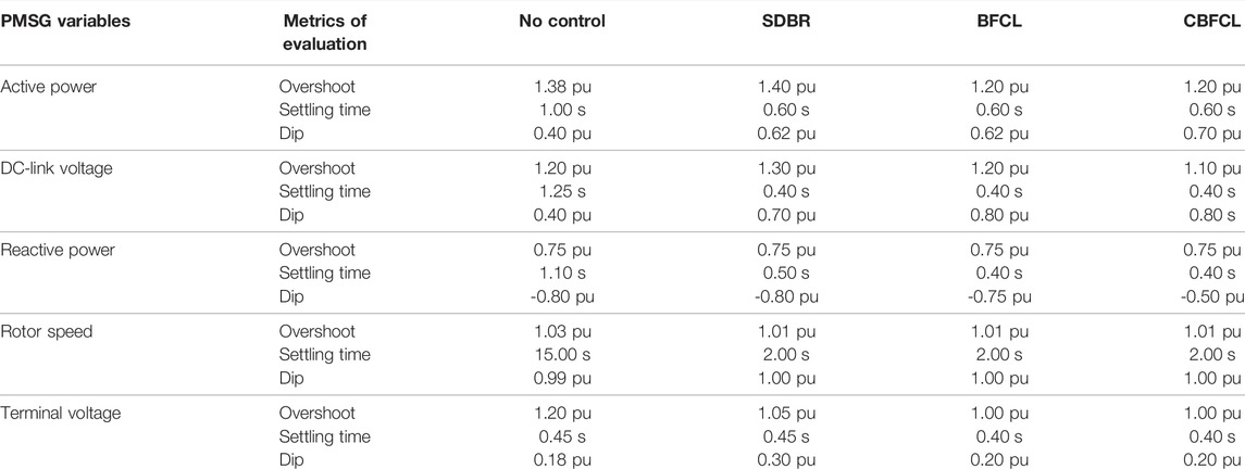
TABLE 3. Numerical index performance of the fault current limiters.
The improved performance of the PMSG wind turbine considering fault current limiters based on series dynamic braking resistor, bridge type fault current limiter, and capacitive bridge type fault current limiter, was investigated in this study. The same threshold value of the power grid voltage during the transient state was used as the switching strategy for the considered FCLs for effective comparison. The responses of FCLs were investigated considering a severe three-phase to ground fault at the terminals of the PMSG. A scenario where no FCL was employed in the PMSG was also investigated. From the obtained results, when no FCL was implemented, the PMSG wind turbine experienced substantial consequences during fault. The use of FCLs improved the performance of the PMSG wind turbine. However, CBFCL performance was superior to those of the SDBR and BFCL under severe fault conditions. The CBFCL provides a smoother and faster response with better overshoot and fast settling time for most of the PMSG variables than the other FCLs. Though the SDBR FCL performed better in the terminal voltage response of the PMSG wind turbine during the fault scenario with regard to faster recovery of the terminal voltage, the settling time was lower than those of the BFCL and CBFCL. Therefore, the CBFCL provides a good example of solving and improving the fault ride-through or low voltage ride-through capability of PMSG wind farms.
The original contributions presented in the study are included in the article/supplementary material; further inquiries can be directed to the corresponding author.
KO carried out all contributions.
The author declares that the research was conducted in the absence of any commercial or financial relationships that could be construed as a potential conflict of interest.
All claims expressed in this article are solely those of the authors and do not necessarily represent those of their affiliated organizations, or those of the publisher, the editors, and the reviewers. Any product that may be evaluated in this article, or claim that may be made by its manufacturer, is not guaranteed or endorsed by the publisher.
Abdelrahem, M., Hackl, C. M., and Kennel, R. (2017). Simplified Model Predictive Current Control without Mechanical Sensors for Variable-Speed Wind Energy Conversion Systems. Electr. Eng. 99, 367–377. doi:10.1007/s00202-016-0433-y
Alepuz, S., Calle, A., Busquets-Monge, S., Kouro, S., and Wu, B. (2013). Use of Stored Energy in PMSG Rotor Inertia for Low-Voltage Ride-Through in Back-To-Back NPC Converter-Based Wind Power Systems. IEEE Trans. Ind. Electron. 60, 1787–1796. doi:10.1109/tie.2012.2190954
Ali, A., Mahmoud, K., and Lehtonen, M. (2022). Optimal Planning of Inverter‐based Renewable Energy Sources towards Autonomous Microgrids Accommodating Electric Vehicle Charging Stations. IET Generation Trans & Dist 16 (2), 219–232. doi:10.1049/gtd2.12268
Conroy, J. F. W. (2017). Low-voltage Ride-Through of a Full Converter Wind Turbine with Permanent Magnet Generator. IET Renew. Power Gener. 1, 182–189.
Din, Z., Zhang, J., Xu, Z., Zhang, Y., and Zhao, J. (2021). Low Voltage and High Voltage Ride‐through Technologies for Doubly Fed Induction Generator System: Comprehensive Review and Future Trends. IET Renew. Power Gen. 15 (3), 614–630. doi:10.1049/rpg2.12047
Firouzi, M., and Gharehpetian, G. B. (2013). Improving Fault Ride-Through Capability of Fixed-Speed Wind Turbine by Using Bridge-type Fault Current Limiter. IEEE Trans. Energy Convers. 28 (2), 361–369. doi:10.1109/tec.2013.2248366
Firouzi, M., and Gharehpetian, G. B. (2017). Lvrt Performance Enhancement of Dfig-Based Wind Farm by Capacitive Bridge-type Fault Current Limiter. IEEE Trans. Sustain. Energy 9 (3), 1118–1125.
Firouzi, M. (2020). Low-voltage Ride-Through (Lvrt) Capability Enhancement of Dfig-Based Wind Farm by Using Bridge-type Superconducting Fault Current Limiter (Btsfcl). J. Power Technol. 99 (4), 245–253.
Firouzi, M., Nasiri, M., Benbouzid, M., and Gharehpetian, G. B. (2020). Application of Multi‐step Bridge‐type Fault Current Limiter for Fault Ride‐through Capability Enhancement of Permanent Magnet Synchronous Generator‐based Wind Turbines. Int. Trans. Electr. Energy Syst. 30 (11), 1–10. doi:10.1002/2050-7038.12611
Fogno Fotso, H. R., Aloyem Kaze, C. V., and Djuidje Kenmoe, G. (2021). A Novel Hybrid Model Based on Weather Variables Relationships Improving Applied for Wind Speed Forecasting. Int. J. Energy Environ. Eng. 13, 1–14. doi:10.1007/s40095-021-00408-x
Gencer, A. (2018). Analysis and Control of Fault Ride through Capability Improvement PMSG Based on WECS Using Active Crowbar System during Different Fault Conditions. Elektron. Elektrotech. 24, 64–69. doi:10.5755/j01.eie.24.2.20637
Geng, H., Liu, L., and Li, R. (2018). Synchronization and Reactive Current Support of PMSG-Based Wind Farm during Severe Grid Fault. IEEE Trans. Sustain. Energy 9, 1596–1604. doi:10.1109/tste.2018.2799197
Hasan, J., Islam, M. R., Islam, M. R., Kouzani, A. Z., and Mahmud, M. A. P. (2021). A Capacitive Bridge-type Superconducting Fault Current Limiter to Improve the Transient Performance of Dfig/pv/sg-Based Hybrid Power System. IEEE Trans. Appl. Supercond. 31, 1–5. doi:10.1109/TASC.2021.3094422
Heier, S. (1998). “Wind Energy Conversion Systems,” in Grid Integration of Wind Energy Conversion Systems (Chicester, UK: John Wiley & Sons), 34–36.
Hossain, M. E. (2017). A Non-linear Controller Based New Bridge Type Fault Current Limiter for Transient Stability Enhancement of DFIG Based Wind Farm. Electr. Power Syst. Res. 152, 466–484. doi:10.1016/j.epsr.2017.07.033
Islam, M. R., Hasan, J., Hasan, M. M., Huda, M. N., Hossain Sadi, M. A., and AbuHussein, A. (2021). Performance Improvement of DFIG‐based Wind Farms Using NARMA‐L2 Controlled Bridge‐type Flux Coupling Non‐superconducting Fault Current Limiter. IET Gener. Transm. Distrib. 14 (26), 6580–6593. doi:10.1049/iet-gtd.2019.1917
Islam, M. R., Huda, M. N., Hasan, J., Sadi, M. A. H., AbuHussein, A., Roy, T. K., et al. (2020). Fault Ride through Capability Improvement of Dfig Based Wind Farm Using Nonlinear Controller Based Bridge-type Flux Coupling Non-superconducting Fault Current Limiter. Energies 13 (7), 1696. doi:10.3390/en13071696
Jin Yang, J., Fletcher, J. E., and O'Reilly, J. (2010). A Series-Dynamic-Resistor-Based Converter Protection Scheme for Doubly-Fed Induction Generator during Various Fault Conditions. IEEE Trans. Energy Convers. 25 (2), 422–432. doi:10.1109/tec.2009.2037970
Lee, S.-W., and Chun, K.-H. (2019). Adaptive Sliding Mode Control for PMSG Wind Turbine Systems. Energies 12, 595. doi:10.3390/en12040595
Li, S., Haskew, T. A., and Xu, L. (2010). Conventional and Novel Control Designs for Direct Driven PMSG Wind Turbines. Electr. Power Syst. Res. 80, 328–338. doi:10.1016/j.epsr.2009.09.016
Li, Y., Xu, Z., and Wong, K. P. (2017). Advanced Control Strategies of PMSG-Based Wind Turbines for System Inertia Support. IEEE Trans. Power Syst. 32, 3027–3037. doi:10.1109/tpwrs.2016.2616171
MATLAB, (2022). MATLAB Documentation Center. Available online: http://www.mathworks.co.jp/jp/help/(accessed on March 12, 2012).
Michalke, G., Hansen, A. D., and Hartkopf, T. (2007). “Control Strategy of a Variable Speed Wind Turbine with Multi-Pole Permanent Magnet Synchronous Generator,” in Proceedings of European Wind Energy Conference and Exhibition, Milan, Italy, 7–10 May 2007.
Moghimian, M. M., Radmehr, M., and Firouzi, M. (2019). Series Resonance Fault Current Limiter (Srfcl) with Mov for Lvrt Enhancement in Dfig-Based Wind Farms. Electr. Power Components Syst. 47 (19-20), 1814–1825. doi:10.1080/15325008.2020.1731873
Muyeen, S. M., Al-Durra, A., and Tamura, J. (2011). Variable Speed Wind Turbine Generator System with Current Controlled Voltage Source Inverter. Energy Convers. Manag. 52 (7), 2688–2694. doi:10.1016/j.enconman.2011.02.001
Naderi, S. B., Jafari, M., and Hagh, M. T. (2012). Parallel-resonance-type Fault Current Limiter. IEEE Trans. Industrial Electron. 60 (7), 2538–2546.
Nasiri, M., Milimonfared, J., and Fathi, S. H. (2015). A Review of Low-Voltage Ride-Through Enhancement Methods for Permanent Magnet Synchronous Generator Based Wind Turbines. Renew. Sustain. Energy Rev. 47, 399–415. doi:10.1016/j.rser.2015.03.079
Nasiri, M., and Mohammadi, R. (2017). Peak Current Limitation for Grid Side Inverter by Limited Active Power in PMSG-Based Wind Turbines during Different Grid Faults. IEEE Trans. Sustain. Energy 8, 3–12. doi:10.1109/tste.2016.2578042
Nian, H., Xu, Y., Chen, L., and Li, G. (20192019). Frequency Coupling Characteristic Modeling of Grid-Connected Inverter and System Stability Analysis. Proc. CSEE 39, 1421–1431.
Okedu, K. E., and Barghash, H. (2021). Enhancing the Transient State Performance of Permanent Magnet Synchronous Generator Based Variable Speed Wind Turbines Using Power Converters Excitation Parameters. Front. Energy Res. 9, 109–120. doi:10.3389/fenrg.2021.655051
Okedu, K. E. (2020). Determination of the Most Effective Switching Signal and Position of Braking Resistor in DFIG Wind Turbine under Transient Conditions. Electr. Eng. 102 (11), 471–480. doi:10.1007/s00202-019-00888-5
Okedu, K. E. (2017). Effect of ECS Low‐pass Filter Timing on Grid Frequency Dynamics of a Power Network Considering Wind Energy Penetration. IET Renew. Power Gener. 11 (9), 1194–1199. doi:10.1049/iet-rpg.2016.0855
Okedu, K. E., and Muyeen, S. M. (2021). Enhanced Performance of PMSG Wind Turbines during Grid Disturbance at Different Network Strengths Considering Fault Current Limiter. Int. Trans. Electr. Energ Syst. 31 (8), 1–21. doi:10.1002/2050-7038.12985
Okedu, K. E., Muyeen, S. M., Takahashi, R., and Tamura, J. (2011). “Improvement of Fault Ride through Capability of Wind Farm Using DFIG Considering SDBR,” in 14th European Conference of Power Electronics EPE, Birmingham, United Kingdom, August 2011, 1–10.
Okedu, K. E., Muyeen, S. M., Takahashi, R., and Tamura, J. (2012). Wind Farm Stabilization by Using DFIG with Current Controlled Voltage Source Converters Taking Grid Codes into Consideration. IEEJ Trans. PE 132 (3), 251–259. doi:10.1541/ieejpes.132.251
Okedu, K. E., Muyeen, S. M., Takahashi, R., and Tamura, J. (2012). Wind Farms Fault Ride through Using DFIG with New Protection Scheme. IEEE Trans. Sustain. Energy 3 (2), 242–254.
Padmaja, A., Shanmukh, A., Mendu, S. S., Devarapalli, R., Serrano González, J., and García Márquez, F. P. (2021). Design of Capacitive Bridge Fault Current Limiter for Low-Voltage Ride-Through Capacity Enrichment of Doubly Fed Induction Generator-Based Wind Farm. Sustainability 13 (12), 6656. doi:10.3390/su13126656
Prashant, M. T., Subhendu, S. S., and Chatterjee, K. (2018). Enhancement of Low‐voltage Ride through of Wind Energy Conversion System Using Superconducting Saturated Core Fault Current Limiter. Int. Trans. Electr. Energy Syst. 29 (4), 1–8.
Priyadarshi, N., Ramachandaramurthy, V., Padmanaban, S., and Azam, F. (2019). An Ant Colony Optimized MPPT for Standalone Hybrid PV-Wind Power System with Single Cuk Converter. Energies 12, 167. doi:10.3390/en12010167
Rashid, G., and Ali, M. H. (2014). A Modified Bridge-type Fault Current Limiter for Fault Ride-Through Capacity Enhancement of Fixed Speed Wind Generator. IEEE Trans. Energy Convers. 29 (2), 527–534.
Rashid, G., and Ali, M. H. (2017). Fault Ride through Capability Improvement of DFIG Based Wind Farm by Fuzzy Logic Controlled Parallel Resonance Fault Current Limiter. Electr. Power Syst. Res. 146, 1–8. doi:10.1016/j.epsr.2017.01.018
Rashid, G., and Ali, M. H. (2016). Nonlinear Control-Based Modified BFCL for LVRT Capacity Enhancement of DFIG-Based Wind Farm. IEEE Trans. Energy Convers. 32, 284–295.
Rosyadi, M., Muyeen, S. M., Takahashi, R., and Tamura, J. (2012). A Design Fuzzy Logic Controller for a Permanent Magnet Wind Generator to Enhance the Dynamic Stability of Wind Farms. Appl. Sci. 2, 780–800. doi:10.3390/app2040780
Sadi, M. A. H., AbuHussein, A., and Shoeb, M. A. (2020). Transient Performance Improvement of Power Systems Using Fuzzy Logic Controlled Capacitive-Bridge Type Fault Current Limiter. IEEE Trans. Power Syst. 36 (1), 323–335.
Sitharthan, R., Karthikeyan, M., Sundar, D. S., and Rajasekaran, S. (2020). Adaptive Hybrid Intelligent Mppt Controller to Approximate Effectual Wind Speed and Optimal Rotor Speed of Variable Speed Wind Turbine. ISA Trans. 96, 479–489. doi:10.1016/j.isatra.2019.05.029
Yang, S., Zhou, T., Sun, D., Xie, Z., and Zhang, X. (2016). A SCR Crowbar Commutated with Power Converter for DFIG-Based Wind Turbines. Int. J. Electr. Power & Energy Syst. 81, 87–103. doi:10.1016/j.ijepes.2016.01.039
Yehia, D. M., Mansour, D.-E. A., and Yuan, W. (2018). Fault Ride-Through Enhancement of PMSG Wind Turbines with DC Microgrids Using Resistive-type SFCL. IEEE Trans. Appl. Supercond. 28, 1–5. doi:10.1109/tasc.2018.2821362
Keywords: grid fault, PMSG wind turbine, wind energy, stability analysis, renewable energy
Citation: Okedu KE (2022) Improving the Performance of PMSG Wind Turbines During Grid Fault Considering Different Strategies of Fault Current Limiters. Front. Energy Res. 10:909044. doi: 10.3389/fenrg.2022.909044
Received: 31 March 2022; Accepted: 27 April 2022;
Published: 01 June 2022.
Edited by:
Liping Guo, Northern Illinois University, United StatesCopyright © 2022 Okedu. This is an open-access article distributed under the terms of the Creative Commons Attribution License (CC BY). The use, distribution or reproduction in other forums is permitted, provided the original author(s) and the copyright owner(s) are credited and that the original publication in this journal is cited, in accordance with accepted academic practice. No use, distribution or reproduction is permitted which does not comply with these terms.
*Correspondence: Kenneth E. Okedu, T2tlZHVrZW5uZXRoQG51LmVkdS5vbQ==
Disclaimer: All claims expressed in this article are solely those of the authors and do not necessarily represent those of their affiliated organizations, or those of the publisher, the editors and the reviewers. Any product that may be evaluated in this article or claim that may be made by its manufacturer is not guaranteed or endorsed by the publisher.
Research integrity at Frontiers
Learn more about the work of our research integrity team to safeguard the quality of each article we publish.