 Chu Tianfeng1,2*
 Zhao Pengwei
 Ling Zhaowei
94% of researchers rate our articles as excellent or good
Learn more about the work of our research integrity team to safeguard the quality of each article we publish.
Find out more
ORIGINAL RESEARCH article
Front. Energy Res., 27 May 2022
Sec. Smart Grids
Volume 10 - 2022 | https://doi.org/10.3389/fenrg.2022.907787
This article is part of the Research TopicControl, Operation and Trading Strategies of Intermittent Renewable Energy in Smart GridsView all 46 articles
Aiming at the grid connection stability of renewable energy generation Voltage Source Converters (VSCs), an active support integrated control strategy is proposed in this article. First, the standard third-order model based on synchronous generator is established, and the renewable energy generation VSCs are equivalent to an approximate synchronous voltage source with the excitation system and speed regulation system. Second, an improved virtual impedance control is added on the basis of the model, which can reduce the impact of impulse current and improve the reactive power support capacity during fault by switching the virtual impedance during fault. At the same time, a virtual dual PSS control is added to the model, and the damping torque method is used to provide positive damping torque for the system and improve the oscillation suppression ability of the system. Finally, a simulation system is built to verify the correctness and effectiveness of the proposed control strategy.
With the continuous development of renewable energy, a new type of power system with new energy is gradually replacing the power system with traditional generators as the main body. Among them, the high proportion of renewable energy and the high proportion of power electronic equipment are typical features of the new power system. Since the new energy units rely mainly on the power electronics converter VSC to connect to the network, this will replace the traditional units which rely on the rotating large axis to provide inertia support. As a result, the overall rigid inertia of the system decreases, which brings new problems to the safe and stable operation of the power system (Kehe et al., 2019; Zhenning et al., 2019). As a result, the active support control technology emerged as the times require, which is equivalent to the traditional synchronous generator mathematically and physically, and can provide certain frequency and voltage support to the power network (Zhipeng et al., 2014; Tianwen et al., 2015; Chong et al., 2015; Fu et al., 2020).
In order to improve the VSC frequency modulation capability of the new energy units, the concept and application of virtual synchronous generator (VSG) are studied by Frack et al. (2015) and Driesen and Visscher (2008). A third-order VSG model is also presentedby Loix et al. (2009). It improves the frequency modulation characteristics of the virtual synchronous generator by adding first-order filter links to the virtual damp branch and the frequency feedback branch, respectively. A mechanism for VSG voltage, frequency, active, and reactive power control is introduced (Fu et al., 2015; Xiangwu and Desheng, 2018). A microgrid virtual synchronous generator with PQ and VF control functions is designed. Its synchronous inductance, damping factor, inertia, and other parameters can be flexibly designed without manufacturing restrictions to meet the different operation requirements of the microgrid (Yang et al., 2011). One way to stabilize the frequency of synchronous generators is to add virtual inertia to the distributed generator. This principle has been studied by many authors. In the case of wind power, only the energy stored in distributed resources is used, which is the inertia of wind turbines (Ekanayake, 2003; Ekanayake and Jenkins, 2004; Lalor et al., 2004; Li et al., 2021a). On the other hand, the advantage of VSG control is that its swing equation parameters can be used in real time, so that it can get faster and more stable operation. Using this feature of VSG system, a VSG system with adaptive virtual inertia is introduced. The scheme eliminates the oscillation, thereby increasing the reliability of the VSG unit to change or perturbate Alipoor et al., (2013) analyzed the influence of different control on the frequency of power network and distinguished the characteristics of inertia support and primary frequency modulation support (Xiaohui et al., 2018). A new VSG power frequency control model is presented, which improves power allocation and suppresses oscillations by discriminating between improved frequency modulation and damping coefficients (Xiangwu and Jiaoxin, 2019).
In view of the voltage stability in the case of new energy unit failure, Shengwen et al. (2011) and Li et al. (2021b) uses the double closed-loop control strategy to adjust the output power of the wind turbine side converter by relying on the detection of current and generator speed, so as to make the fan operate stably during the failure. Ge et al. (2011) presents an improved instantaneous power component method, in which the positive and negative sequence components are decomposed, so that the fan does not go offline under asymmetric faults (Lu et al., 2018). A fault current limiter (VI-FCL) based on virtual impedance is proposed, which can effectively suppress the fault current and oscillation during recovery by improving the inverter droop control to attach a virtual impedance control loop.
On the analysis of damping characteristics of renewable energy unit VSCs, (Yilin et al., 2021) a design method of virtual power system stabilizer is presented, which can compensate virtual excitation equivalent moment (Ruomei et al., 2019). The idea of Power System Stabilizer (PSS) to compensate negative damping moment and the design method of phase compensation are analyzed by using the method of damping moment to maximize the compensated damping moment. The principle of phase compensation for fast excitation system with (PSS-AVR) parallel model is discussed. The general idea of the damping moment analysis is deduced through the elimination change of matrix, and the influence of different parameters in virtual synchronizer on the system damping moment coefficient is analyzed in detail (Yuntao et al., 2020). The influence of PSS added to different units on frequency oscillation in multimachine system is analyzed, and a method to evaluate the influence is presented (Qinglan et al., 2020). By establishing the linearization equation of the system, a new damping control method is presented, which can effectively avoid the low frequency oscillation mode, which is not conducive to the system stability (Shintai et al., 2014).
In view of the problems existing in the VSC of the new energy unit previously mentioned, this article puts forward an overall control method for the VSC of the new energy unit with active support. The reactive power regulation link in the VSG control is improved by using the transient voltage equation of the synchronous generator and the simplified excitation regulation system. The active support control strategy using the standard third-order model of synchronous machine is presented in Section 1. In Section 2, an improved virtual impedance control strategy is proposed to ensure that the permanent magnet generator set retains as much active power as possible during voltage drop, to improve its reactive power support capacity and to improve low voltage traversal capacity. In Section 3, the mechanism of electromechanical oscillation of ASC-VSC is analyzed by a damped torque method, and a method of suppressing power oscillation by virtual double PSS is presented. Section 4. A simulation system is built to verify the validity of the proposed method. Section 5 states the conclusion. The VSCs control structure of the active-support renewable energy unit is shown in Figure 1.
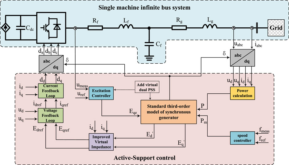
FIGURE 1. Overall control of the active-support new energy VSC unit.
In order to make the renewable energy generation VSCs have the characteristics of frequency and voltage regulation of synchronous generators, a standard third-order model of the synchronous generators is established according to the second-order rotator motion equation and first-order transient potential equation of the synchronous generators.
Compared with the traditional PLL phase-locked loop control strategy, the third-order model of the synchronous generator can produce a self-rotating angle, which does not depend on the change of power grid angular speed. The power angle step changes will not occur when the system is disturbed by power, effectively increasing the autonomy and immunity of the active support-controlled voltage source converter. The standard third-order model of the synchronizer is shown in Eq. 1:
where M is the virtual inertia; D is the damping coefficient; Δω is the angular velocity deviation of the rotor movement; Pm is the mechanical power; Pe is the electromagnetic power; δ power angle of the generator;
To ensure that the active support-controlled voltage source converter can Safe and stable operation limits the current out of limit behavior of the VSC during fault, so the virtual stator winding link is introduced, and the expression is:
where Edref is the direct axis voltage reference value; Eqref is the reference value for cross-axis voltage;
The control block diagram of the synchronous standard third-order model is shown in Figure 2.
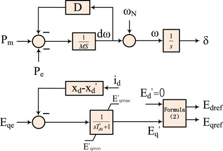
FIGURE 2. Standard third-order model of the synchronous generator.
The renewable energy units which used the active-support control can simulate the static frequency characteristics of the synchronous generators and achieve automatic allocation of unbalanced power among multiple machines in system frequency modulation, that is:
where fref is the frequency reference value; Pm is the power reference value; P0 is the active power output of the renewable energy unit; fmeas is the measured frequency; and Km is the droop coefficient of P − f.
The control block diagram of the governor is shown in Figure 3.
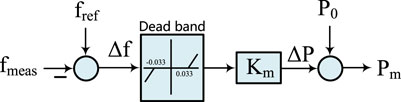
FIGURE 3. The block of speed controller.
The active-support control voltage source converter excitation regulator can automatically adjust the port voltage of the generator when an unbalanced power impact occurs in the system. In case of unbalanced power impact on the system, the active-support control voltage source converter excitation regulator can automatically adjust the port voltage of the generator, effectively improving the dynamic voltage stability of the system. At the same time, it can be simplified as the first-order inertial link with the voltage deviation as the input signal.
The expression is:
where Umeas is the active-support controlled voltage source converter outlet voltage; Uref is the voltage reference value; and ΔEf is the excitation voltage deviation. The control block diagram of the governor is shown in Figure 4.

FIGURE 4. The block of excitation controller.
The excitation part of the traditional Virtual Synchronous Generator (VSG) control uses the reactive power-voltage droop link, which can meet the voltage regulation requirements when the system has small disturbance, but when the system voltage drops greatly, the simple reactive power-voltage droop link cannot face the system voltage regulation requirements. Therefore, this article adds an improved virtual reactance based on the third-order model of the synchronous generator, which can enhance the reactive power support capacity of the new energy system and improve the low-voltage ride through capacity in case of fault. At the same time, when the system voltage drop is light, the renewable energy unit can produce active power as much as possible.
The improved virtual impedance model is as follows:
where Zf is the parameter of virtual impedance determined by calculation under different degrees of three-phase symmetric faults; Ig is the output current of the renewable energy unit; Kon is the virtual impedance triggered on factor; t is the current time; ts is the transient time adjustment factor from 0 to the maximum of the virtual impedance; and tc is the time when the measured instantaneous peak current exceeds the threshold.
At the moment of system failure, the output current of renewable energy unit jumps due to different degrees of voltage drop. On one hand, the output current of the renewable energy unit is less than 1 p.u.,which is the rated value of the output current under the standard unitary value. This moment, the virtual impedance does not start. On the other hand, the current value of these units is too large, which means that the current at this time has been converted into the form of impulse current, and the virtual impedance is introduced into the active support control strategy during the fault period. If the current value of dq axis is directly multiplied by the proportional coefficient, its value will produce an instantaneous impact in the voltage loop. To reduce these effects, the exponential adjustment factor named − (t − tc)/ts is set so that the virtual impedance value can quickly and smoothly reach the corresponding maximum virtual impedance value, which has the effect of steadily limiting the current while improving the reactive power output capacity of new energy units during failure.
Now we have a virtual impedance, but we need to know how the renewable energy unit can use it. Therefore, the virtual impedance triggered on factor Kon is introduced to determine whether a renewable energy unit enters the emergency voltage control mode or not. The virtual impedance trigger opening factor Kon is mainly determined by three parts. The first part is the size of the voltage
The second part is to determine the size of the KI factor by the current scalar unitary
where Igmax is the maximum current allowed by the inverters of new energy units. Generally, it is between 1.1–1.5 p.u. This article takes 1.2 p.u. as the reference. The third part is mainly to solve how to distinguish whether the system is in a failure state when the new energy unit is not full-blown or the influence of the failure is slight. The third part is the ratio of the output current of the new energy unit inverters before and after the failure to determine the size of KΔI:
From the Formulae 6–8, the virtual impedance trigger switch coefficient Kon is:
As shown in Figure 5, the renewable energy unit first identifies whether the virtual impedance triggered opening factor Kon is greater than or equal to 2. If it is greater than or equal to 2, the renewable energy unit enters the emergency voltage control mode and puts into the virtual impedance control link. To determine if the output current is greater than 1 p.u. in the KU process, and if the output current is greater than 1 p.u., the stable operation of the renewable energy unit in the low voltage traversal state is maintained. If the output current is less than 1 p.u., the renewable energy unit is released from the emergency voltage control mode, and the improved virtual damping control strategy is withdrawn from the operation.
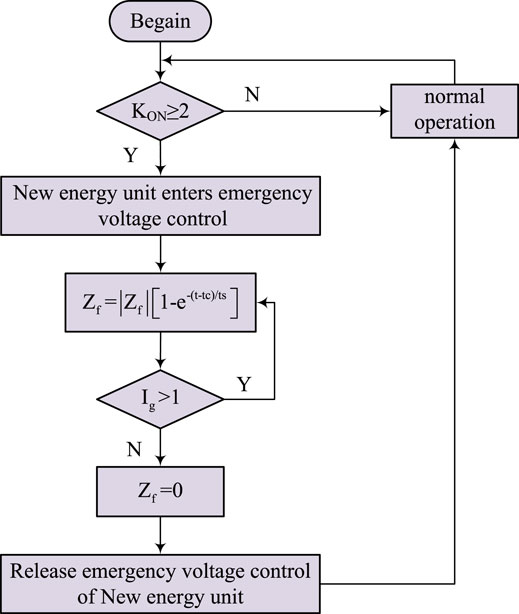
FIGURE 5. Flow chart of fault discrimination.
A virtual dual PSS method is presented to solve the power oscillation caused by the negative damped torque of the system. That is, the virtual excitation PSS and the virtual power angle PSS work together to further improve the damping characteristics of the system.
Assuming that the speed regulator does not participate in the operation, ignoring the effect of distributed capacitance on the line and line loss, the grid-connected voltage of the active support controlled voltage source converter is infinite system voltage U = Ug∠0° degrees. The Heffron– -Phillips model for a single machine infinite system is established as follows:
where K1∼K6 is the coefficients of the parameters related to the system structure and the static operating point.
This article mainly analyses the suppression methods of ACVSC (Active Support Controlled Voltage Source Converter) grid-connected electro-mechanical oscillation, without considering the influence of source-end characteristics and inverter element characteristics. Based on Formula 10, a Heffron–Phillips model of the active support control voltage source converter grid-connected system is obtained as shown in Figure 6.
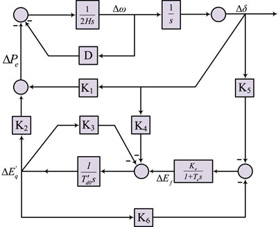
FIGURE 6. Grid-connected Heffron–Phillips model of voltage governor.
Additional PSS can select the angular speed deviation, frequency deviation, and power deviation of the rotor as input signals. In this article, angular velocity deviation is taken as input signal for the analysis. Figure 7 shows the additional virtual excitation PSS control block diagram.
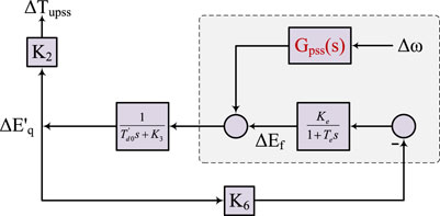
FIGURE 7. Additional virtual excitation PSS control block diagram.
As shown in Figure 7, the electromagnetic torques supplied by the additional virtual excitation PSS to the electromechanical oscillation circuit are:
By substituting the Laplacian operator s = jΩ and Δω = jΩΔδ for the previous formula, we can get:
Because the Te parameter of the exciter is very small and the transient time constant
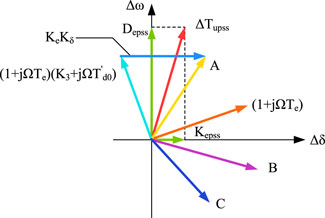
FIGURE 8. Virtual excitation PSS compensation torque vector diagram.
As shown in Figure 8, ΔTupss, additional torque, make vertical lines to the horizontal and vertical axis of Δω − Δδ in the first quadrant, which can be decomposed into the overlay of two orthogonal vectors, where Depss > 0, a positive additional damping moment can be provided to improve the damping characteristics of the system.
On the basis of virtual excitation PSS, this section puts forward the method of adding virtual power angle PSS. Due to the flexible configuration of power electronic equipment, virtual power angle PSS can divide the deviation of rotor angular velocity Δω into virtual power angles Δδ, which greatly improves the adjustment accuracy of the system. Figure 9 shows an additional virtual power angle PSS control block diagram.
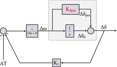
FIGURE 9. Additional virtual power angle PSS control block diagram.
As can be seen from Figure 9, the variation Δδ of the rotor motion angle consists of two parts. One part is obtained by integrating the angular velocity deviation Δω of the rotor, the other part is generated by the additional virtual power angle PSS link with gain factor KPss. The damping torque contributed by the additional virtual power angle PSS to the electromechanical oscillation circuit is divided into two parts, that is,
The total damping torque contributed by Virtual Power Angle PSS to electromechanical oscillation circuit ΔTδPSS is:
Based on Formula 14, a compensating torque vector graph as shown in Figure 10 can be drawn, where A is the phase of Fupss(s)Δδ denominator, B is the overall phase of Fupss(s)Δδ fraction. Like the virtual excitation PSS, the additional virtual power angle PSS can also provide a positive additional damping torque to the system.
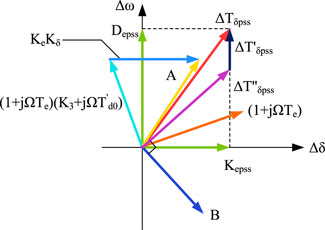
FIGURE 10. Virtual power angle PSS compensation torque vector diagram.
In summary, both the virtual excitation PSS and virtual power angle PSS have the effect of damping torque contributing to the electromechanical oscillation circuit of the system. Both the virtual excitation PSS and virtual power angle PSS take the angular velocity deviation of the rotor as input signals. The rotor angular velocity deviation is zero at a steady state and only plays a role in the dynamic process of the system. When the virtual excitation PSS and the virtual power angle PSS work together, not only will they not affect the stable operation of the original system, but also will further optimize and improve the dynamic damping performance of the system.
A two-machine system is built in the DigSILENT/PowerFactory simulation software. As shown in Figure 11, one of them is a 200 MW new energy unit with an active-support control, which has a virtual inertia factor H = 8 and a damping factor D = 3. The other 200 MW synchronous unit analyses the support capability of the two control strategies under active and reactive load disturbances. The validity of active support control strategy is verified by the comparative analysis. When the two-machine system runs to 301 s, a 25 MW active surge in the system load occurs. Figure 12 shows the active output curve of the active-support renewable energy unit when the active load increases suddenly.
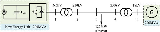
FIGURE 11. Simulation model diagram of the two machine system.
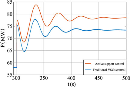
FIGURE 12. Active power output of new energy unit during sudden increase of active load.
The active power output of the renewable energy unit controlled by the V–Q droop voltage gradually increases from 58.36 to 73.56 MW when the load increases dramatically. But with the control of the active-support, it gradually increases from 58.36 to 78.64 MW.
On the other hand, as shown in Figure 13, the output reactive power of the renewable energy unit controlled by V–Q droop voltage gradually increases from 13.20 to 18.70 MVar during the reactive power surge of the load. The active power output of the renewable energy unit under the active-support control gradually increases from 13.20 to 23.86 MVar. It is not difficult to analyze that when the active load of the active-support renewable energy unit suddenly increases in the two-machine system, it bears more active load increase which not only meets the active demand of the system, but also indirectly meets the reactive demand of the system. The active-support renewable energy unit have significantly improved the active and reactive support capabilities in the system, and improved the system stability.
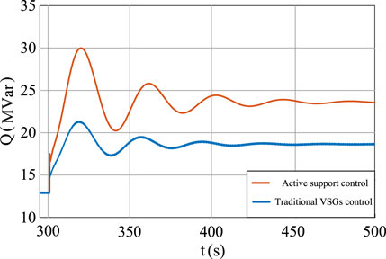
FIGURE 13. Reactive power output diagram of the new energy unit during sudden increase of active load.
Figure 14 shows the voltage of the grid-connected point of a permanent magnet wind generator when the active load increases sharply. The voltage at the grid connection point of the renewable energy unit controlled by the V–Q droop voltage regulation gradually drops from 1 to 0.9767 p.u. when the active power surge occurs, and then remains stable. The grid-connected voltage of the renewable energy unit under the active-support control stabilizes rapidly to 1 p.u. after short-amplitude oscillation, which ensures that the grid-connected voltage remains stable at the reference value. It shows that the renewable energy unit under the active-support control has better voltage regulation capability than the V–Q droop voltage control. In the case of active load disturbance, it has faster and more stable voltage support capacity and shorter voltage regulation time.
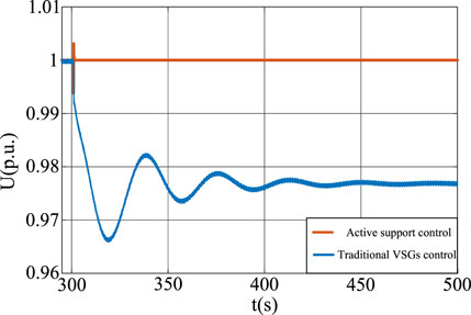
FIGURE 14. Voltage of new energy unit paralleling network point when the active load increases suddenly.
A typical IEEE Four-Machine-Two-Area System is built for analysis and validation. The structure of the system is shown in Figure 15. The system consists of two areas, the left area S and the right area A. Each of these areas has two generators nominally designated as 900 MVA. Generator 2 is replaced by the equal capacity active-support controlled voltage source converter. The two areas are electrically connected through 220 km double-circuit lines, each with a fixed load. Under the basic steady-state operation, the transmission power between the two regions is 400 MW.
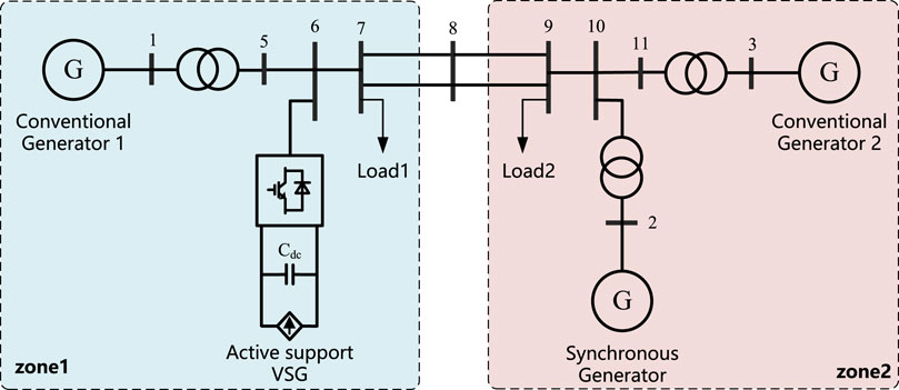
FIGURE 15. Four-machine two-zone system topology diagram.
To verify the reactive power and voltage support of the active-support renewable energy unit with virtual reactance control strategy in a regional power network in case of symmetric failure of the system, three-phase short circuit fault at node 8 between area S and area A were set up. The grounding reactance Lf is 10 Ω, and the Xfd in the active-support renewable energy unit is 0.037 p.u., aiming at the compared reactive power support capacity of area S and area A.
Compare the voltage values of 6 and 10 nodes in Figure 16. It is found that the voltage drop at 6 nodes of area S (containing active-support renewable energy unit) is significantly smaller than that at 10 nodes of area A coupling point. This indicates that area S has stronger reactive power support capability during the low voltage traversal, resulting in higher voltage values during failure. Area S is less affected by the fault and has strong anti-interference ability.
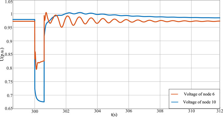
FIGURE 16. Comparison diagram of voltage change at coupling point in four-machine two-area system.
From Figure 17, it can be seen that G2 in area S assumes more reactive power, while G3 and G4 in area A assume similar reactive power because the system does not apply control strategy to the traditional synchronous generator. Therefore, on the basis of improving the regulation flexibility of the traditional synchronous generators and the continuous improvement of new energy grid connection scale, the system should make more use of the fast reactive power support capacity of active-support new energy units in the region during the fault. The voltage drop of each node in the guarantee area shall be minimized, and the synchronous generator in the area shall ensure the partial load operation in the system as much as possible.
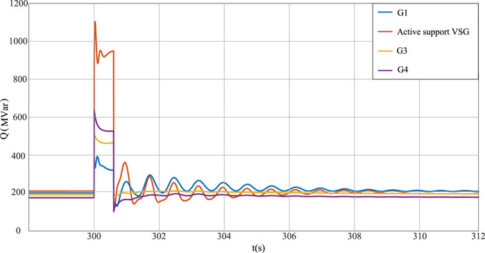
FIGURE 17. Change of output reactive power output of each unit in four-unit two-area system.
At t = 300 s, Load 1 in area S in Figure 15 sets a 10 percent load increase event. The output power of the active-support controlled voltage source converter is compared under four working conditions: no PSS, virtual excitation PSS, virtual power angle PSS, and virtual dual PSS. Figure 18 shows the output active power diagram of the active-support controlled voltage source converter.
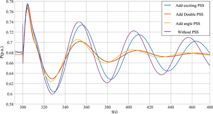
FIGURE 18. Active power output diagram of active-support controlled voltage source converter.
From the analysis in Figure 18, it can be seen that the output power of the active-support controlled voltage source converter is obviously compared under four working conditions. When PSS is not configured, the system’s damping performance is weakened due to the negative damping torque caused by the introduction of excitation link, and the output power oscillation of the active-support controlled voltage source converter is large. However, the effect of virtual excitation PSS with a single configuration is limited. After the virtual double PSS is added, the oscillation amplitude of the output power of the active-support controlled voltage source converter is further suppressed, and the time to reach a steady state output is shorter, and the damping performance of the system is further improved. Rotor angular velocity deviation under four operating conditions is shown in Figure 19.
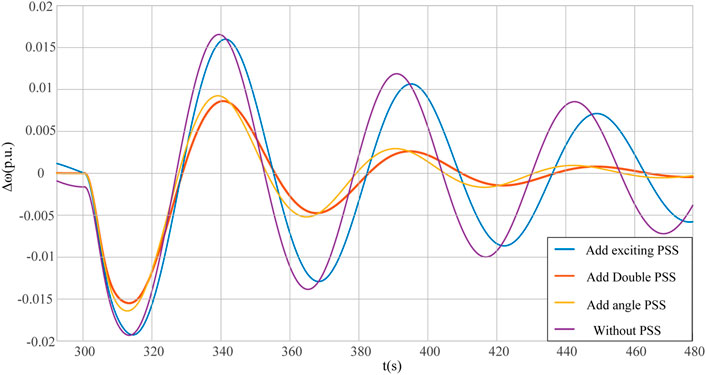
FIGURE 19. Rotor angular velocity deviation of active-support controlled voltage source converter.
As can be seen from Figure 19, under the conditions of virtual power angle PSS and virtual dual PSS, the deviation of the rotor angular velocity Δω will return to zero approximately after 200 s of disturbance. However, the angular velocity deviation between the PSS without configuration and the PSS with virtual excitation takes a long time to recover and shows a reduced amplitude oscillation state. When the angular velocity deviation of the rotator is restored to zero, the additional feedback signal from the dual PSS output is zero, and the damping torque provided to the electromechanical oscillation circuit is also zero. Therefore, the selection of angular velocity deviation of the rotor as the input signal of PSS will only play a role in the oscillation dynamic process of the system, and will not affect the stable operation of the original system. The oscillation characteristics of generator G1 and G4 under different operating conditions are shown in Figure 20.
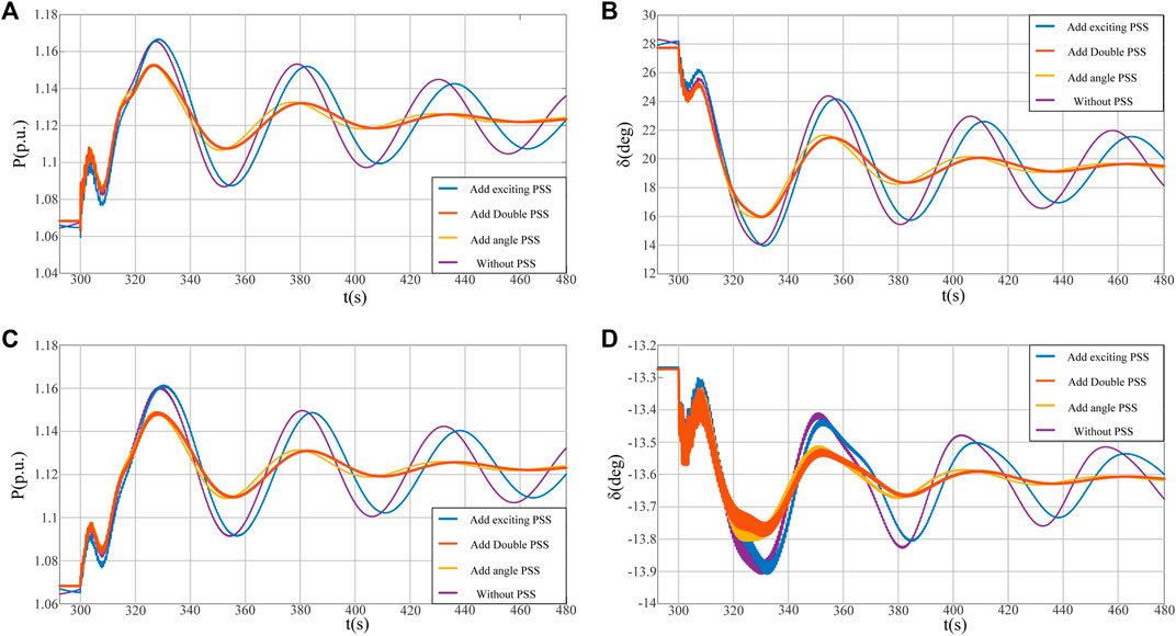
FIGURE 20. Power and relative rotor angle oscillation characteristics of generators G1 and G4.
Generator G3 was set as the reference generator, each generator unit takes into account the role of the speed regulator, and each synchronizer automatically allocates the unbalanced power during load disturbance. As can be seen from Figures 20A,C, the oscillation amplitude of power decreases significantly after the additional virtual excitation PSS or additional virtual power angle PSS. From Figures 20B,D, it can be seen that the maximum offset and oscillation amplitude of generator G1 and G4 relative to the rotor angle of the reference motor will also be reduced, which reduces the power oscillation on the transmission lines between the regions of the system. The system frequency oscillation characteristics under four different operating conditions are shown in Figure 21.
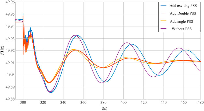
FIGURE 21. The system oscillation characteristics.
As can be seen from Figure 21, the virtual dual PSS configuration reduces the maximum depth of system frequency and the dropping rate is smaller than that of the virtual power angle PSS configuration. Under the conditions of virtual power angle PSS and virtual dual PSS, the system frequency restores to a stable state approximately 220 s after system power disturbance which effectively shortens the frequency adjustment time and has a better characteristic of damping the frequency oscillation of the system. PSS not configured and virtual excitation PSS configured continue to exhibit reduced amplitude oscillation, but the effect of damping oscillation with the virtual excitation PSS is better than that without PSS configured. In summary, the virtual dual PSS will effectively improve the frequency stability of the system after the disturbance under the interaction of power angle PSS and excitation PSS.
When t = 300 s, three-phase short-circuit fault is set at node 8 between area S and area A, and run to 300.6 s fault removal is performed to compare the effect of virtual double PSS oscillation suppression. The simulation results are as follows:
The output active and reactive power of the new energy unit under the virtual double PSS condition during the fault period are compared. As shown in Figures 22, 23, the virtual dual PSS can still suppress power oscillation and improve the recovery speed of the active and reactive power after a fault. This conclusion is consistent with the system perturbation.
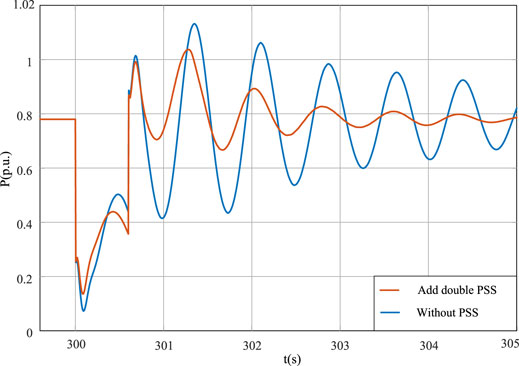
FIGURE 22. Active power output diagram of active-support controlled voltage source converter under the fault state.
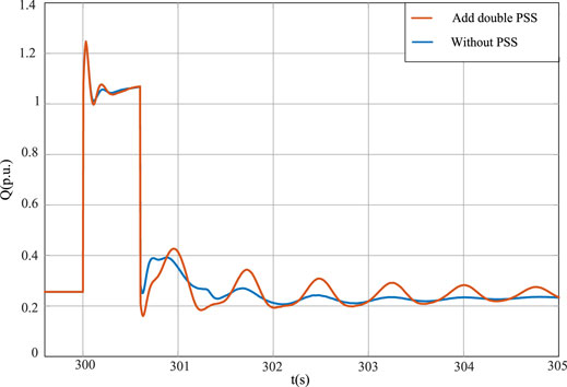
FIGURE 23. Output reactive power diagram of active-support controlled voltage source converter under the fault state.
It can be seen from Figures 24, 25 that the current and voltage oscillations can be suppressed by configuring the dual PSS during a fault. This improves the recovery speed of the output current and port voltage of the active-support controlled new energy unit, and improves the antidisturbance ability of the system. The simulation verifies the validity of the virtual dual PSS method.
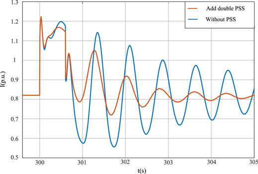
FIGURE 24. Output current diagram of active-support controlled voltage source converter under the fault state.
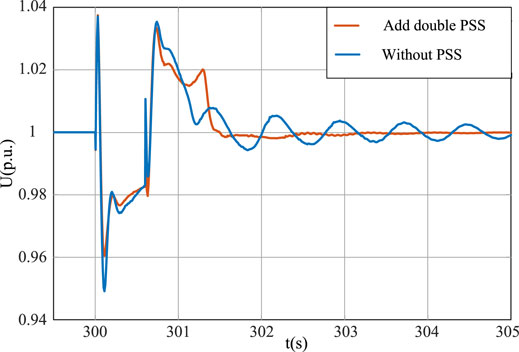
FIGURE 25. Port voltage diagram of active-support controlled voltage source converter under the fault state.
(1) This article presents an active-support control strategy based on a third-order model. By introducing the first-order transient voltage equation, the renewable energy unit is equivalent to a synchronous voltage source with the excitation control and speed control, which improve the frequency modulation capability and voltage support capability of the new energy system.
(2) In addition, in order to improve the low voltage traversal capability of the new energy units, an improved virtual impedance control strategy is presented. The short-circuit output current is limited by switching the virtual impedance, and the reactive power support capability during the fault is improved. It can also improve the low-voltage ride by the capacity of regional power grid to a certain extent.
(3) The problem of power oscillation during the grid connection of actively supported new energy units is studied. Through the analysis of damping torque method, the additional virtual excitation PSS and the virtual power angle PSS can contribute a certain damping torque to the electromechanical oscillation circuit of the system. By comparing the oscillation behavior of the system under four working conditions, it can be obtained that the configuring virtual double PSS can better compensate the negative damping torque of the system and thus better suppress the system oscillation.
The raw data supporting the conclusion of this article will be made available by the authors, without undue reservation.
CT and ZJ contributed to conception and design of the study. ZP performed the statistical analysis. CT wrote the first draft of the manuscript. CT, ZP, LD, LG, and LZ wrote sections of the manuscript. All authors contributed to manuscript revision, read, and approved the submitted version.
Authors CT was employed by the company Electric Power Research Institute of State Grid Liaoning Electric Power Co., Ltd. Authors ZJ, LD, LG, and LZ were employed by the company State Grid Liaoning Electric Power Co., Ltd.
The remaining author declares that the research was conducted in the absence of any commercial or financial relationships that could be construed as a potential conflict of interest.
All claims expressed in this article are solely those of the authors and do not necessarily represent those of their affiliated organizations, or those of the publisher, the editors and the reviewers. Any product that may be evaluated in this article, or claim that may be made by its manufacturer, is not guaranteed or endorsed by the publisher.
The author thanks the State Grid Liaoning technology project “Research on active support technology of high proportion renewable energy power system based on wind solar power generation inverter boost micro control” (Project No.2021YF-60).
Alipoor, J., Miura, Y., and Ise, T. (2013). “Distributed Generation Grid Integration Using Virtual Synchronous Generator with Adoptive Virtual Inertia,” in Energy Conversion Congress and Exposition (ECCE), 2013 IEEE. doi:10.1109/ecce.2013.6647309
Chong C.Huan Y. Zheng Z. Shengqing T. Rongxiang Z. CHENGChong, et al. (2015). Rotor Inertia Adaptive Control Method of Vsg. Automation Electric Power Syst. 8.
Driesen, J., and Visscher, K. (2008). Virtual Synchronous Generators. IEEE. doi:10.1109/pes.2008.4596800
Ekanayake, J., and Jenkins, N. (2004). Comparison of the Response of Doubly Fed and Fixed-Speed Induction Generator Wind Turbines to Changes in Network Frequency. IEEE Trans. Energ. Convers. 19, 800–802. doi:10.1109/tec.2004.827712
Frack, P. F., Mercado, P. E., Molina, M. G., Watanabe, E. H., De Doncker, R. W., and Stagge, H. (2015). “Control Strategy for Frequency Control in Autonomous Microgrids,” in IEEE International Symposium on Power Electronics for Distributed Generation Systems (IEEE J. Emerg. Sel. Topics Power Electron.), 3 1046–1055. doi:10.1109/jestpe.2015.2439053
Fu, X., Chen, H., Cai, R., and Yang, P. (2015). Optimal Allocation and Adaptive Var Control of Pv-Dg in Distribution Networks. Appl. Energ. 137, 173–182. doi:10.1016/j.apenergy.2014.10.012
Fu, X., Guo, Q., and Sun, H. (2020). Statistical Machine Learning Model for Stochastic Optimal Planning of Distribution Networks Considering a Dynamic Correlation and Dimension Reduction. IEEE Trans. Smart Grid 11, 2904–2917. doi:10.1109/tsg.2020.2974021
Ge, L., Xinfu, S., and Xiqiang, C. (2011). Improved Control Theory for Low Voltage Ride-Through of Permanent Magnet Synchronous Generator. Power Syst. Prot. Control. 39, 6.
Kehe, W., Jiye, W., Wei, L., and Yayun, Z. (2019). Research on the Operation Mode of New Generation Electric Power System for the Future Energy Internet. Proc. CSEE 14.
Lalor, G., Ritchie, J., Rourke, S., Flynn, D., and O’Malley, M. J. (2004). “Dynamic Frequency Control with Increasing Wind Generation,” in Power Engineering Society General Meeting.
Li, Y., Han, M., Yang, Z., and Li, G. (2021a). Coordinating Flexible Demand Response and Renewable Uncertainties for Scheduling of Community Integrated Energy Systems with an Electric Vehicle Charging Station: A Bi-level Approach. IEEE Trans. Sustain. Energ. 12, 2321–2331. doi:10.1109/tste.2021.3090463
Li, Y., Li, J., and Wang, Y. (2021b). Privacy-preserving Spatiotemporal Scenario Generation of Renewable Energies: A Federated Deep Generative Learning Approach. IEEE Trans. Ind. Inform.
Loix, T., Breucker, S. D., Vanassche, P., Keybus, J., and Visscher, K. (2009). “Layout and Performance of the Power Electronic Converter Platform for the Vsync Project,” in PowerTech, 2009 (IEEE Bucharest). doi:10.1109/ptc.2009.5282160
Lu, X., Wang, J., Guerrero, J. M., and Zhao, D. (2018). Virtual-impedance-based Fault Current Limiters for Inverter Dominated Ac Microgrids. IEEE Trans. Smart Grid 9, 1599–1612. doi:10.1109/tsg.2016.2594811
Qinglan, L., Wei, H., Lei, C., Chen, W., Ronghua, D., and Yong, M. (2020). Mechanism and Damping Analysis Method of Power System Stabilizer Affecting Frequency Oscillation. Automation Electric Power Syst. 44, 7.
Ruomei, D., Xiaocong, L., and Tingjie, P. (2019). Theory and Practice of Phase Compensation for Excitation System Using Pss-Avr Parallel Model. Electr. Switch 57, 6.
Shengwen, L., Guangqing, B., Shaowei, F., Jun, L., and Zhengyuan, L. (2011). A Low Voltage Ride-Through Control Strategy of Permanent Magnet Direct-Driven Wind Turbine with a Back-To-Back Pwm Converter. Large Mot. Technol. 5.
Shintai, T., Miura, Y., and Ise, T. (2014). Oscillation Damping of a Distributed Generator Using a Virtual Synchronous Generator. IEEE Trans. Power Deliv. 29, 668–676. doi:10.1109/tpwrd.2013.2281359
Tianwen, Z., Laijun, C., Tianyi, C., and Shengwei, M. (2015). Technology and prospect of Virtual Synchronous Generator. Automation Electric Power Syst., 11.
Xiangwu, Y., and Desheng, W. (2018). Power Frequency Control Scheme of Virtual Synchronous Generator Based on Three-Order Model. Power Elect. 52, 4.
Xiangwu, Y., and Jiaoxin, J. (2019). Decoupling Control of Primary Frequency Regulation and Rotational Speed Damping of Vsg. Power Syst. Tech. 10.
Xiaohui, Q., Lining, S., Yongning, C., Qiang, G., and Xiwang, X. (2018). Analysis of Inertia Support and Primary Frequency Modulation Function Positioning of Virtual Synchronous Generator in Large Power Grid. Automation Electric Power Syst. 42, 8.
Yang, X. Z., Su, J. H., Ming, D., Li, J. W., and Yan, D. (2011). “Control Strategy for Virtual Synchronous Generator in Microgrid,” in International Conference on Electric Utility Deregulation and Restructuring and Power Technologies.
Yilin, M., Huan, Y., Zisen, Q., Huanhai, X., and Junfei, H. (2021). Design Method for Improving Damping Characteristics of Virtual Synchronous Generator. Power Syst. Tech. 45, 1000–3673.
Yuntao, J., Yarong, M., and Zhinan, Q. (2020). Research on the Effect Mechanism of Virtual Synchronous Generator on Small-Signal Stability Based on Damped Torque Analysis. Proc. CSEE 10.
Zhenning, Z., Yongjun, H., Dongyuan, Z., Yufei, C., and Qingcai, Z. (2019). Research on Flexibility of New Generation Power System. Journal Electrical Engineering 014, 1–8.
Keywords: active-support control, third-order model, VSCs, virtual dual PSS, dynamic damping, additional impedance
Citation: Tianfeng C, Jun Z, Pengwei Z, Dianyang L, Gang L and Zhaowei L (2022) Active-Support Integrated Control Method for Renewable Energy Generation Voltage Source Converters. Front. Energy Res. 10:907787. doi: 10.3389/fenrg.2022.907787
Received: 30 March 2022; Accepted: 08 April 2022;
Published: 27 May 2022.
Edited by:
Xueqian Fu, China Agricultural University, ChinaCopyright © 2022 Tianfeng, Jun, Pengwei, Dianyang, Gang and Zhaowei. This is an open-access article distributed under the terms of the Creative Commons Attribution License (CC BY). The use, distribution or reproduction in other forums is permitted, provided the original author(s) and the copyright owner(s) are credited and that the original publication in this journal is cited, in accordance with accepted academic practice. No use, distribution or reproduction is permitted which does not comply with these terms.
*Correspondence: Chu Tianfeng, MTM0NTgzOTk3OUBxcS5jb20=
Disclaimer: All claims expressed in this article are solely those of the authors and do not necessarily represent those of their affiliated organizations, or those of the publisher, the editors and the reviewers. Any product that may be evaluated in this article or claim that may be made by its manufacturer is not guaranteed or endorsed by the publisher.
Research integrity at Frontiers
Learn more about the work of our research integrity team to safeguard the quality of each article we publish.