- College of Computer and Information Technology, China Three Gorges University, Yichang, China
The large-scale new energy sources such as photovoltaic power generation reduces the original damping and inertia of the power system, resulting in the oscillation of the system. Self-adaptive virtual synchronous generator (SDVSG) controlled grid-connected inverters can provide virtual damping and inertia to support the frequency and voltage of the grid. Combining SDVSG control with stand-alone PV systems, a mainstream solution is to configure energy storage systems for them. In this paper, a grid-connected PV storage system with SDVSG is proposed with coordination control; an adaptive variable-step conductivity increment method is adopted to achieve the maximum power point tracking (MPPT) for PV array, and variable domain fuzzy logic control methods of DC-DC converter are implemented as well. Finally, the simulation results prove the system has strong robustness and could handle the perturbations.
1 Introduction
With the rapid development of renewable energy technologies such as photovoltaic and wind energy, increasing distributed generator (DG) systems are connected to the conventional power system. Compared with the centralized power generation system based on the synchronous generator, the inverter-based DG system has flexible control and fast response but reduces the original inertia and damping characteristics of the power system (Alipoor et al., 2014; Pattabiraman et al., 2018). The rotational inertia and damping characteristics of synchronous generators play an important role in maintaining the frequency stability of power systems. However, the increasing penetration of DG has led to a decreasing proportion of installed synchronous generator capacity in power systems. The inertia and damping of the system are relatively weakened and the rotating reserve is relatively reduced, which poses a serious challenge to the stable operation of the power system (Alipoor et al., 2015; Bri -Mathias et al., 2020).
To improve the inertia and damping of power systems containing high permeability, DGs enhance their ability to suppress frequency fluctuations and improve the compatibility between inverters and the grid. The virtual synchronous generator (VSG) and its working principle were invented to improve the damping and inertia of the system (Zhong and Weiss, 2011; Zhong et al., 2014). The main idea of VSG technology is to make the inverter simulate the external characteristics of a synchronous machine, especially the frequency characteristics, using control algorithms. To equip the inverter with the frequency characteristics of a synchronous generator, the control algorithm is required not only to simulate the inertia of the rotor of the synchronous generator but also to connect the inverter with an energy storage device to consume the power required to simulate the kinetic energy change of the rotor of the synchronous generator. The current research on VSG is mostly based on the premise that the DC side of the inverter can provide a stable voltage source (European FP6 project workshop, 2011; Zhong and Weiss, 2011; Chen et al., 2011; D’Arco et al., 2013; Hua et al., 2017), which is not satisfied by the inverter powered by PV only. As the capacity and number of grid-connected PV systems increase, it is important to equip them with the characteristics of synchronous generators for the stable operation of the grid. The reduced-order small-signal closed-loop transfer function model is proposed and impedance analysis is developed to verify the stability of DC Microgrids (Rui et al., 2020; Wang et al., 2021). This reduced-order model is a novel preprocessing approach for the real-time simulation of large-scale converters which could be provided for DC microgrid designers. The adaptive error correction method for voltage source inverters severally is embedded into both the outer and inner prediction loop (Ma et al., 2021). The impacts of different negative factors can be simultaneously processed and corrected through an adaptive error correction strategy.
There are two dominant functions of energy storage in renewable energy plants (Wei et al., 2019): one is to suppress the fluctuation of grid-connected power of renewable energy plants (Sun et al., 2019; Al- Shetwi et al., 2020; Kulyk and Zgurovets, 2020); the other is to control the operation of plants and energy storage systems to make their output meet the requirements of a given generation output curve, to achieve the purpose of economic dispatch of plants (Li et al., 2011; Ma et al., 2017). There is little research on how to utilize energy storage to make distributed generation systems with synchronous generator characteristics. In (Liu et al., 2017; Ma et al., 2017), it is pointed out that the utilize of energy storage simulates the kinetic energy change of the synchronous generator rotor, but the control method of energy storage and renewable energy is not fully researched. In (Velasco de la Fuente et al., 2013), energy storage is selected as a backup for photovoltaic power generation, so that the distributed generation system can operate in both grid-connected and off-grid modes, but the inverter still adopts PQ and droop control and does not have synchronous generator characteristics. In the literature (Liu et al., 2015; Zhao et al., 2017), a storage inverter based on VSG control is connected in parallel to the AC side of the PV inverter to increase the inertia of the system, but it does not make the grid-connected PV inverter itself have synchronous generator characteristics. The VSG control in photovoltaic storage power systems is analyzed in (Zhong et al., 2022), but still regard the PV array and energy storage as equivalent DC voltage sources. The control of energy storage charging and discharging is normally neglected, resulting in large fluctuations in the state of charge (SOC), which results over charging or discharging to shorten the battery life. The concept of virtual inertia for frequency control of MGs via an extended VSG is introduced in reference (Fathi et al., 2018) the proposed control inherits both properties of inertia response of real SGs and fast dynamics of power electronic interfaces. The decentralized deep policy gradient algorithm is developed and employed to find the optimal control policy for VSG (Li et al., 2021). The optimal policy in a model-free fashion is obtained and validated with this adaptive control. In (Zhang et al., 2020), a coordinate control for PV-storage grid-connected system was proposed, in which the energy storage unit implements the MPPT control and the photovoltaic inverter implements a VSG algorithm providing inertial and primary frequency support for the microgrid. Whereas the conventional MPPT and VSG can hardly handle the new energy systems with random perturbations and high permeability.
To mitigate the issues of the current research, the proposed topology and its advanced control in this paper have the following main characteristics.
- The Adaptive variable-step conductivity increment method is implemented to achieve MPPT for PV arrays to avoid oscillation and untimely tracking near the maximum power point.
- The variable domain fuzzy logic control for DC-DC converter is designed to overcome large overshoot while quickly obtaining the desired reference voltage
- An adaptive virtual synchronous generator control strategy is developed for the power supply of the PV energy storage system to provide variable damping and inertia, improving the stability of the power supply.
- A coordinated control strategy is proposed to achieve grid-connected power leveling function, improve power generation efficiency and ensure DC bus voltage stability.
The rest of this paper is organized as follows: In Section II, the configuration of the system is presented and introduced; In Section III, the advanced control of the DC-AC inverter, DC-DC converter, ADVSG, and coordinate strategy is introduced, respectively; In Section IV, the proposed design and its control method are verified by the simulation experiment in MATLAB/Simulink. In Section V, conclusions are summarized and potential research directions are mentioned as well.
2 Coordinated PV and Battery Grid-Connected Systems
Conventional PV grid-connected systems are capable of maximum power tracking and grid-connected inverters. However, there are power leveling difficulties as well as low inertia and damping problems, which normally require external power sources for co-powering. In this section, the structure and characteristics of conventional PV grid-connected systems and energy storage-based PV grid-connected systems are introduced, respectively.
2.1 Conventional Grid-Connected PV Generator
The structure of two conventional PV grid-connected power generation systems is shown in Figure 1. In the direct PV system, the PV array is directly connected to the DC side of the inverter, as shown in Figure 1A. The power generated by the PV array is fed into the grid only through the DC/AC single-stage converter. The circuit of the two-stage grid-connected PV system is a two-stage power conversion circuit, as shown in Figure 1B. The front stage uses a boost converter to perform the step-up function of the output voltage of the PV array on the DC side and MPPT; the rear stage is a grid-connected inverter to perform the power conversion and grid-connected function, and the control of the boost converter and the inverter are independent of each other.
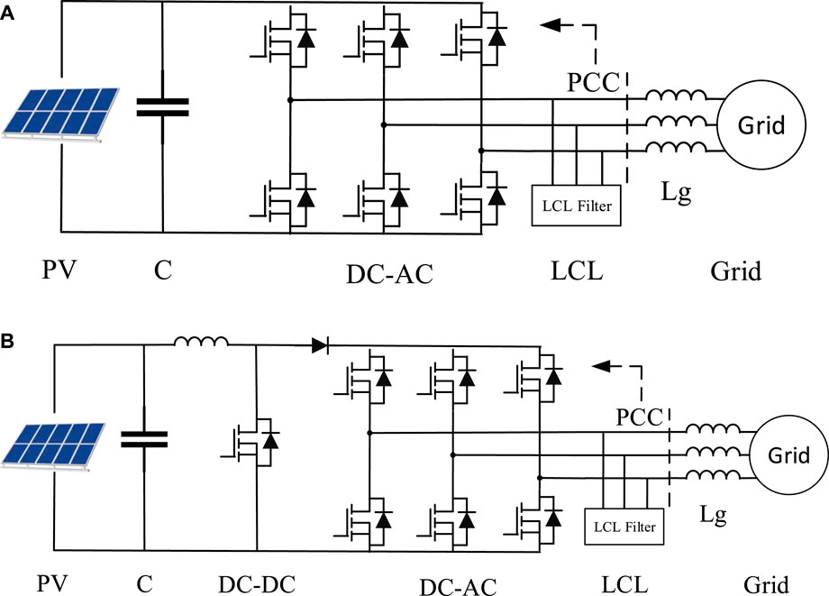
FIGURE 1. Structure of conversational grid-connected PV system. (A) Direct photovoltaic power generation system (B) Photovoltaic power generation system with DC-DC converter.
The inverter control of a conventional grid-connected PV system generally consists of an outer loop of DC voltage and an inner loop of active and reactive currents, which are externally reflected as current source characteristics. Since there is no energy storage device, the system output active power can only follow the power generated by the PV array, which is intermittent and fluctuating. The inverter output frequency is the grid frequency obtained from the phase-locked loop, which does not have inertia and damping characteristics. Therefore, conventional PV systems, whether single-stage or two-stage, are unable to provide frequency support for the grid.
2.2 Grid-Connected PV-Energy Storage System
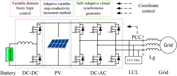
The structure of the grid-connected energy storage PV system is shown in Figure 2. The system includes the PV array, the energy storage device, the bidirectional DC-DC converter, the inverter, and its filtering circuit. The PV array is directly connected to the DC bus of the inverter and connected in parallel with the energy storage device with a buck/boost converter, and the energy is fed into the grid by the inverter based on VSG control. The control system is divided into three main parts: the coordination control unit, the DC-DC control unit, and the VSG control unit. On the one hand, the coordination control unit is responsible for searching the maximum power point voltage UMPP of the PV array and transmitting it to the DC-DC control unit as the DC bus voltage command value Uref, which controls the DC bus voltage according to the command, thus completing the MPPT of the PV array. On the other hand, the output power of VSG is adjusted according to the given rate command, while the reactive power command of VSG is given to control the charging and discharging power of energy storage, thus realizing the purpose of adjusting the SOC of energy storage. The VSG control unit implements the inverter to simulate the characteristics of the synchronous generator and to track the power command.
Compared with the traditional grid-connected PV power generation system, the energy storage PV grid-connected power generation system has the following features: 1) The energy storage device has an energy buffering effect so that the inverter output power does not have to be equal to the PV power, which not only reduces the fluctuation and intermittency of the grid-connected power but also meets the basic condition that the inverter simulates the rotor inertia of a synchronous generator. 2) The inverter in the grid-connected energy storage PV system is controlled by VSG, which simulates the characteristics of a synchronous generator and can realize the self-synchronous grid connection without the need for a phase-locking loop to detect the frequency and phase of the grid. 3) By simulating the synchronous generator characteristics, the energy storage PV grid-connected power generation system is externally characterized as a voltage source and has the ability of frequency inertia and damping frequency shift.
3 The Control of Grid-Connected PV Energy Storage System
3.1 The Control for the DC-DC Converter
The DC-DC control strategy aims to control the DC bus voltage to track the commanded value of Udc_ref given by the coordinated control unit and to control the charging and discharging of the energy storage device by controlling the inductor current of the buck/boost converter during the system operation. Therefore, the DC-DC control strategy adopts an outer loop of DC bus voltage and an inner loop of inductor current to control the buck/boost converter, as shown in Figure 3, in which a proportional-integral (PI) regulator is used for the outer loop of voltage and a proportional regulator is used for the inner loop of current. When the dc bus voltage rises, the bidirectional converter operates in buck mode to store energy for charging; when the dc bus voltage decreases, the bidirectional converter operates in boost mode to store energy for discharging. It is worth noting that the energy storage device stabilizes the DC bus voltage.
It is worth noting that by stabilizing the DC bus voltage, the energy storage device not only achieves the MPPT function but more importantly, enables the VSG to simulate the rotor inertia of the synchronous generator. Assuming that the output power of the PV array is constant when the disturbance reduces the frequency of the VSG, the grid-connected inverter simulates the process of releasing energy from the rotor of the synchronous generator, increasing the active power; this causes the DC bus voltage to decrease, and the energy storage discharges to stabilize the DC bus voltage and vice versa. Meanwhile the energy change of the energy storage simulates the increase or decrease of the kinetic energy of the synchronous generator rotor.
To ensure the normal operation of the system, the energy storage always maintain the DC bus voltage at a level not lower than the minimum voltage for successful inverter operation. The scaling factor and variable domain for fuzzy control provide a fast response to track the reference values. On the one hand, the maximum discharge power of energy storage is required to be no less than the short-term maximum output power of the inverter based on VSG control; on the other hand, during the frequency shift and PV power fluctuation, when the energy generated by the PV array is less than the output energy of the inverter, the output power of energy storage should be sufficient to make up the shortfall between them; and when the energy generated by the PV array is greater than the output energy of the inverter, which should have enough space to store the excess power.
3.2 DQ Decoupling for Photovoltaic Grid-Connected Inverters
This section will specifically introduce the principle of DQ-axis decoupling control of the inverter. The connection of the inverter to the grid can be approximated by the following equation.
Where the subscript abc denotes the column vector composed of the quantities corresponding to the three phases of abc; Uabc denotes the voltage of the inverter; iabc denotes the three-phase current, and eabc denotes the three-phase voltage on the net side. A Park transformation of Eq/(1) yields the following equation.
Where ω is the rotational angular velocity of the dq coordinate system in the Park variation. After the transformation, the active and reactive power output to the grid can be expressed as the following equation
Where P, Q represents the active and reactive power output to the grid, respectively.
The active and reactive power can be controlled separately by controlling the DQ axis current. Assuming that the reference values of id and iq (i∗ d, i∗ q) are known, then we can control the voltage output of the inverter so that id = i∗ d,iq = i∗ q. First, the Laplace transform of Eq. 2 is performed.
Where s is the Laplace operator. Vd and Vq are the DQ voltages of the inverter, so these are the two quantities that we can control. These two control quantities are of the following form.
Taking 5) into (4), the controlled quantity is obtained as
Eq. 6 shows that if the control variables could satisfy the relationship shown in Eq. 5, then the whole system can be represented as a second-order system shown in Eq. 6.
3.3 Self-Adaptive VSG Control
The control algorithm of VSG usually needs to calculate the output current or voltage of the synchronous generator in the current state based on a given mathematical model, and use it as a command to control the inverter to follow the command, to simulate the external characteristics of the synchronous generator. In this paper, the mathematical model of a synchronous generator is used as follows:
Where J is the rotor inertia of the synchronous generator, D is the damping factor, Tm and Te are the mechanical torque and electromagnetic torque of the synchronous generator, respectively, ωg is the rated angular frequency of the grid, and ω is the measured angular frequency.
The VSG control strategy is shown in Figure 4, where the filter capacitor voltage uabc is considered as the terminal voltage, and the output current iabc_ref of the synchronous generator in this state is calculated according to Eqs. 7–9 and used as the command value of the inverter output current iabc. To better simulate the synchronous generator characteristics, the inverter must track the commanded current iabc ref without static difference and quickly. Therefore, in this paper, the inverter is controlled in the synchronous coordinate system by using the angle θ solved by the model; at the same time, the capacitor voltage uabc is used as a feedforward quantity to improve the accuracy and speed of the VSG control system.
It should be noted that since the frequency regulation factor K and the damping factor D in the governor are the same for frequency regulation, this paper ignores the governor, i.e., Pref is equal to Pm, and compensates for its role by adjusting D.
The VSG connected in parallel with the grid must not only output active power to the grid but also can output a given amount of reactive power. In a conventional synchronous generator set, the reactive power can be regulated by adjusting the excitation current, i.e., the electric potential. Based on this principle, the variable D is adopted to obtain a better response of the characteristics of the excitation regulator. The difference between the commanded value of reactive power Qref and the actual value Q of the VSG is utilized as the input of the PI regulator, and adjusts the electric potential E to realize the closed-loop control of reactive power in grid-connected operation without differences.
3.4 Adaptive Variable-Step Conductivity Increment Method
The mainstream MPPT algorithms are the perturbation observation method and the conductance increment method. For the poor dynamic performance of the conductance increment method in the range of low slope, this paper adopts the conductance increment method based on adaptive variable step size. First, when the light and temperature are constant, the PV output power P is considered as a function of the port voltage U. The output power shows a variation of increasing and then decreasing with the process of increasing voltage. The differentiation process is given as follows:
Where I represents the current output from the PV. Eq. 10 could be transferred into (11).
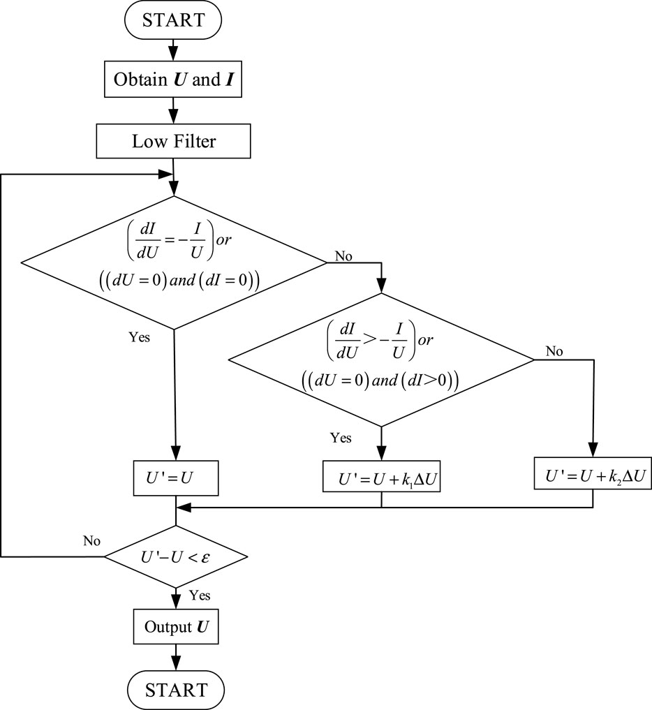
To reduce the disturbance of the sampling process, the system noise can be reduced by the low-pass filtering method. The control period is Ts, and the sampling period is Ts/10, then the average value obtained from ten samples can be used to input the system for processing.
The adaptive variable step conductance increment method is when the operating point voltage is less than the maximum power point, and the operating voltage should be increased to approach the maximum power point. Besides, due to the low slope of the curve, the tracking of the maximum power point is accelerated by using a larger step size, i.e., k1 takes a larger value. The voltage update process in the adaptive variable step size conductance increment method can be expressed as shown in Eq. 12
The flowchart of the proposed adaptive variable-step incremental method for MPPT is depicted in Figure 5.
3.5 The Optimized Coordinated Control
The task of the coordinated control unit is mainly two: first, to determine the maximum power point voltage UMPP of the PV array; second, to control the charging and discharging power of the energy storage to adjust the SOC of the energy storage. The VSG reactive power command Qref is given directly and the active power command Pref (i.e., Pm) is obtained by the coordinated control strategy. Based on the deviation of the charge/discharge power command value Pst_ref (Pst_ref > 0 discharge, Pst_ref <0 charges) from the actual value pst, the PI regulator adjusts the mechanical power Pm of the VSG, and the grid-connected inverter changes its output power according to the characteristics of the synchronous generator, thus controlling pst to track Pst_ref. For convenience, we assume that the SOC of energy storage is in the optimal range and set Pst_ref to 0. In this case, energy storage only compensates for the power imbalance between the PV array and VSG in the dynamic process, while maintaining a constant SOC in the steady-state. In practice, Pst_ref is adjusted by the energy management system according to the change of SOC. Figure 6.
The following is a detailed analysis of the process of controlling pst. The case of increasing light intensity is taken as an example: after the increase in light intensity, the PV power increases; at this time, the VSG output power remains unchanged, and the DC bus voltage increases; and the buck/boost converter will charge the battery to maintain a constant DC bus voltage, that is, pst < 0; then, Pst_ref -pst> 0, which makes the PI regulator output Pm increase, and according to the principle of synchronous generator, the VSG output power gradually increases; after the PV power is stabilized, as the VSG output power increases, the charging power pst will gradually decrease, until pst = Pst_ref = 0.
It can be seen that the coordinated control strategy can control pst and thus adjust the SOC of energy storage, which can avoid deep charging and discharging to shorten the battery life. Hence, the dynamic and static performance of the system is closely related to the switching frequency, synchronous generator model parameters, and controller parameters.
4 Simulation and Verification
To verify the feasibility of the above principle and the effectiveness of the system, the corresponding simulation model is built and experiments are conducted in MATLAB/Simulink environment. Section 4.1 introduces and explains the relevant parameters in the experiments, and describes the experimental procedure, and section 4.2 compares and analyzes the simulation results.
4.1 Parameters for Simulation
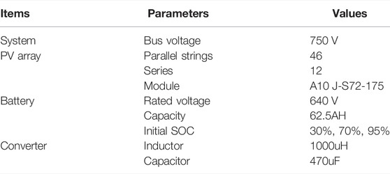
In this section, the parameters are presented in Table 1 as follows. the variation of the light intensity and the temperature is given in the following sections. Detailed descriptions of the dynamic response are provided as well.
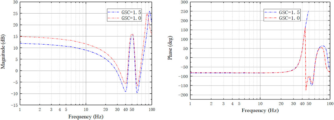
In a steady-state, the larger the active damping coefficient and the greater the phase margin of the system is indicating the system stability is improved. And the variation of the inverter inductance has a smaller impact on the system stability. While the increase of the filter capacitance and grid inductance leads to the decrease of the phase margin and reduces the system stability. The disturbance amplitude was taken as 0.5% of the rated voltage, and the frequency response was recorded for the reference voltage of 1.0 p. u. and 1.5 p. u., respectively, and the data were plotted as shown in Figure 7.
4.2 Results and Analysis
To further verify our design, three cases are set up to validate the proposed topology and its control. The descriptions of these three cases are given in Table 2.
4.2.1 Case 1
When the battery is overcharged (high SOC), the battery needs to be discharged with constant power, thus avoiding the battery from being damaged by overcharging. To obtain clear analysis results, constant light intensity was used in case1. three different temperatures were set in the PV module to verify the feasibility of constant power control. PV power, busbar voltage, and grid active and reactive power are recorded separately. The battery is in the discharge process and its output power and PV power together provide active power to the grid. The dynamic response of the above description is provided in Figure 8.
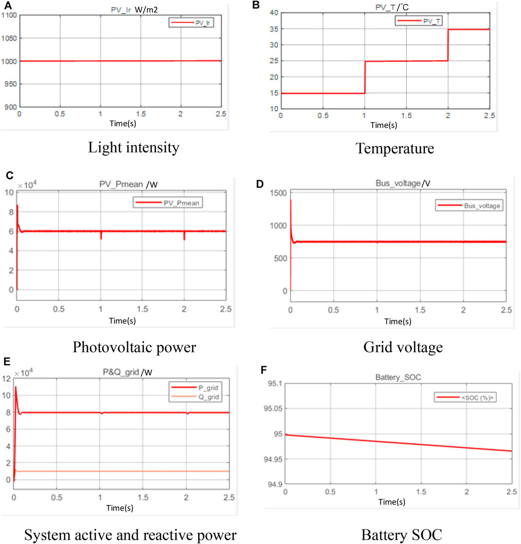
FIGURE 8. Dynamic response in case 1. (A) Light intensity (B) Temperature (C) Photovoltaic power (D) Grid voltage (E) System active and reactive power (F) Battery SOC.
4.2.2 Case 2
In case2, both light intensity and temperature are changed, and the PV module can obtain the maximum power by MPPT control. Accordingly, the output power of the PV module will change abruptly, when the energy storage system can provide a certain buffer. Compared with the power conversion of PV modules, the power of the grid changes more smoothly with energy storage support. The role of the inverter is to maintain a stable grid voltage at all times. The output power of the battery changes in response to sudden changes in the power of the PV module, thus smoothing the actual power received by the grid. The dynamic response of the above description is provided in Figure 9.
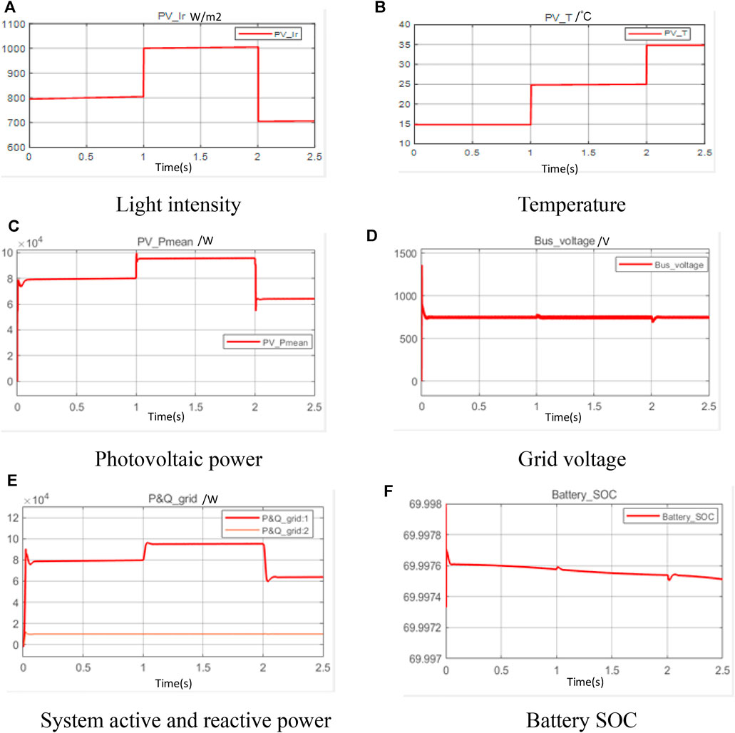
FIGURE 9. Dynamic response in case 2. (A) Light intensity (B) Temperature (C) Photovoltaic power (D) Grid voltage (E) System active and reactive power (F) Battery SOC.
4.2.3 Case 3
Case 3 uses the same light intensity variation and dimensional variation as case 2, and for a clear comparison between MPPT control and constant power control. Besides, the power control of the battery is protected in constant power charging mode. The dynamic response of the above description is provided in Figure 10.
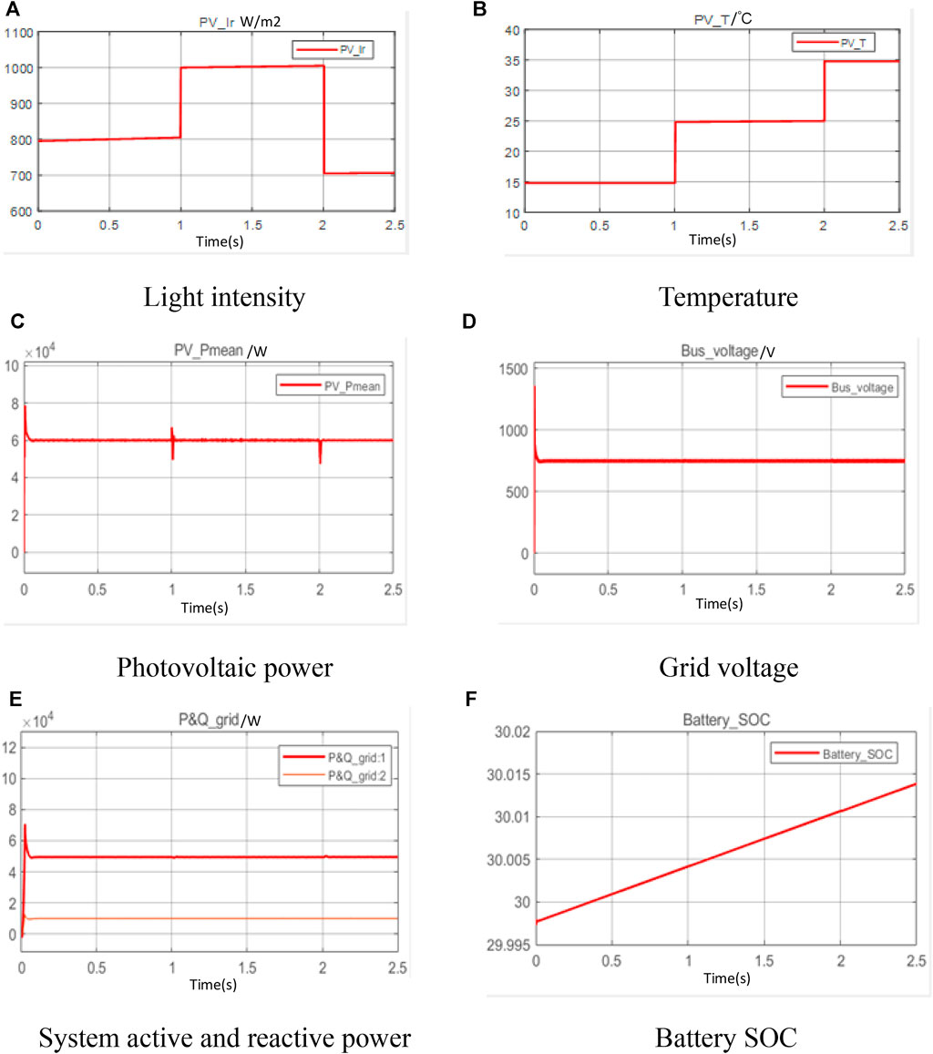
FIGURE 10. Dynamic response in case 3. (A) Light intensity (B) Temperature (C) Photovoltaic power (D) Grid voltage (E) System active and reactive power (F) Battery SOC.
The coordinate control proposed in this paper was validated through three test scenarios. Based on maintaining a constant grid voltage, the storage battery can smooth out the power variation of the PV; conversely, the PV system can also charge the energy storage system. Besides, the adaptive control adopted for MPPT and VSG significantly improved the stability of AC grid.
5 Conclusion and Future Work
In this paper, an energy storage type grid-connected photovoltaic power generation system with synchronous generator characteristics is researched. The hardware structure, control strategy, and mathematical model of the system are established. The influence of the main parameters on the stability and dynamic performance of the system is analyzed in detail. The simulation results not only verify the correctness of the fundamental working principle, but also prove the proposed control strategy can simulate the characteristics of synchronous power generation and maximum power tracking, and control energy storage charging and discharging, and the following conclusions are obtained: 1) The self-adaptive VSG control enables the interface inverter of PV power generation system to simulate the characteristics of synchronous generator, which has the ability of variable frequency inertia and damping frequency shift and can effectively improve the performance of the grid-connected distributed PV power generation system. 2) The coordinate control can switch the charging and discharging power of energy storage, adjust the SOC of energy storage, and provide the power required for throughput simulation of synchronous generator rotor kinetic energy changes, and can effectively avoid the impact of deep charging and discharging on energy storage life; 3) The adaptive variable-step conductivity increment method for MPPT of the PV array to improve the power generation efficiency but also smooths out the fluctuation of the grid-connected power of the PV system.
Due to the constraints of the research platform and some other factors, some simplification is made in the simulation verification, which will not affect the experimental conclusions. Based on this, some potential future research directions are summarized: 1) The variations of each battery in the array to achieve the synergistic operation of internal energy balancing and smoothing system power; 2) adaptive VSG control have variable damping and inertia, which should be optimized in real-time, and the application of deep learning will be considered in the future.
Data Availability Statement
The original contributions presented in the study are included in the article/Supplementary Material, further inquiries can be directed to the corresponding author.
Author Contributions
GC contributed to the conception and design of the study. YZ performed the statistical analysis and wrote sections of the manuscript. All authors contributed to manuscript revision, read, and approved the submitted version.
Conflict of Interest
The authors declare that the research was conducted in the absence of any commercial or financial relationships that could be construed as a potential conflict of interest.
Publisher’s Note
All claims expressed in this article are solely those of the authors and do not necessarily represent those of their affiliated organizations, or those of the publisher, the editors and the reviewers. Any product that may be evaluated in this article, or claim that may be made by its manufacturer, is not guaranteed or endorsed by the publisher.
References
Al-Shetwi, A. Q., Hannan, M. A., Jern, K. P., Mansur, M., and Mahlia, T. M. I. (2020). Grid-Connected Renewable Energy Sources: Review of the Recent Integration Requirements and Control Methods. J. Clean. Prod. 253, 119831. doi:10.1016/j.jclepro.2019.119831
Alipoor, J., Miura, Y., and Ise, T. (2014). Power System Stabilization Using Virtual Synchronous Generator with Alternating Moment of Inertia. IEEE J. Emerging Selected Top. Power Electron. 3 (2), 451–458. doi:10.1109/JESTPE.2014.2362530
Alipoor, J., Miura, Y., and Ise, T. (2015). Power System Stabilization Using Virtual Synchronous Generator with Alternating Moment of Inertia. IEEE J. Emerg. Sel. Top. Power Electron. 3 (2), 451–458. doi:10.1109/jestpe.2014.2362530
Bri-Mathias, S. H., Himanshu, J., Carlo, B. M.-A., and Gab-Su, S. (2020). Addressing Technical Challenges in 100% Variable Inverter‐Based Renewable Energy Power Systems. Wiley Interdiscip. Rev. Energ. Environ. 95, e376.
Chen, Y., Hesse, R., Turschner, D., and Hans-Peter, B. (2011). “Improving the Grid Power Quality Using Virtual Synchronous Machines,” in 2011 International Conference on Power Engineering, Energy and Electrical Drives (POWERENG), Malaga, Spain (IEEE), 1–6. doi:10.1109/PowerEng.2011.6036498
D’Arco, S., Suul, J. A., and Fosso, O. B. (2013). “Control System Tuning and Stability Analysis of Virtual Synchronous Machines,” in 2013 IEEE Energy Conversion Congress and Exposition (ECCE), Denver, USA (IEEE), 2664–2671. doi:10.1109/ECCE.2013.6647045
European FP6 project workshop (2011). VSYNC Project Workshop [EB/O–L]. Netherland: VSYNC Commission. Available at: http://www.vsync.eu/ (Accessed 15 3 2013).
Fathi, A., Shafiee, Q., and Bevrani, H. (2018). Robust Frequency Control of Microgrids Using an Extended Virtual Synchronous Generator. IEEE Trans. Power Syst. 33 (6), 6289–6297. doi:10.1109/TPWRS.2018.2850880
Hua, T., Yan, X., and Fan, W. (2017). “Research on Power Point Tracking Algorithm Considered Spinning Reserve Capacity in Gird-Connected Photovoltaic System Based on VSG Control Strategy,” in 2017 IEEE 3rd International Future Energy Electronics Conference and ECCE Asia (IFEEC 2017-ECCE Asia) (IEEE). doi:10.1109/ifeec.2017.7992368
Kulyk, M., and Zgurovets, O. (2020). “Modeling of Power Systems with Wind, Solar Power Plants and Energy Storage,” in Systems, Decision and Control in Energy I (Cham: Springer), 231–245. doi:10.1007/978-3-030-48583-2_15
Li, Q., Choi, S. S., Yuan, Y., and Yao, D. L. (2011). On the Determination of Battery Energy Storage Capacity and Short-Term Power Dispatch of a Wind Farm. IEEE Trans. Sustain. Energ. 2 (2), 148–158. doi:10.1109/tste.2010.2095434
Li, Y., Gao, W., Yan, W., Huang, S., Wang, R., Gevorgian, V., et al. (2021). Data-Driven Optimal Control Strategy for Virtual Synchronous Generator via Deep Reinforcement Learning Approach. J. Mod. Power Syst. Clean Energ. 9 (4), 919–929. doi:10.35833/MPCE.2020.000267
Liu, J., Miura, Y., and Ise, T. (2015). Comparison of Dynamic Characteristics Between Virtual Synchronous Generator and Droop Control in Inverter-Based Distributed Generators. IEEE Trans. Power Electronics 31 (5), 3600–3611.
Liu, J., Miura, Y., Bevrani, H., and Ise, T. (2017). Enhanced Virtual Synchronous Generator Control for Parallel Inverters in Microgrids. IEEE Trans. Smart Grid 8 (5), 2268–2277. doi:10.1109/tsg.2016.2521405
Ma, D., Cao, X., Sun, C., Wang, R., Sun, Q., Xie, X., et al. (2021). Dual-Predictive Control with Adaptive Error Correction Strategy for AC Microgrids. IEEE Trans. Power Deliv., 1. doi:10.1109/TPWRD.2021.3101198
Ma, Y., Cao, W., Yang, L., Wang, F. F., and Tolbert, L. M. (2017). Virtual Synchronous Generator Control of Full Converter Wind Turbines with Short-Term Energy Storage. IEEE Trans. Ind. Electron. 64 (11), 8821–8831. doi:10.1109/tie.2017.2694347
Pattabiraman, D., Lasseter, R. H., and Jahns, T. M. (2018). “Comparison of Grid Following and Grid Forming Control for a High Inverter Penetration Power System,” in 2018 IEEE Power & Energy Society General Meeting (PESGM), Portland, OR, USA, 5-10 Aug. 2018 (IEEE). doi:10.1109/PESGM.2018.8586162
Rui, W., Qiuye, S., Pinjia, Z., Yonghao, G., Dehao, Q., and Peng, W. (2020). Reduced-Order Transfer Function Model of the Droop-Controlled Inverter via Jordan Continued-Fraction Expansion. IEEE Trans. Energ. Convers. 35 (3), 1585–1595. doi:10.1109/TEC.2020.2980033
Sun, Y., Zhao, Z., Yang, M., Jia, D., Pei, W., and Xu, B. (2019). Overview of Energy Storage in Renewable Energy Power Fluctuation Mitigation. CSEE J. Power Energ. Syst. 6 (1), 160–173. doi:10.17775/CSEEJPES.2019.01950
Velasco de la Fuente, D., Rodríguez, C. L. T., Garcerá, G., Figueres, E., and Gonzalez, R. O. (2013). Photovoltaic Power System with Battery Backup with Grid-Connection and Islanded Operation Capabilities. IEEE Trans. Ind. Electron. 60 (4), 1571–1581. doi:10.1109/tie.2012.2196011
Wang, R., Sun, Q., Tu, P., Xiao, J., Gui, Y., and Wang, P. (2021). Reduced-Order Aggregate Model for Large-Scale Converters with Inhomogeneous Initial Conditions in DC Microgrids. IEEE Trans. Energ. Convers. 36 (3), 2473–2484. doi:10.1109/TEC.2021.3050434
Wei, Y., Dai, S., Yu, J., Wu, S., and Wang, J. (2019). “Research on Status and Prospects of Battery Energy Storage Stations on Energy Internet,” in 2019 IEEE 3rd Information Technology, Networking, Electronic and Automation Control Conference (ITNEC), Chengdu, China, 15-17 March 2019 (IEEE), 964–969. doi:10.1109/ITNEC.2019.8729063
Zhang, X., Gao, Q., Guo, Z., Zhang, H., Li, M., and Li, F. (2020). Coordinated Control Strategy for a PV-Storage Grid-Connected System Based on a Virtual Synchronous Generator. Glob. Energ. Interconnection 3 (1), 51–59. doi:10.1016/j.gloei.2020.03.003
Zhao, H., Yang, Q., and Zeng, H. (2017). Multi‐Loop Virtual Synchronous Generator Control of Inverter‐Based DGs Under Microgrid Dynamics. IET Generation, Transm. & Distribution Transmission Distribution 11 (3), 795–803. doi:10.1049/iet-gtd.2016.0645
Zhong, C., Li, H., Zhou, Y., Lv, Y., Chen, J., and Li, Y. Virtual Synchronous Generator of PV Generation without Energy Storage for Frequency Support in Autonomous Microgrid. Int. J. Electr. Power Energ. Syst. 134 (2022), 107343.
Zhong, Q.-C., Nguyen, P.-L., Ma, Z., and Sheng, W. (2014). Self-Synchronized Synchronverters: Inverters without a Dedicated Synchronization Unit. IEEE Trans. Power Electron. 29 (2), 617–630. doi:10.1109/TPEL.2013.2258684
Keywords: new energy grid connection, photovoltaic, maximum power point tracking, energy storage, coordinated control, virtual synchronous generators, adaptive variable-step conductivity increment method
Citation: Zhu Y and Chen G (2022) Advanced Control for Grid-Connected System With Coordinated Photovoltaic and Energy Storage. Front. Energy Res. 10:901354. doi: 10.3389/fenrg.2022.901354
Received: 21 March 2022; Accepted: 11 April 2022;
Published: 05 May 2022.
Edited by:
Rui Wang, Northeastern University, ChinaCopyright © 2022 Zhu and Chen. This is an open-access article distributed under the terms of the Creative Commons Attribution License (CC BY). The use, distribution or reproduction in other forums is permitted, provided the original author(s) and the copyright owner(s) are credited and that the original publication in this journal is cited, in accordance with accepted academic practice. No use, distribution or reproduction is permitted which does not comply with these terms.
*Correspondence: Guanhua Chen, MjAxOTEzNzEzMUBjdGd1LmVkdS5jbg==
 Yujie Zhu
 Guanhua Chen