 Jingying Liu
 Yao Min3
 Jian Gao
 Jing Zhou
- 1College of Electrical Engineering, Zhejiang University, Hangzhou, China
- 2State Grid Zhejiang Hangzhou Electric Power Co., Ltd., Hangzhou, China
- 3Qiantang District Branch, Zhejiang Dayou Group Co., Ltd., Hangzhou, China
- 4Polytechnic Institute, Zhejiang University, Hangzhou, China
Wireless Power Transfer (WPT) technology has been applied to electric vehicles (EVs), for its convenience, safety, and high reliability. However, for the traditional single-transmitter-single-receiver WPT system, due to its uneven electromagnetic field distribution, the power transfer capability and the anti-offset performance are always insufficient. The multi-transmitter-multi-receiver (MTMR) WPT system based on modular inverters with coils can not only improve the transmission power of the system but also boost the system’s anti-offset ability due to its more uniform magnetic field distribution. In this study, the topology and transmission characteristics of the MTMR WPT system are discussed accordingly: 1) A decoupling method of transmitting coil based on capacitance compensation is proposed, and the particle swarm optimization algorithm is used to derive the optimal design scheme of magnetic coupling coil. 2) A phase-shifting control strategy is proposed to realize the phase synchronization and current sharing control of coil current at each transmitter. Finally, the simulation and experimental results show that the modular wireless power transfer system with multiple transmitters and multiple receivers has strong power transmission capability and anti-offset performance.
1 Introduction
The development of wireless power transfer (WPT) provides new solutions for certain special occasions. Featuring safe, reliable, and highly-flexible, WPT is widely used in medical wearable devices, portable mobile electronic products, electric vehicles (EVs), and many other fields (Musavi and Eberle, 2014; Deflorio et al., 2015; Hasanzadeh and Vaez-Zadeh, 2015; Riehl et al., 2015; Zhang et al., 2019; Zhou et al., 2020a; Zhou et al., 2021). In addition, with the development of intelligent driving and automatic parking technology, automatic and intelligent charging solutions with no human interference will be indispensable technology in the future, and there are several design rules to optimize the transmission efficiency of the system (Hasanzadeh et al., 2012). Due to the characteristics of plug-less, automatic, and superior operability (Wu et al., 2010; Zhou et al., 2020b; Ming et al., 2021), the WPT technology will be an indispensable part of the upcoming intelligent transportation system. However, because of the uncertainty of the coils’ location, the offset between the transmitter and receiver coils will inevitably reduce transmission efficiency (Kim et al., 2017; Li Y. et al., 2019). Therefore, the offset problem is the fundamental problem remaining to be solved, and an appropriate strategy which can adaptively solve the offset problem will promote the application and development of WPT systems in the EVs.
In order to alleviate the decrease in transmission efficiency caused by the position offset between the coils, adjusting the structure of the coils is one of the major methods utilized. On one hand, there is still space for the improvement of a single modular coil structure. Professor John T. Boys proposed a bipolar rectangular flat coil (Double D) (Budhia et al., 2011) and a multi-layered coil structure on an E-type iron core (Elliott et al., 2010), which can improve the transmission efficiency and stability of the system under coil offset. On the other hand, as several multi-coil coupling structures have been used in WPT systems, they guide solving the misalignment problem. In some studies, the multi-coil structure is used to improve transmission efficiency (Seo, 2019; Lee and Lee, 2020; Pries et al., 2020). For example, an approximate solution for the arrangement of coils to achieve maximum efficiency in a multi-coil coupling system is proposed and experiments have verified its properties (Lee and Lee, 2020). The anti-misalignment performance of the WPT system can be improved with a multi-coil structure (Lee and Lee, 2020; Shen et al., 2022). In (Lee and Lee, 2020), a neural network method to model the propagation of magnetic resonance in multiple-input-multiple-output (MIMO) is proposed and used to reduce the impact of the offset problem. Additionally, a receiver position estimation method for multi-transmitter WPT systems using the machine learning method is proposed, and it is verified in an experiment that the system efficiency maintains around 90% even with the misalignment (Shen et al., 2022). Moreover, the geometrical design of the coils has also received attention in recent years. An omnidirectional energy harvester with a multi-coil structure is proposed and analyzed to avoid coil misalignment (Tan et al., 2016). The cylinder-shaped coils in a multi-coil WPT system is investigated and the system realizes stable output power within the full range of angular misalignment (Han et al., 2019). Therefore, it is proposed that the WPT system with multiple coils has great potential and future application (Cheng et al., 2019).
However, the application of the multi-coil WPT system still faces many difficulties, especially when applied to EVs. Even though there are a lot of literature studying the multiple coil WPT systems, they mainly focused on the MIMO WPT system rather than multi-transmitter-multi-receiver (MTMR) system, while the MIMO WPT system features multiple power outputs for different loads (Vu et al., 2017; Vu et al., 2019; Vu et al., 2020). In (Vu et al., 2019), the authors propose a multiple output WPT system, and experimental results with the total output power of 1.5 kW are provided, but the anti-offset performance is not the main research objective. Moreover, low power WPT systems (usually <100 W) have higher degrees of freedom in design, which come in a variety of geometries and some geometries (e.g., cylindrical, spherical, etc.) have good anti-offset performance (Tan et al., 2016; Han et al., 2019). However, in the scenario of EV charging, the shape of the coils is limited by the vehicle chassis. Without particular anti-offset design consideration, the wireless charging efficiency will drop significantly when misalignment happens. As the MTMR WPT system, is different from the widely studied single-transmitter-single-receiver (STSR) WPT system, there are still many uncertainties that need to be further clarified (Bandyopadhyay et al., 2019; Li H. et al., 2019; Lee et al., 2020). On the other hand, the MTMR WPT system commonly suffers from a cross-regulation problem, in which the variation in voltage or power from one output channel affects the stability of the others (Zhang et al., 2021). Moreover, the compensation network is important for the system, and (Hasanzadeh and Vaez-Zadeh, 2013) have carried out a detailed analysis of the compensation of the STSR system. But due to the special topology of the MTMR system, the compensation capacitance of the system still needs carefully analyzed and calculated. When designing an MTMR magnetic coupling structure, it is necessary to comprehensively consider the anti-offset performance as well as the cross-coupling effect of the system.
In order to address the aforementioned problems, first, a theoretical model of the MTMR WPT system for EVs is proposed in this study. The decoupling method of multiple transmitter coils based on compensation capacitors is proposed. Afterward, a coil optimization scheme based on the particle swarm optimization (PSO) algorithm (Clerc and Kennedy, 2002) is proposed, and the actual parameters are taken as an example to describe the system setup in detail. And a decoupling method for active and reactive currents of multiple transmitter coils is studied and used in the phase-locking and current-sharing control strategies. Then, a 3.3 kW experimental platform based on multiple inverters in parallel with three transmitters and three receivers is built to verify the theoretical analysis. Finally, the transmission efficiency and anti-offset performance of the system are verified when using the proposed control strategy. The proposed method provides an accurate and suitable approach for the WPT system with multiple inverters in parallel and the design of the magnetic coupling structure of the MTMR coupling structure.
2 Theoretical analysis of multi-transmitter-multi-receiver wireless power transfer system
2.1 Multi-transmitter-multi-receiver wireless power transfer system based on DS-LCC compensation network
The structure of the proposed MTMR WPT system using double side LCC (DS-LCC) compensation topology is shown in Figure 1. There are three transmitter coils and three receiver coils in the MTMR WPT system, and there is an independent LCC compensation network with an independent inverter before each coil to provide high-frequency current. The receiver with the LCC compensation network connects in parallel with an independent rectifier to provide power for the load. In the DS-LCC compensation network, when the mutual inductance value of the system is stable, the current flowing through the load maintains constant. The transferred power of the MTMR WPT system is effectively increased because of its anti-offset properties.
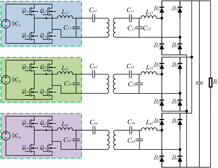
FIGURE 1. MTMR WPT system with DS-LCC compensation topology.
The equivalent circuit of the MTMR WPT system is shown in Figure 2. Ui is the source of each inverter. Li1, Li2, Ci1, Ci2, Cpi, and Csi are the compensation inductance and capacitance of each LCC compensation network. Lpi and Lsi are inductance of the coupled coil. In addition, since there is a coupling mutual inductance between every coil, Mxx_ij is defined as the mutual inductance (x = p (transmitter) or x = s (receiver)). Uxxi is the induced voltage generated between coils. According to Kirchhoff’s Law, the voltage can be expressed as:
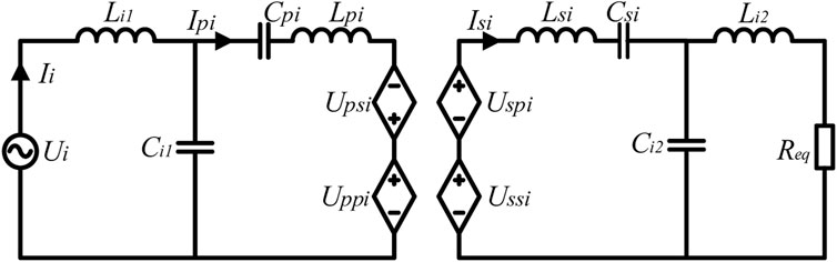
FIGURE 2. Equivalent circuit of the MTMR WPT system.
Based on the previous analysis, it is obvious that the current flowing through the coils is still constant. However, the output current of the inverter is expressed as:
It can be seen that the output current of the inverter will increase with the mutual inductance between transmitter coils. Therefore, additional series capacitors have to be added to achieve decoupling between the transmitter coils. The designed equivalent circuit of the MTMR WPT system with compensation capacitors is shown in Figure 3. In order to cancel the corresponding induced voltage, the added series compensation capacitance is expressed as:
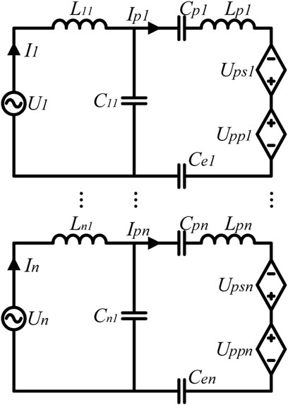
FIGURE 3. Equivalent Circuit of MTMR WPT System with Capacitance Compensation. In this picture, there are n pairs of transceiver coils.
In each transmitter LCC compensation network, the compensation capacitor in series with the coil is:
The induced voltage generated in the coils of the cross-coupling inductance between the transmitter coils can be eliminated. The compensation capacitor reduces the output current of the inverter and provides a favorable guarantee for the development and design of the MTMR WPT system.
2.2 Optimal design of coupling structure
In order to improve the transmission power and efficiency of the system, a WPT system with three transmitter coils and three receiver coils is taken as the research objective to analyze the mutual inductance and misalignment of MTMR coils. The plane layout of the circular multi-coil is shown in Figure 4. The coupling between each two receiving coils or transmitting coils can be decoupled so that their mutual inductance does not have to be concerned. When there is an offset between the transmitter and receiver coils, the mutual inductance between every two coils can be obtained as:
where rij is the distance between the center points of the two coils. Nx (x = i or j) is the number of turns of the coil, and rx (x = i or j) is the radius of the coil.
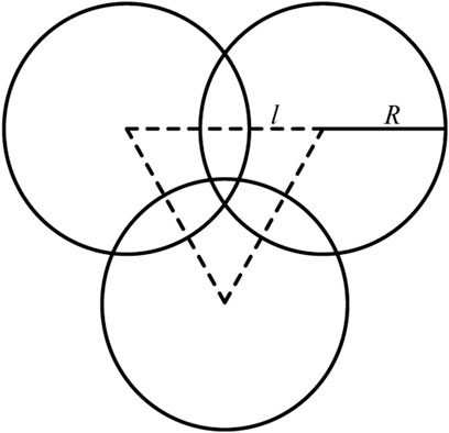
FIGURE 4. The plane arrangement of three circular coils.
Assume that the current flowing through one of three coils is
For the DS-LCC compensation network, the receiver output current is constant, so the total current
Therefore, the influence of the offset on the mutual inductance can be evaluated by the sum of mutual inductance (
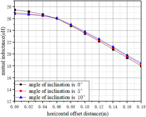
FIGURE 5. The mutual inductance offset characteristics of MTMR coils.
In order to balance the transmission efficiency and anti-offset performance of the MTMR WPT system, the PSO algorithm (Hasanzadeh and Vaez-Zadeh, 2013) is used to reasonably allocate the parameters of the system to find the optimal parameter setup of the system. The optimization goal can be summarized in the following three aspects: efficiency, anti-offset performance, and cost of the MTMR WPT system. The evaluation standard of the anti-offset performance is that under the same coil offset, the higher efficiency of the system equals better performance. The optimization conditions include: the current of each coil is less than the rated current I0, and the total outer diameter of the multiple coils is less than the radius limit r0. Furthermore, the efficiency of the WPT system is related to the mutual inductance and internal resistance between the coils. Therefore, the optimization goal can be written as:
where
2.3 Transmitter current synchronization strategy
In the actual WPT system, due to the inconsistent parameters of each element in the circuit, it is difficult to equalize the inductance and capacitance of each resonance compensation. As a result, assume that the tolerance between each element is α, according to Figure 4, the actual parameter is obtained as:
The difference between the transmit coil currents can be derived from Kirchhoff’s law:
where A and B are expressed by mutual inductance and α. As can be seen from Eq. 10, there is a certain difference in the current through each transmitting coil, and the vector diagram of the current flowing through each coil is shown in Figure 6A. There are differences in both amplitude and angle in the current vector diagram. However, when there is no difference in the system or the difference is minimized according to the control strategy, the current distribution shown in Figure 6B can be achieved. In this case, the current through each coil can be kept consistent in both phase and amplitude, and there is no reactive power. The losses caused by reactive currents in the compensation network will be reduced by the synchronization strategy.
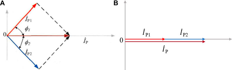
FIGURE 6. Current vector diagrams. (A) The currents are not synchronized. (B) The currents are synchronized.
In order to improve the output power, reduce the power loss and achieve effective capacitance compensation, a decoupling algorithm based on active and reactive currents is proposed. The algorithm can synthesize the current direction as the reference direction, and decompose the vector of each coil current into active current and reactive current respectively. A vector diagram of the active and reactive currents decomposed by the coil current is shown in Figure 7.
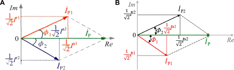
FIGURE 7. The vector diagram of currents decomposed by the coil current. (A) The active currents decomposed diagram. (B) The reactive currents decomposed diagram.
First, assume that the resultant current is the reference signal. Then the kth coil current can be expressed as
In fact, the virtual can be used to indicate the consistency of the direction and magnitude of the coil current in practice. Then multiply the ip and the virtual components, and eliminate the doubled signal in the result:
The resultant current amplitude
The magnitude can be expressed as:
In the control strategy, when there is parameter deviation in the circuit, the working state of the inverter (i.e., the phase and amplitude of the fundamental voltage output by the inverter) can be adjusted to compensate for the differences. In addition, the inverter phase and duty cycle can be adjusted according to the active and reactive components in the coil current. The transmitter’s current synchronization strategy will provide effective detection values for subsequent phase locking and current sharing. Compared with the zero-crossing comparator, the algorithm requires less accurate sampling of the current, so it is more suitable for high-frequency and high-power power occasions.
3 Experimental verification
In order to verify the proposed optimal design and control method of the MTMR WPT system, according to the topology shown in Figure 1, the experimental platform shown in Figure 8 is established. The experimental device includes three inverters, a Figure 8 control board, and the coupler. The control board provides drive signals for the three inverters simultaneously and realizes the phase synchronization and current sharing strategy of each transmitter coil current. After the receiver passes through the LCC compensation network, there are three different rectifiers connected in parallel, and provides stable power for the resistive load.
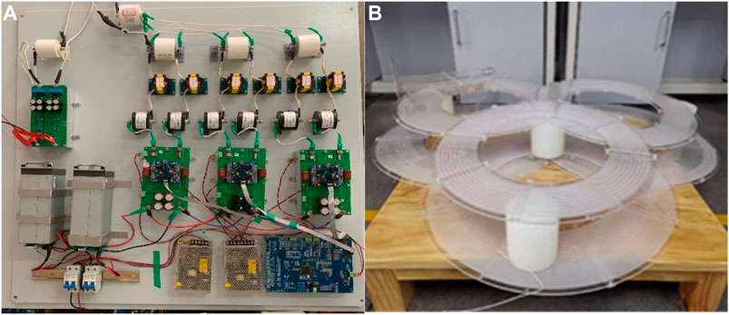
FIGURE 8. The proposed experimental system. (A) Three inverters and a control board. (B) The MTMR coupling structure.
3.1 Determination of coupling structure parameters
Combined with the actual requirements of the WPT system for EVs, the coupling structure and its parameters are designed according to the coupling structure optimization algorithm proposed in Section 2. First, the operation frequency of the proposed MTMR WPT system is 85 kHz, and the outer dimension radius of the coil is less than 1 m. In addition, according to the parameters of Litz wire, the constraints such as wire diameter are formulated. Then, the conditions and functions such as mutual inductance and internal resistance are brought into the optimization algorithm. The Pareto frontier based on multi-objective optimization is shown in Figure 9. It can be seen that when the number of turns of the coil is fixed, the small difference in the coil radius does not change the system efficiency intensely. When the coil radius is constant, the number of turns of the coil will have a great influence on the efficiency and cost. The optimization result on coil parameters is shown in Table 1.
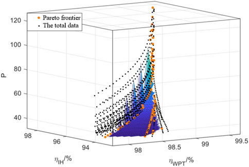
FIGURE 9. The proposed experimental system.
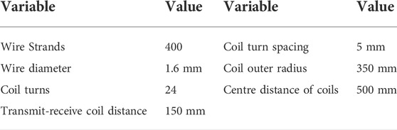
TABLE 1. Parameters of the MTMR WPT system.
Based on optimization results, finite element analysis is carried out to evaluate the magnetic field distribution for two cases: no offset between coils and 10 cm offset between coils. The simulation result is shown in Figure 10. When there is no offset, the magnetic field distribution is relatively uniform, but with a horizontal offset between coils, the magnetic field distribution will be distorted, and it is more distinct in the edge area of coils. For example, there is a point A in Figure 10, and the magnetic field around point A is very different in Figures 10A, B. Moreover, the parameters of the system can be measured from the simulation, such as the self-inductance, internal resistance, and mutual inductance.
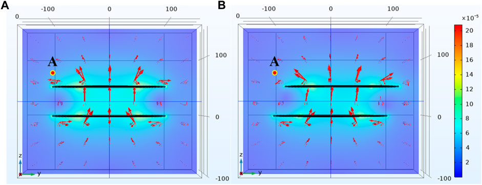
FIGURE 10. The magnetic field simulation results. (A) The alignment situation. (B) The offset situation.
Finally, the transmitter and receiver coils are wound according to the optimization results, as shown in Figure 8B. The self-inductance and mutual inductance of the coils were measured using an impedance analyzer. The comparison between the experimental results and the simulation results is shown in Table 2. It can be seen that the WPT system with MTMR coils can obtain higher coupling coefficients even in the occurrence of offset, which helps to achieve higher transmission efficiency. And the actual measured values are basically consistent with the simulation results.
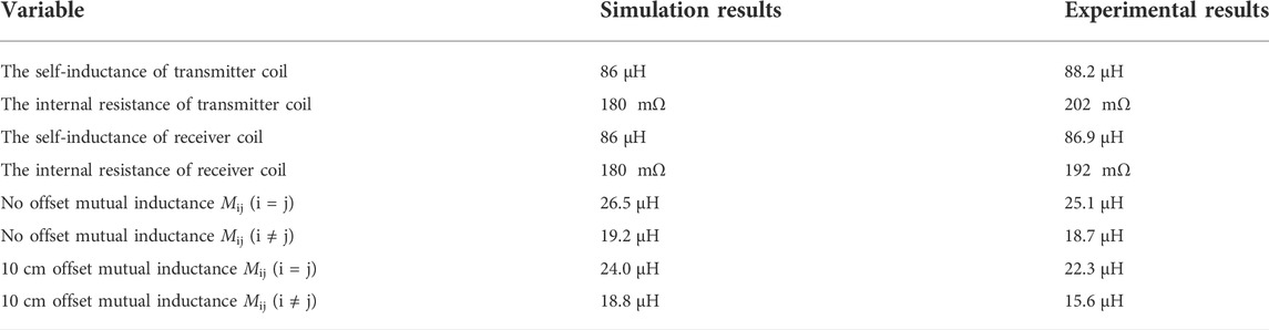
TABLE 2. The comparison between the experimental results and the simulation results.
3.2 Experimental verification of the multi-transmitter-multi-receiver wireless power transfer system
In order to verify the proposed transmitter current synchronization strategy, two experiments were carried out with different parameter setups.
First, when no control strategy is utilized, the currents in each coil cannot be completely consistent, and there are differences in the phase and amplitude of the currents. In addition, the current of one coil will be larger, so the losses on this coil are also higher than others.
Afterward, when the system adopts the control strategies, the current of each transmitter coil can be consistent in both phase and amplitude. At this time, the reactive component of each coil current corresponding to the combined current is substantially zero. In addition, the capacitance compensation method effectively decoupled the coils, so as to ensure each inverter maximizes its function.
Two experiments are carried out to validate the aforementioned analysis. First, the control board provides the same drive signal for three different inverters as shown in Figure 11A, which is an alternating square wave of 85 kHz. When the inverter output voltage is adjusted to 300 V, the waveform of the steady-state current of each coil is shown in Channel 2, Channel 3, and Channel 4 in Figure 11A. As can be seen from the waveform, the current flowing through each coil are different in phase and amplitude. Secondly, we add the proposed phase synchronization strategy to the control system. The experimental result under the same input voltage is shown in Figure 11B. With the control strategy proposed in this study, both the current phase and amplitude of each transmitter coil can be kept stable. The reactive component of each coil current is approximately zero, and the active component is basically identical. In addition, it is shown that the capacitor compensation measures adopted at the transmitter play a good role in cross-decoupling.
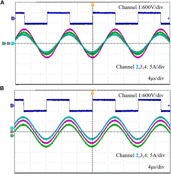
FIGURE 11. Coil current and output voltage waveform when output power is 3 kW. (A) Without a control strategy. (B) With control strategy. The signal of channel 1 represents the output voltage of the inverter from three transmitters, and the signals of channels 2, 3, and 4 represent the steady-state currents of the three transmitter coils respectively.
The overall output power of the system is 3.072 kW, and the overall system efficiency is 92.49%. Compared with the system without the proposed strategy, the system efficiency is improved by nearly 27.7%. Finally, several tests were carried out with different output power, and the experimental results are shown in Figure 12. To summarize, during the full power range, the efficiency can be improved with the proposed strategy, and the active and reactive current decomposition methods are effective.
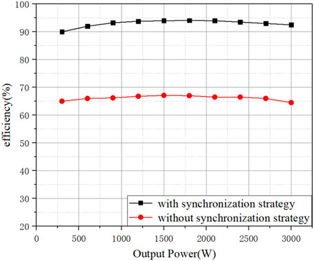
FIGURE 12. The system efficiency at different output powers.
Furthermore, in order to verify the anti-offset performance of the system, corresponding experiments were carried out. The experimental results of the MTMR WPT experimental system are compared with the experimental results of the STSR WPT system in the offset situation, and the results are shown in Figure 13. With the same coil distance and system power level, the transmission efficiency under different horizontal offset conditions is measured. It is obvious that the MTMR WPT system outperforms the STSR WPT system in anti-offset capability. When there is no offset, the efficiency of both systems can achieve 90% or higher results. However, with the increase in the offset distance, the drop rate of the STSR WPT system was significantly faster than the MTMR WPT system. When the offset distance is 40cm, the efficiency of the MTMR WPT system is about 1.45 times of the STSR WPT system. In a word, compared with the STSR WPT system, the proposed MTMR WPT system perform much better in offset situation.
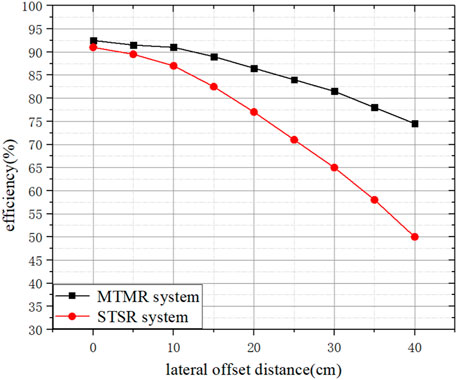
FIGURE 13. Efficiency comparison of MTMR WPT system and STSR WPT system under different offsets.
In order to present the novelty of this study more comprehensively, a Table of comparison between conducted related works in literature is added to the study. Table 3 shows the comparison of experimental results between the multi-coil WPT system in recent years in the existing literature and the system designed in this study. As can be summarized from Table 3, low power WPT systems (usually <100 W) have higher degrees of freedom in design, which come in a variety of geometries and some geometries (e.g., cylindrical, spherical, etc.) have good anti-offset performance. However, in the scenario of EV charging, the shape of the coils is limited by the vehicle chassis. Without particular anti-offset design consideration, the wireless charging efficiency will drop significantly when misalignment happens. The coupling structure proposed in this study proves to have the much better anti-offset capability while maintaining high power output capability.
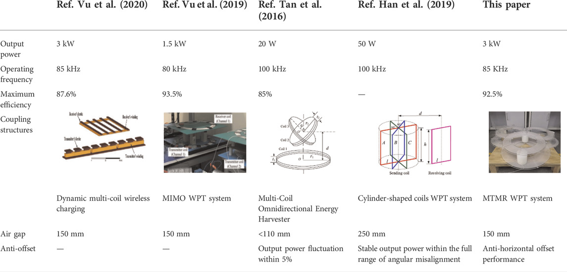
TABLE 3. Comparison of experimental results between the multi-coil WPT system in recent years from references and the system designed in this study.
4 Conclusion
As the anti-offset performance of the existing WPT system for EVs is always limited due to its uneven magnetic field distribution. In this study, a novel multi-transmitter-multi-receiver (MTMR) WPT system based on modular inverters with coils is proposed. In order to improve the transmission efficiency, the multiple transmitter coils are decoupled through the addition of compensation capacitors. Afterward, the PSO optimization algorithm was utilized to optimize the coil parameters. Then, a current synchronization control strategy of multiple transmitter coils is proposed to reduce the unbalanced current in the system. Finally, the experimental results show the efficiency of the MTMR WPT system is about 1.45 times of the STSR WPT system when the offset distance is 40 cm. The proposed MTMR system proves to have much better anti-offset capability while maintaining high power transmission ability, which provides a promising solution for future WPT solutions for EVs.
5 Appendix
The acronyms mentioned in the text and their full names are listed in Table 4.
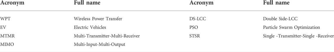
TABLE 4. The table of acronyms and their full name.
Data availability statement
The original contributions presented in the study are included in the article/Supplementary Material, further inquiries can be directed to the corresponding author.
Author contributions
JZ contributed to the conception and design of the study. JL wrote the first draft of the manuscript and contributed to the theoretical analysis. YM, JG, and AY contributed to the simulation and experimental part. All authors contributed to manuscript revision, read, and approved the submitted version.
Conflict of interest
Author JL is employed by State Grid Zhejiang Hangzhou Electric Power Co., Ltd. YM was employed by Zhejiang Dayou Group Co., Ltd.
The remaining authors declare that the research was conducted in the absence of any commercial or financial relationships that could be construed as a potential conflict of interest.
Publisher’s note
All claims expressed in this article are solely those of the authors and do not necessarily represent those of their affiliated organizations, or those of the publisher, the editors, and the reviewers. Any product that may be evaluated in this article, or claim that may be made by its manufacturer, is not guaranteed or endorsed by the publisher.
References
Bandyopadhyay, S., Venugopal, P., Dong, J., and Bauer, P. (2019). Comparison of magnetic couplers for IPT-based EV charging using multi-objective optimization. IEEE Trans. Veh. Technol. 68 (6), 5416–5429. doi:10.1109/tvt.2019.2909566
Budhia, M., Covic, G. A., and Boys, J. T. (2011). Design and optimization of circular magnetic structures for lumped inductive power transfer systems. IEEE Trans. Power Electron. 26 (11), 3096–3108. doi:10.1109/tpel.2011.2143730
Cheng, C., Zhou, Z., Li, W., Zhu, C., Deng, Z., and Mi, C. C. (2019). A multi-load wireless power transfer system with series-parallel-series compensation. IEEE Trans. Power Electron. 34 (8), 7126–7130. doi:10.1109/tpel.2019.2895598
Clerc, M., and Kennedy, J. (2002). The particle swarm - explosion, stability, and convergence in a multidimensional complex space. IEEE Trans. Evol. Comput. 6 (1), 58–73. doi:10.1109/4235.985692
Deflorio, F. P., Castello, L., Pinna, I., and Guglielmi, P. (2015). ’Charge while driving’ for electric vehicles: road traffic modeling and energy assessment. J. Mod. Power Syst. Clean. Energy 3 (2), 277–288. doi:10.1007/s40565-015-0109-z
Elliott, G. A. J., Raabe, S., Covic, G. A., and Boys, J. T. (2010). Multiphase pickups for large lateral tolerance contactless power-transfer systems. IEEE Trans. Ind. Electron. 57 (5), 1590–1598. doi:10.1109/tie.2009.2031184
Han, H., Mao, Z., Zhu, Q., Su, M., and Hu, A. P. (2019). A 3D wireless charging cylinder with stable rotating magnetic field for multi-load application. IEEE Access 7, 35981–35997. doi:10.1109/access.2019.2903831
Hasanzadeh, S., and Vaez-Zadeh, S. (2015). A review of contactless electrical power transfer: applications, challenges and future trends. Automatika 56 (3), 367–378. doi:10.7305/automatika.2015.12.727
Hasanzadeh, S., and Vaez-Zadeh, S. (2013). Efficiency analysis of contactless electrical power transmission systems. Energy Convers. Manag. 65, 487–496. doi:10.1016/j.enconman.2012.07.007
Hasanzadeh, S., Vaez-Zadeh, S., and Isfahani, A. H. (2012). Optimization of a contactless power transfer system for electric vehicles. IEEE Trans. Veh. Technol. 61 (8), 3566–3573. doi:10.1109/tvt.2012.2209464
Kim, S., Covic, G. A., and Boys, J. T. (2017). Tripolar pad for inductive power transfer systems for EV charging. IEEE Trans. Power Electron. 32 (7), 5045–5057. doi:10.1109/tpel.2016.2606893
Lee, H., Boo, S., Kim, G., and Lee, B. (2020). Optimization of excitation magnitudes and phases for maximum efficiencies in a MISO wireless power transfer system. J. Electromagn. Eng. Sci. 20, 16–22. doi:10.26866/jees.2020.20.1.16
Lee, H., and Lee, B. (2020). “Investigation of MIMO wireless power transfer efficiency in optimization techniques,” in 2020 IEEE international symposium on antennas and propagation and north american radio science meeting, Montreal, QC, Canada, 05-10 July 2020, 1417–1418.
Li, Y., Zhao, J., Yang, Q., Liu, L., Ma, J., and Zhang, X. (2019). A novel coil with high misalignment tolerance for wireless power transfer. IEEE Trans. Magn. 55 (6), 2800904. doi:10.1109/tmag.2019.2904086
Li, H., Liu, Y., Zhou, K., He, Z., Li, W., and Mai, R. (2019). Uniform power IPT system with three-phase transmitter and bipolar receiver for dynamic charging. IEEE Trans. Power Electron. 34 (3), 2013–2017. doi:10.1109/tpel.2018.2864781
Ming, X., Qingxin, Y., Pengcheng, Z., Jianwu, G., Yang, L., and Xian, Z. (2021). Application status and key issues of wireless power transmission technology. Trans. China Electrotech. Soc. 36 (8), 1547–1568. doi:10.19595/j.cnki.1000-6753.tces.200059
Musavi, F., and Eberle, W. (2014). Overview of wireless power transfer technologies for electric vehicle battery charging. IET Power Electron. 7 (1), 60–66. doi:10.1049/iet-pel.2013.0047
Pries, J., Galigekere, V. P. N., Onar, O. C., and Su, G. (2020). A 50-kW three-phase wireless power transfer system using bipolar windings and series resonant networks for rotating magnetic fields. IEEE Trans. Power Electron. 35 (5), 4500–4517. doi:10.1109/tpel.2019.2942065
Riehl, P. S., Satyamoorthy, A., Akram, H., Yen, Y. C., Yang, J. C., Juan, B., et al. (2015). Wireless power systems for mobile devices supporting inductive and resonant operating modes. IEEE Trans. Microw. Theory Tech. 63 (3), 780–790. doi:10.1109/tmtt.2015.2398413
Seo, D. -W. (2019). Comparative analysis of two- and three-coil WPT systems based on transmission efficiency. IEEE Access 7, 151962–151970. doi:10.1109/access.2019.2947093
Shen, H., Tan, P., Song, B., Gao, X., and Zhang, B. (2022). Receiver position estimation method for multitransmitter WPT system based on machine learning. IEEE Trans. Ind. Appl. 58 (1), 1231–1241. doi:10.1109/tia.2021.3103489
Tan, P., Cao, S., and Gao, X. (2016). “Adjustable coupler for inductive contactless power transfer system to improve lateral misalignment tolerance,” in IEEE power electronics and motion control conference, Hefei, China, 22-26 May 2016, 2423–2426.
Vu, V., Dahidah, M., Pickert, V., and Phan, V. -T. (2020). A high-power multiphase wireless dynamic charging system with low output power pulsation for electric vehicles. IEEE J. Emerg. Sel. Top. Power Electron. 8 (4), 3592–3608. doi:10.1109/jestpe.2019.2932302
Vu, V., Luqman, B. M. K., Jasper, T., Volker, P., Mohamed, D., Thillainathan, L., et al. (2017). “A multi-output capacitive charger for electric vehicles,” in 2017 IEEE 26th international symposium on industrial electronics (ISIE), Edinburgh, UK, 19-21 June 2017, 565–569.
Vu, V., Phan, V., Dahidah, M., and Pickert, V. (2019). Multiple output inductive charger for electric vehicles. IEEE Trans. Power Electron. 34 (8), 7350–7368. doi:10.1109/tpel.2018.2882945
Wu, H. H., Covic, G. A., Boys, J. T., and Robertson, D. J. (2010). A series-tuned inductive-power-transfer pickup with a controllable AC-voltage output. IEEE Trans. Power Electron. 20 (1), 98–109. doi:10.1109/tpel.2010.2052069
Zhang, X., Qi, H., Zhang, X., and Han, L. (2021). Spectral efficiency improvement and power control optimization of massive MIMO networks. IEEE Access 9, 11523–11532. doi:10.1109/access.2021.3051170
Zhang, Z., Pang, H., Georgiadi, A., and Cecati, C. (2019). Wireless power transfer-an overview. IEEE Trans. Ind. Electron. 66 (2), 1044–1058. doi:10.1109/tie.2018.2835378
Zhou, J., Yao, P., Guo, K., Cao, P., Zhang, Y., and Ma, H. (2020). A heterogeneous inductive power transfer system for electric vehicles with spontaneous constant current and constant voltage output features. Electronics 9 (11), 1978. doi:10.3390/electronics9111978
Zhou, J., Guo, K., Chen, Z., Sun, H., and Hu, S. (2020). Design considerations for contact-less underwater power delivery: a systematic review and critical analysis. Wirel. Pow. Transf. 7 (1), 76–85. doi:10.1017/wpt.2020.3
Keywords: wireless power transfer, multi transmit-multi receive, particle swarm optimization, misalignment, efficiency
Citation: Liu J, Min Y, Gao J, Yang A and Zhou J (2022) Design and optimization of a modular wireless power system based on multiple transmitters and multiple receivers architecture. Front. Energy Res. 10:896575. doi: 10.3389/fenrg.2022.896575
Received: 15 March 2022; Accepted: 27 July 2022;
Published: 02 September 2022.
Edited by:
Zhikang Shuai, Hunan University, ChinaReviewed by:
Mohamed Salem, Universiti Sains Malaysia (USM), MalaysiaSaeed Hasanzadeh, Qom University of Technology, Iran
Copyright © 2022 Liu, Min, Gao, Yang and Zhou. This is an open-access article distributed under the terms of the Creative Commons Attribution License (CC BY). The use, distribution or reproduction in other forums is permitted, provided the original author(s) and the copyright owner(s) are credited and that the original publication in this journal is cited, in accordance with accepted academic practice. No use, distribution or reproduction is permitted which does not comply with these terms.
*Correspondence: Jing Zhou, amluZ3pob3VAemp1LmVkdS5jbg==