 Buxin She
 Yuqing Dong
 Yilu Liu
94% of researchers rate our articles as excellent or good
Learn more about the work of our research integrity team to safeguard the quality of each article we publish.
Find out more
ORIGINAL RESEARCH article
Front. Energy Res., 27 April 2022
Sec. Smart Grids
Volume 10 - 2022 | https://doi.org/10.3389/fenrg.2022.895163
This article is part of the Research TopicIntelligent Operation and Control in Next Generation Urban Power GridView all 14 articles
Due to the rapid development of economies, large urban cities consume an increasing amount of energy and have a higher requirement for power quality. Voltage source converter based high voltage direct current (VSC-HVDC) is a promising device to transmit clean power from remote regions to urban power systems, while also providing wide area damping control (WADC) for frequency stabilization. However, the time-delay naturally existing in the VSC-HVDC system may degrade the performance of WADC and even result in instability. To address this issue, this paper develops a time-delay correction control strategy for VSC-HVDC damping control in urban power grids. First, a small signal model of WADC is built to analyze the negative impacts of time delay. Then, a data-driven approach is proposed to compensate for the inherent time delay in VSC-HVDC damping control. The extensive training data will be generated under various disturbances. After offline training, the long short-term memory network (LSTM) can be implemented online to predict the actual frequency deviation based on real-time measurements. Finally, the proposed method is validated through MATLAB-Simulink in a two-area four-machine system. The results indicate that the data-driven compensation has a strong generalization ability for random delay time constants and can improve the performance of WADC significantly.
Urbanization has witnessed the development of modern civilization (Jiang et al., 2019). Urban power grids are accommodating more people and consuming more energy than ever before (Xiao et al., 2022). With distributed energies and loads from distant areas (Pan et al., 2021; Sun et al., 2022; Yang et al., 2022), VSC-HVDC has been widely used to transmit clean energy from remote regions to urban power (Fu et al., 2021; Sun et al., 2021b; Xiao et al., 2021). On the other hand, the increasing uncertainty of distributed energy resources (Li S. et al., 2021; Zhang J. et al., 2022), extreme weather, and flexible loads like electrical vehicles pose great challenges to the frequency regulation of urban power grids (Xiong et al., 2021). With the interconnection of different regions of power grids, the inter-area low-frequency oscillations have also become a serious issue that threatens the system’s stability (Baltas et al., 2021).
Wide area damping control (WADC) provides a promising approach to mitigate the oscillations of frequency and thus improve the stability of urban power grids (Li and Chen, 2018). However, in WADC, the control signals measured by phasor measurement unit (PMU) are transmitted from a distant region through communication channels, which may bring an unavoidable time delay (Musleh et al., 2018). Such kind of delay can vary from tens to hundreds of milliseconds (He et al., 2009), depending on different communication distances, protocols, and measuring devices. Some research have reported that the existing time delay, even with a small value, will result in the loss of WADC control and power system instability (Xu et al., 2020). Considering the fast power controllability of VSC-HVDC (Sun et al., 2021a; Dong et al., 2021), the time delay in the control signal may bring a more destabilizing influence than other devices.
Some control strategies have been proposed to deal with the time delay in WADC. One of the conventional methods focuses on the offline parameter optimization of WADC, based on linear matrix inequality theory (LMI) (Chang et al., 2006; Li et al., 2010), Smith Predictor (Chaudhuri et al., 2004) and robust control strategies (Wang et al., 2010), which usually relies on known models and uses fixed parameters. To adapt to the varying conditions of the system operation, some adaptive control strategies are put forward to compensate the time delay more realistically (Cheng et al., 2014) (Zhu et al., 2016). The main idea of the adaptive control is to schedule the control gains and the phase compensation parameters according to the online identification of the system model and oscillation modes. Nevertheless, the model estimation requires characteristic extraction from continuous ambient data injection, which may be influenced by system background noise and is not necessarily accurate and instantaneous.
Recently, the rapid development of artificial intelligence has created the potential for time delay compensation with neural networks. Among the various neural networks, the long short-term memory network (LSTM) is a kind of modern recurrent neural network that is designed for handling time series data (Xu et al., 2021). It has been successfully employed in power systems for islanding detection (Abdelsalam et al., 2020), load and generation forecast (Liu et al., 2020)-(Alavi et al., 2021), fast event identification (Li Z. et al., 2021), and measurements prediction (Wang et al., 2021). One common feature of these studies is that they made the best use of the time-series properties of power system data. Actually, the delayed PMU measurements are awesome time series data that can help predict the real time frequency deviation for WADC. Apart from LSTM, multilayer perception (MLP) and convolutional network (CNN) may also be used to predict delayed signals. However, MLP suffers from the computational burden when dealing with time-series data, and CNN cannot preserve the long-term information and skip the short-term input at the same time. Hence, this paper tries to integrate LSTM into the time delay compensation of urban VSC-HVDC systems. Compared with the existing literature, this paper has the following contributions.
• Formulated a small signal model of WADC with time delay and mathematically proved that the uncorrected PUM signals can result in the instability of the urban power grids.
• Proposed a data-driven delay compensation approach for WADC, leveraging the modern recurrent neural network LSTM. A well-trained LSTM was implemented online for time delay compensation after thorough offline training under various disturbances.
• Verified the proposed method through numerical simulation. Results showed that the LSTM-based compensation method has strong generalization ability. It can adapt to random delay time in real system even though the delay time constants were not included in the training dataset.
The rest of this paper is organized as follows. Model-Based Analysis on Time Delay of Wide Area Damping Control Section builds up the small signal model of WADC with time delay and analyzes the negative impacts based on eigenvalue analysis. In Data-Driven Delay Compensation With LSTM Section, a data-driven delay compensation approach is developed using LSTM. Case Study Section validates the proposed method in a two-area four machine system with a comprehensive test. Finally, conclusions are drawn in Conclusion Section.
With the large-scale application of PMU measurement and power electronics technology, VSC-HVDC has been widely used in the field of WADC. The typical framework is shown in Figure 1. According to the frequency data collected by the PMUs in different regions, the WADC adjusts the DC power reference value to suppress the inter-area low-frequency oscillations.
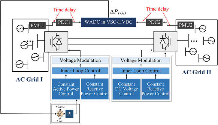
FIGURE 1. System diagram of VSC-HVDC.
In Figure 1, fPMU1, fPMU2 are the real-time frequencies collected by PMU1 and PMU2, respectively.
• The PMU configured in the AC grid measures the three-phase bus voltage and calculates the bus frequency.
• After data packaging, the frequency data from different PMUs is transmitted to the phase data concentrators (PDCs). During the transmission process, a special communication protocol, such as IEEE C37.118, is used to ensure the transmission security and accuracy.
• The PDC then unpacks the frequency data and sends it to the WADC of the VSC-HVDC.
• Figure 2 illustrates the block diagram of the WADC. It consists of a washout block, a band-pass filter, two phase compensation blocks, and a gain block. The input of the controller is the difference between the frequencies collected by the two PMUs; while the output of the controller is the active power reference value PPOD. The time constant Tω of the washout filter is chosen as 10s. In the band-pass filter, ωn is the system oscillation frequency, and Q is the quality factor, which is usually set as 1. For active power modulation, the time constant in the compensation block can be considered as the same value, i.e., T1s = T2s; kPOD is the controller gain. PPOD_max and PPOD_min are the output limits of the WADC.
• PPOD will then be added as an auxiliary signal to the Pref of the VSC-HVDC outer loop control to modulate the DC active power.
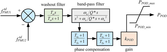
FIGURE 2. Control diagram of WADC.
In the practical system operation, the time delay exists from PMU to PDC, and then to the WADC.
In order to quantitatively analyze the influence of the time delay in VSC-HVDC system, a small signal model of VSC-HVDC with WADC considering the time delay has been established. In the test system, two generators are modeled to represent the two distant areas. A VSC station is connected to the two areas through transmission lines. The control strategy of the VSC-HVDC includes the WADC, outer loop control, inner loop control, and phase-locked loop (PLL).
For the generators in two areas, the rotor motion equations are shown in (Eq. 1).
where δ1,2 and ωg1,2 are the rotor phase and rotor angular velocity of the two generators. TJ1,2 is the inertia time constant; D1,2 is the damping coefficient; Tm1,2 is the mechanical torque; while Te1,2 is the electrical torque.
In the test system, the PMUs collect the frequencies at the ports of the two generators, so it can be considered that fPMU1, fPMU2 are consistent with the corresponding generator frequencies, as shown in (Eq. 2).
After the time delay, the difference between
where ferror = fPMU1- fPMU2.
The state space equation of the Pade approximation can be transformed from (Eq. 3).
Eq. 4 introduces four state variables zp = [z1 z2 z3 z4]T; the input variable up = ferror; the output variable is yp =
The delayed frequency signal can then be expressed as (5):
where
Transforming it into the state space form:
Combining with the outer loop control, inner loop control, and PLL function of the VSC, the small signal model of the complete test system can be obtained after linearization, as shown in (Eq. 9).
where A is a 21 × 21 state matrix; B is a 21 × 2 input matrix.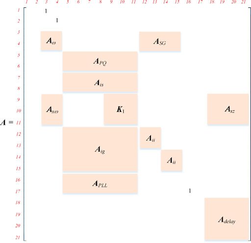
With the established small signal state space model, eigenvalue analysis can be conducted to investigate the stability of the system. As shown in Figure 3, the dominant eigenvalue of A is presented with time delay Td varying from 200 to 500 ms. The other parameters of the test system remain constant.
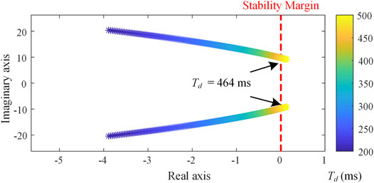
FIGURE 3. Dominant eigenvalue of A.
In Figure 3, with the increase of Td, the dominant eigenvalue gradually moves towards the positive direction of the real-axis. When Td is greater than 464 ms, the eigenvalue will pass through the imaginary-axis and reach the right half plane of the coordinate axis, indicating that the system becomes unstable.
It can be concluded that: the stability margin of the system is reduced with the increase of the time delay, and even instability may occur. Therefore, in a VSC-HVDC system with WADC strategy, the time delay issue needs to be carefully resolved to guarantee the system stability.
This section firstly gives an overview of LSTM and then employs it on time-delay compensation for WADC.
To improve the numerical instability of RNNs, several tricks such as new structure design are developed and implemented in the sophisticated sequence models. LSTM is one of the promising models that solves the problem of preserving the long-term information and skipping short-term input. Figure 4 shows the basic cell of LSTM. Apart from the typical input and output, the cell also includes a few gates recurrent units (GRUs), memory, candidate memory, and hidden state. They are illustrated as follows (Zhang A. et al., 2022).
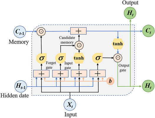
FIGURE 4. Basic cell of LSTM.
There are three gate recurrent units utilized in LSTM: 1). input gate It is to decide whether to read data into the cell; 2). output gate Ot is responsible for reading out the entries from the cell; and 3). forget gate Ft is designed for resetting the content of the cell. The hidden states and the input data are fed to the three units and processed by fully-connected layers with sigmoid activation functions. The output of the three GRUs is calculated as follows.
where Wxi, Wxf, Wxo, Wni, Wnf, and Wno are weight parameters, and bi, bf, and bi are bias parameters.
LSTM can choose to remember or forget the information from the last time slot, leveraging the input gate and forget gate. First, candidate memory is generated using a tanh function as activation function.
where
where ⊙ is the Hadamard (elementwise) robust operator. The combination of past cell memory and candidate memory enables the pass of cell memory and thus alleviates the vanishing gradient problem.
As shown in (Eq. 13), hidden state Ht is calculated by integrating the current memory into the last hidden state. Ht belongs to [-1, 1] because it is processed by tanh before passed to the next cell.
With the special designs above, LSTM can finally capture the dependencies from historical data and predict the future value accurately.
This subsection dives into the implementation of LSTM for delay compensation of WADC.
Figure 5 shows the fundamental idea of the time delay compensation. PMU1 and PMU2 are implemented locally in two urban power grids to measure voltage and frequency. The delay usually happens on the signal transmission from PMU to damping control center. Typically, the delay is within the range of [10 ms, 500 ms], and the delay time constant varies depending on the distance of PUM to damping control center and the types of disturbances. An LSTM is employed locally in the damping control center to correct the sampled data before passing the delayed signals to controllers. In this way, the damping controller can function effectively without worrying about the negative impacts of communication time delay.

FIGURE 5. Diagram of employing LSTM for time-delay compensation.
LSTM predicts the real time frequency of Area I and Area II based on the delayed data from PMU1 and PMU2. For each time slot, the input data Xt = [fPMU1t, fPMU2t, ∆fPMUt, VPMU1t, VPMU2t]. The number of hidden units is denoted by N, representing how far LSTM looks back when correcting the time delay. Then, the input data are normalized before being fed into the LSTM cell. Finally, LSTM outputs the real time f1t, f2t, and ∆ft.
Before feeding the predicted frequency error to damping controller, data fusion is utilized to increase the robustness of the time delay compensation. The final frequency error is calculated by integrating the predicted frequency into the predicted error as follows.
where α is a hyperparameter that controls the fusion rate. The data fusion can smooth the prediction error and increase the stability of the data-driven approach.
The strategy of offline training and online implementation is used in this paper. As shown in Figure 6, the offline training is three-fold: training scenario generation, simulation and data sampling, and LSTM training, while online implementation includes LSTM prediction, numerical security check, and data passing. They are illustrated in detail in the following subsections.
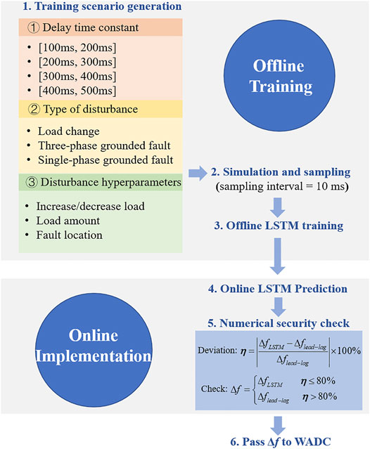
FIGURE 6. Diagram of offline training and online implementation.
The training data is generated under various disturbances. With the random combination of the three key elements that determine a disturbance, i.e., delay time constant, type of disturbance, and disturbance hyperparameters, the training data set can cover common disturbances in urban power systems. For each generated disturbance, perform numerical simulation in MATLAB-Simulink and sample the input data with time delay and the output data without time delay. The time interval of sampling is set as 10 ms, which is identical to the PMU sampling rate in reality. Then, all the training data are packaged for LSTM training.
After extensive training, the well-trained LSTM is ready for online implantation. As shown in Figure 5, LSTM network predicts the real time frequency error between the two urban power systems based on the delayed PMU data. To guarantee the security of implementing unexplainable neural network, a numerical security check is performed before passing the predictions to damping controller. The online prediction of LSTM is compared with that of the model-based lead-lag time delay compensator. If the prediction of LSTM deviates less than 80% from the lead-lag controller, the prediction is passed to damping controller. Otherwise, the conventional predictor will be used. The security check is designed to prevent the numerical instability of neural network prediction. Due to the non-interpretability of LSTM, we cannot guarantee that LSTM always predicts the error within an acceptable range. Hence, the model-based lead-lag module is used to generate the interpretable correction signals that are certainly secure. Eqs 15, 16 show the security check process, which enhances the stability and reliability of the data-driven compensation.
This section validates the proposed time-delay compensation approach in a two-area four-machine system.
As shown in Figure 7, both Area I and Area II have two synchronous generators supplying local loads, and they are connected through AC transmission lines and VSC-HVDC. The AC transition is responsible for the transmission of active power, while the VSC-HVDC performs wide area damping control based on PMU measurements. PMU1 and PMU2 are equipped at the terminal of G1 and G3, respectively.
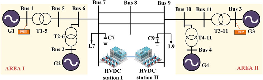
FIGURE 7. Diagram of the two-area four-machine system. Scenario I: Partial Dataset Training.
To better validate the generalization of the data-driven method, the offline training data is divided into several groups based on delay time constant, type of disturbance, and disturbance hyperparameters. In Scenario I, LSTM is trained on a dataset of partial disturbances, while in Scenario II, LSTM is trained on a dataset of all kinds of disturbances.
In Scenario I, the training dataset is generated on the disturbance of load change with delay time constant belonging to (100 ms, 200 ms) and (300 ms, 400 ms). Then, conduct LSTM training using the hyperparameters listed in Table 1, and the training results are presented in Figure 8. After 250 episodes, the LSTM’s prediction root mean square error (RMSE) and training loss are both near zero, indicating that the LSTM has a high forecast accuracy on the training dataset.
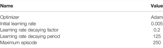
TABLE 1. Training hyperparameter of LSTM.
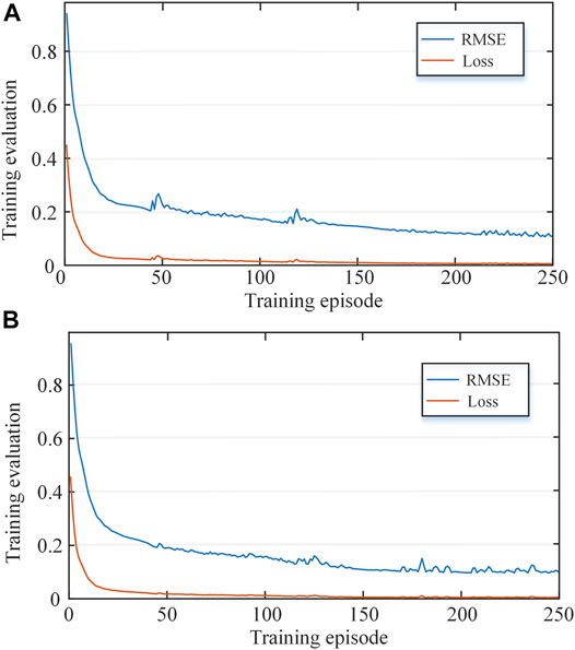
FIGURE 8. Offline training error. (A) Scenario I. (B) Scenario II.
Assume the fusion rate α = 0.5, the well-trained LSTM is implemented online and tested under the conditions in Table 2. The validation results are plotted in Figure 9A, based on which we have the following observations.
• Time delay degrades the performance of the WADC. The oscillation becomes severe when directly utilizing the delayed signal from PMU.
• In No.1 and No. 2 validation conditions, although the delay time constant 250 ms doesn’t belong to the training dataset, LSTM can still correct the delayed frequency accurately.
• There is a minor oscillation around 4 Hz in No.1 validation condition. The oscillation is outside WADC’s target suppression mode, so it is not suppressed considerably.
• In No. 3 and No. 4 validation conditions, LSTM doesn’t compensate for the delayed signals well because neither of the three key elements that determine a disturbance belongs to the training dataset. However, the performance of WADC is somewhat improved with the compensation of LSTM.

TABLE 2. Validation condition.
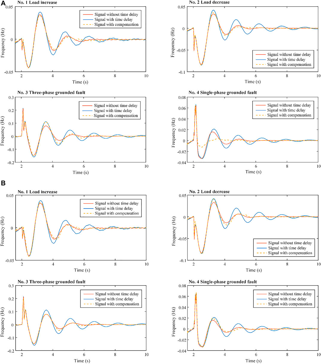
FIGURE 9. Online validation results. (A) Scenario I. (B) Scenario II.
To validate the overall performance of LSTM, the dataset of three kinds of disturbance is used for offline training in Scenario II. The delay time constant and the disturbance hyperparameters are identical to those in Scenario II. Using the training hyperparameters in Table 1, the LSTM’s prediction RMSE and training loss converge to 0 after training for 250 episodes. Figure 9B shows the training error, which suggests that LSTM can predict the un-delayed signals accurately.
Assume the fusion rate α = 0.5, the well-trained LSTM is implemented online and tested under the conditions in Table 2.
Figure 9 shows the dynamic frequency with and without the compensation. We can see that in the four validation conditions, although the test delay time constant 250 ms doesn’t belong to the training dataset, LSTM can predict the error of delay accurately. The performance of WADC’s has improved significantly. Figure 10 further plots the normalized online prediction error, which can be expressed in (Eq. 17).
where NOPE is the “normalized online prediction error”; i represents the respective case in each scenario.

FIGURE 10. Normalized online prediction error of LSTM in Scenario I and Scenario II.
The NOPE of three-phase grounded fault and single-phase grounded fault in Scenario I is much less than that in Scenario II, indicating that LSTM has insufficient generalization ability for the type of disturbance. Hence, the training dataset should cover all types of disturbance as much as possible in practical application.
In general, a well-trained LSTM can provide accurate correction signals for WADC. It has strong generalization ability for delay time constant, which is beneficial to its employment in real systems. With the delay compensator, WADC can address the random time delay and improve its damping performance significantly.
The time delay in WADC can degrade the performance of damping controllers and even results in instability. The root cause is revealed through small signal modeling and eigenvalue analysis in this paper. To address this issue, this paper further proposed a data-driven approach to compensate for the delayed PMU signals, which leverages the modern recurrent neural network LSTM. The compensation procedure includes offline training and online implantation. Through partial dataset training and complete dataset training in a two-area four-machine system, it is verified that LSTM corrects the delayed frequency accurately. LSTM has strong generalization ability for delay time constant and can deal with the random time delay caused by commination and disturbances in urban power grids. After employing the delay correction approach, the damping performance of WADC is improved significantly.
One potential weakness of our work is that LSTM needs as many training data that cover all kinds of disturbances as possible. Our future work may include developing a more efficient training method with less training data, improving the generalization ability of LSTM to handle new disturbances, integrating the topology change into data generation, and validating the data-driven approach in a hardware-in-the-loop system.
The original contributions presented in the study are included in the article/Supplementary Material, further inquiries can be directed to the corresponding author.
BS contributed to conception and design of the study. YD generated the database and implemented simulation. YL provided guidance to the study. BS and YD wrote the draft of the manuscript. All authors contributed to manuscript revision, read, and approved the submitted version.
The authors declare that the research was conducted in the absence of any commercial or financial relationships that could be construed as a potential conflict of interest.
All claims expressed in this article are solely those of the authors and do not necessarily represent those of their affiliated organizations, or those of the publisher, the editors and the reviewers. Any product that may be evaluated in this article, or claim that may be made by its manufacturer, is not guaranteed or endorsed by the publisher.
Abdelsalam, A. A., Salem, A. A., Oda, E. S., and Eldesouky, A. A. (2020). Islanding Detection of Microgrid Incorporating Inverter Based DGs Using Long Short-Term Memory Network. IEEE Access 8, 106471–106486. doi:10.1109/ACCESS.2020.3000872
Alavi, S. A., Mehran, K., Vahidinasab, V., and Catalao, J. P. S. (2021). Forecast-Based Consensus Control for DC Microgrids Using Distributed Long Short-Term Memory Deep Learning Models. IEEE Trans. Smart Grid 12, 3718–3730. doi:10.1109/TSG.2021.3070959
Baltas, G. N., Lai, N. B., Tarraso, A., Marin, L., Blaabjerg, F., and Rodriguez, P. (2021). AI-based Damping of Electromechanical Oscillations by Using Grid-Connected Converter. Front. Energ. Res. 9, 598436. doi:10.3389/fenrg.2021.598436
Chang, Y., Chen, H., Cheng, G. H., and Xie, J. (2006). “Design of HVDC Supplementary Controller Accommodating Time Delay of the WAMS Signal in Multi-Machine System,” in IEEE Power Engineering Society General Meeting. Montreal, QC, Canada: IEEE, 7. doi:10.1109/PES.2006.1709071
Chaudhuri, B., Majumder, R., and Pal, B. C. (2004). Wide-area Measurement-Based Stabilizing Control of Power System Considering Signal Transmission Delay. IEEE Trans. Power Syst. 19, 1971–1979. doi:10.1109/TPWRS.2004.835669
Cheng, L., Chen, G., Gao, W., Zhang, F., and Li, G. (2014). Adaptive Time Delay Compensator (ATDC) Design for Wide-Area Power System Stabilizer. IEEE Trans. Smart Grid 5, 2957–2966. doi:10.1109/TSG.2014.2347401
Dong, Y., Ma, J., Wang, S., Liu, T., Chen, X., and Huang, H. (2021). An Accurate Small Signal Dynamic Model for LCC-HVDC. IEEE Trans. Appl. Supercond. 31, 1–6. doi:10.1109/TASC.2021.3107804
Fu, Y., Hu, C.-H., and Yang, D.-X. (2021). Conservative or Aggressive? the Dynamic Adjustment of the Feed-In Tariff Policy for Photovoltaic Power Generation in China. Front. Energ. Res. 9, 672920. doi:10.3389/fenrg.2021.672920
He, J., Wu, X., Li, P., Lu, C., and Wu, J. (2009). Design and experiment of Wide Area HVDC Supplementary Damping Controller Considering Time Delay in China Southern Power Grid. IET Generation, Transm. Distribution 3, 17–25. doi:10.1049/iet-gtd:20080129
Jiang, X., Xiao, J., She, B., and Zu, G. (2019). Locating and Sizing of Partition Flexible Interconnection Converter Station in Large Urban Power Grids. IET Generation, Transm. & Distribution 13, 4830–4841. doi:10.1049/iet-gtd.2018.6871
Li, M., and Chen, Y. (2018). A Wide-Area Dynamic Damping Controller Based on Robust H∞ Control for Wide-Area Power Systems with Random Delay and Packet Dropout. IEEE Trans. Power Syst. 33, 4026–4037. doi:10.1109/TPWRS.2017.2782792
Li, S., Hou, J., Yang, A., and Li, J. (2021). DNN-based Distributed Voltage Stability Online Monitoring Method for Large-Scale Power Grids. Front. Energ. Res. 9. doi:10.3389/fenrg.2021.625914
Li, Y., Rehtanz, C., Yang, D. C., Gorner, K., Ruberg, S., and Luo, L. F. (2010). “Wide-area Time-Delay Damping Control to Prevent Power Oscillations in HVDC/AC Interconnected Power Systems,” in 2010 International Conference on Power System Technology. Zhejiang, China: IEEE, 1–6. doi:10.1109/POWERCON.2010.5666549
Li, Z., Liu, H., Zhao, J., Bi, T., and Yang, Q. (2021). Fast Power System Event Identification Using Enhanced LSTM Network with Renewable Energy Integration. IEEE Trans. Power Syst. 36, 4492–4502. doi:10.1109/TPWRS.2021.3064250
Liu, B., Chen, J., Wang, H., and Wang, Q. (2020). Renewable Energy and Material Supply Risks: a Predictive Analysis Based on an LSTM Model. Front. Energ. Res. 8, 163. doi:10.3389/fenrg.2020.00163
Musleh, A. S., Muyeen, S. M., Al-Durra, A., Kamwa, I., Masoum, M. A. S., and Islam, S. (2018). Time-Delay Analysis of Wide-Area Voltage Control Considering Smart Grid Contingences in a Real-Time Environment. IEEE Trans. Ind. Inf. 14, 1242–1252. doi:10.1109/TII.2018.2799594
Pan, G., Hu, Q., Gu, W., Ding, S., Qiu, H., and Lu, Y. (2021). Assessment of Plum Rain's Impact on Power System Emissions in Yangtze-Huaihe River basin of China. Nat. Commun. 12, 6156. doi:10.1038/s41467-021-26358-w
Sun, K., Li, K.-J., Zhang, Z., Liang, Y., Liu, Z., and Lee, W.-J. (2022). An Integration Scheme of Renewable Energies, Hydrogen Plant, and Logistics Center in the Suburban Power Grid. IEEE Trans. Ind. Applicat. 58, 2771–2779. doi:10.1109/TIA.2021.3111842
Sun, K., Qiu, W., Yao, W., You, S., Yin, H., and Liu, Y. (2021a). Frequency Injection Based HVDC Attack-Defense Control via Squeeze-Excitation Double CNN. IEEE Trans. Power Syst. 36, 5305–5316. doi:10.1109/TPWRS.2021.3078770
Sun, K., Xiao, H., Pan, J., and Liu, Y. (2021b). VSC-HVDC Interties for Urban Power Grid Enhancement. IEEE Trans. Power Syst. 36, 4745–4753. doi:10.1109/TPWRS.2021.3067199
Wang, M., Liu, J., and Liu, J. (2010). “Delay-dependent Robust H∞ Control of Nonlinear Uncertain Time-Delay Systems,” in IEEE ICCA. Xiamen, China: IEEE, 1249–1254. doi:10.1109/ICCA.2010.5524229
Wang, Q., Bu, S., He, Z., and Dong, Z. Y. (2021). Toward the Prediction Level of Situation Awareness for Electric Power Systems Using CNN-LSTM Network. IEEE Trans. Ind. Inf. 17, 6951–6961. doi:10.1109/TII.2020.3047607
Xiao, H., Sun, K., Pan, J., Li, Y., and Liu, Y. (2021). Review of Hybrid HVDC Systems Combining Line Communicated Converter and Voltage Source Converter. Int. J. Electr. Power Energ. Syst. 129, 106713. doi:10.1016/j.ijepes.2020.106713
Xiao, J., Cai, Z., Liang, Z., and She, B. (2022). Mathematical Model and Mechanism of TSC Curve for Distribution Networks. Int. J. Electr. Power Energ. Syst. 137, 107812. doi:10.1016/j.ijepes.2021.107812
Xiong, M., Xu, X., Sun, K., and Wang, B. (2021). “Approximation of the Frequency-Amplitude Curve Using the Homotopy Analysis Method,” in 2021 IEEE Power Energy Society General Meeting (PESGM). Washington, DC, United States: IEEE, 1–5. doi:10.1109/PESGM46819.2021.9638009
Xu, L., Guo, C., Peng, Y., Yang, S., and Zhao, C. (2020). “Small Signal Model of VSC-HVDC Considering the Impact of Time Delay,” in 2020 10th International Conference on Power and Energy Systems (ICPES), 286–291. doi:10.1109/ICPES51309.2020.9349709
Xu, Y., Gao, W., Qian, F., and Li, Y. (2021). Potential Analysis of the Attention-Based LSTM Model in Ultra-short-term Forecasting of Building HVAC Energy Consumption. Front. Energ. Res. 9. doi:10.3389/fenrg.2021.730640
Yang, D., Jin, Z., Zheng, T., and Jin, E. (2022). An Adaptive Droop Control Strategy with Smooth Rotor Speed Recovery Capability for Type III Wind Turbine Generators. Int. J. Electr. Power Energ. Syst. 135, 107532. doi:10.1016/j.ijepes.2021.107532
Zhang, J., She, B., Peng, J. C.-H., and Li, F. (2022). A Distributed Consensus-Based Optimal Energy Management Approach in DC Microgrids. Int. J. Electr. Power Energ. Syst. 140, 108015. doi:10.1016/j.ijepes.2022.108015
Zhu, L., Liu, H., Pan, Z., Liu, Y., Farantatos, E., Patel, M., et al. (2016). “Adaptive Wide-Area Damping Control Using Measurement-Driven Model Considering Random Time Delay and Data Packet Loss,” in 2016 IEEE Power and Energy Society General Meeting (PESGM). Boston, MA, United States: IEEE, 1–5. doi:10.1109/PESGM.2016.7741971
Keywords: wide area damping control, HVDC, small signal modeling, time delay compensation, long short-term memory
Citation: She B, Dong Y and Liu Y (2022) Time Delay of Wide Area Damping Control in Urban Power Grid: Model-Based Analysis and Data-Driven Compensation. Front. Energy Res. 10:895163. doi: 10.3389/fenrg.2022.895163
Received: 13 March 2022; Accepted: 08 April 2022;
Published: 27 April 2022.
Edited by:
Kaiqi Sun, Shandong University, ChinaCopyright © 2022 She, Dong and Liu. This is an open-access article distributed under the terms of the Creative Commons Attribution License (CC BY). The use, distribution or reproduction in other forums is permitted, provided the original author(s) and the copyright owner(s) are credited and that the original publication in this journal is cited, in accordance with accepted academic practice. No use, distribution or reproduction is permitted which does not comply with these terms.
*Correspondence: Yuqing Dong, eWRvbmcyMkB1dGsuZWR1
Disclaimer: All claims expressed in this article are solely those of the authors and do not necessarily represent those of their affiliated organizations, or those of the publisher, the editors and the reviewers. Any product that may be evaluated in this article or claim that may be made by its manufacturer is not guaranteed or endorsed by the publisher.
Research integrity at Frontiers
Learn more about the work of our research integrity team to safeguard the quality of each article we publish.