 Zean Tao1
 Mingyi Xu
- 1College of Automotive Engineering, Hu Nan Mechanical & Electrical Polytechnic, Changsha, China
- 2College of Electrical and Information Engineering, Hunan University, Changsha, China
- 3Department of Disaster Prevention and Rescue, Hunan Vocational Institute of Safety Technology, Changsha, China
- 4Hunan Creator Information Technologies Co., Ltd., Changsha, China
Magnetic characteristics of the SRM can be monitored directly in the detection of commutation instants. However, the mutual inductance effect between the adjacent phases is prominent for the switched reluctance motor when the adjacent phases are energized simultaneously. Consequently, mutual coupling will distort the response current profile of the injection voltage phase, thereby affecting position estimation precision. In order to acquire a precise estimation and accommodate it for the SRM drive system, it is necessary to take into consideration the modifications for the sensor-less scheme. This study presents a unique rotor position estimation approach to eliminate the mutual inductance effect by using the phase current slope difference method. The sensor-less scheme is achieved by setting a low and a high threshold, and a series of voltage pulses are injected in the idle phase alternately, synchronizing with the chopping current control. Without prior knowledge of mutual inductance and any additional position sensor, a precisely estimated rotor position is achieved. A dynamic model of a 12/8 SRM model is established to evaluate its validity, and both simulation results and experimental evaluation indicate that the proposed sensor-less control can be accomplished with an adequate precision used in a variety of applications.
1 Introduction
The switched reluctance motor (SRM) is of great potential to be widely used in applications such as electric vehicles, household appliances, aerospace, and other fields because of its simple structure, strong fault-tolerant ability, and flexible control characteristic (Torkaman and Afjei, 2013; Sato et al., 2016; Chang et al., 2015; Sun et al., 2020; Mynar et al., 2020). Good performance for SRM operation depends greatly on real-time rotor position, which should be synchronous with the commutation of the phase (Bu and Xu, 2001; Khalil et al., 2005; Hudson et al., 2008; Cai and Deng, 2012; Betin et al., 2014; Cai and Deng, 2015; Cai et al., 2020; Gan et al., 2020).
However, the application of position sensors such as hall sensors and encoder increases the complexity and reduces the reliability of the system, which excludes the motor from many specific applications (Hu et al., 2015). Appropriate control parameter turn-on and turn-off is essential to the position control of the SRM drive system. Therefore, it is essential for researchers to develop a practical sensor-less position detection technique, which is a key necessity for the development of the SRM drive system.
In recent years, scholars have put forward a series of sensor-less position estimation schemes, including pulse injection method, inductance-based approach, and Artificial Intelligence, on which the rotor position depends in terms of inductance, flux linkage, or electromagnetic force, all related to rotor position (Mese and Torrey,2002; Cheok and Ertugrul,2000; Gan et al., 2016; Hu et al., 2015).
When the identified winding inductance is developed to set the commutation shift angle, based on the observed speed, winding current command, and observed inductance, the inductance model–based strategy is promoted by Gao et al. (2004), and the implementation of relationships between phase current, phase incremental inductance, and rotor position is accomplished to estimate the position for the low-speed operation, and the method is not affected by the magnetic characteristics of the SRM. When the sensor-less control with a super-high speed of 20,000 rpm is achieved by adaptively tuning the general nonlinear magnetizing model (GNMM) with minimum input data, the high-accuracy rotor position is accomplished (Xu and Wang, 2002). A rotor position estimation approach using only one current sensor is achieved by Gan et al. (2016), with decoupled excitation current, separated bus current, and extracted rotor position from the excitation current. The method is suitable for both low-speed and high-speed operation, in which the current-chopping-control mode and voltage-pulse-control mode are used, respectively. The corresponding characteristic between rotor position and the magnetic status is fully investigated by Fahimi et al. (2005). The proposed structure modification of the sensor-less scheme is contributed to the application of four-quadrant operation.
The precision of most rotor position estimation methods aforementioned depends on the accuracy of the characteristic of flux linkage or inductance, which is likely to decrease with the mutual flux of the adjacent conduction phase.
Torque ripple is the primary problem in the application of the SRM. To solve the problem, the torque sharing function (TSF) (Xue et al., 2009); Ye et al., 2015b) is widely used to reduce the torque ripples in the torque control. The commutation angle is significant for the TSF scheme, especially when the motor is operated at a low speed. It is necessary to consider the mutual flux in the estimation of the rotor position. Literature about mutual flux on sensor-less control schemes is still limited. Mutual coupling characteristics of two-phase excitation flux-linkage are obtained by using the finite-element analysis technique given by Farshad et al., (2005). Considering the magnetic coupling effects, the flux-linkage characteristics of the adjacent phase are predicted based on the implemented model.
The position estimated error produced by the effect of mutual inductance is found in the study by Kuai et al. (2017), and the mutual inductance characteristics under both the single-phase excitation and two-phase excitation situations are analyzed. The flux linkage-difference–based method is adopted to reduce the effect of mutual inductance and improve the accuracy of the estimation position. A novel strategy considering the mutual flux effect and magnetic saturation on the estimation position is developed in the study by Ye et al., (2015a). Three modes are classified and analyzed, and the estimation error caused by the position is ±1% and ±7% by the current. By using the proposed mode III, the error produced by the mutual flux effect disappears, and 2° is improved in terms of estimation position by combining the variable-hysteresis-band current control method.
A comparison between Ye’s research and the proposed study is performed as below. In Ye’s research, the rotor information is extracted from the excitation current, and the analysis of the mutual flux effect is made between the conducting phase. The primary difference between the proposed method based on the injection pulses method and the effect of the excitation current on the response current of the injection voltage pulse is fully investigated, the chopping current is synchronized with the pulse injection, which is taken as a synchronous current chopping method, and the effect of the mutual flux effect can be eliminated and the estimated accuracy is highly improved.
The organization of this article is shown as follows. Section 2 shows the principle of SRM position estimation considering mutual inductance; issues related to the elimination of the mutual inductance are demonstrated in Section 4; the evaluation of the proposed estimation approach and a comparative analysis between proposed and traditional estimation is given for a 5.5-kW SRM is present in V. The contribution is summarized as follows.
(1) Mutual inductance effect between the adjacent phases is eliminated.
(2) Position estimation precision is improved with the high accuracy of inductance information.
(3) A prior knowledge of mutual inductance and any additional position sensor is eliminated and high control performance is achieved.
2 Principle of SRM Circuit Equation Considering Mutual Inductance
In this study, the rotor position is continuously estimated by injecting high-frequency pulses into the idle phase. In the two-phase simultaneous excitation field, the excitation phases are represented by A and B phases. The phase voltage equation is expressed as follows:
Mode: vx, ix, and ψx are phase voltage, phase current, and flux linkage of X phase, respectively; vy, iy, and ψy are the phase voltage of Y phase, phase current, and flux linkage, respectively; and R is phase resistance.
Considering the effect of interphase mutual inductance, the flux linkage equation of A and B phases is
In the formula, ψx,x and ψy,y are self-inductance flux linkage of A and B phases, respectively, and ψx,y and ψy,x are mutual inductance flux linkage.
The magnetic flux linkage can be expressed by the function of inductance and current, so eq. 2 can be expressed as
θ and ωm are motor rotor position angle and angular velocity, respectively.
In order to improve output torque and restrain torque ripple, the motor is always in the working state of two-phase simultaneous conduction. The excitation in the three-phase similar derivation, available at the same time considering mutual inductance of three-phase excitation phase voltage equation, is
The matrix inductance and inductance varies with the rotor position changes, and the expression is
3 Proposed Approach of the Sensor-less Control SRM Position Estimation Considering Mutual Inductance
3.1 Analysis of the Influence of Mutual Inductance on Self-Inductance Estimation
This study uses the jmag software on a three-phase 12/8 pole switched reluctance motor by finite element analysis.
The flux density distribution map of single-phase excitation and two-phase excitation for a 12/8 SRM is described in Figures 1A,B respectively. Compared with the single-phase excitation mode, the two-phase excitation mode is defined as the short magnetic excitation, and magnetic circuits are mutual influence. In Figure 2A, when an individual phase is conducted, one can note that as the excitation current increases, the phenomenon of self-inductance curve saturation will appear.
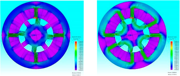
FIGURE 1. Three-phase 12/8 pole SRM flux density distribution map.
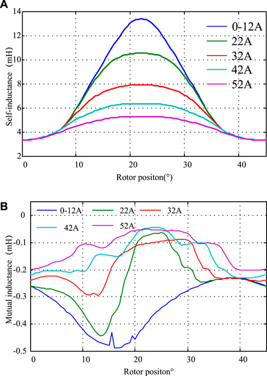
FIGURE 2. Inductance curve of three-phase 12/8 pole SRM.(A) Self-inductance curve profile. (B) Mutual inductance.
As described in Figure 2B, when the adjacent phases are energized simultaneously, mutual inductance appears. It indicates that the absolute value of mutual inductance increases with increasing energized current and the value approaches 8.61% compared with that of self-inductance. Following this, the influence of mutual inductance on self-inductance estimation and position estimation is analyzed. To minimize the effect of mutual inductance, the situation when the voltage pulses are injected synchronously with the sequence of conducting phases should be considered.
This study adopts the pulse injection relationship between phase inductance and rotor position to realize rotor position estimation; therefore, real-time pulse injection phase inductance must be obtained, taking a power converter using a three-phase 12/8 asymmetrical half-bridge circuit switched reluctance motor as an example. First, the following two assumptions are made:
(1) In the pulse injection phase, the switch works in the hard switching mode, that is, the switch of one phase bridge arm is only fully open and fully closed in two states;
(2) The self-saturation of the pulse injection phase can be neglected since the pulse injection frequency is very high and the corresponding pulse current amplitude is very small.
(3) Based on the aforementioned conditions, the two-phase conduction state of the SRM is shown in Figure 3, and in the pulse injection phase, the switching tube is switched on and off, and the voltage equations can be expressed as
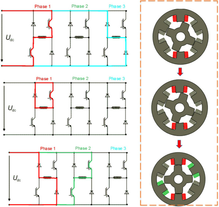
FIGURE 3. Flow diagram of the working mode for three-phase 12/8 pole SRM.
Since the switching period is very short, the current, inductance, and angular speed change is very small. Therefore, it is possible to ignore the changes in the winding resistance, voltage drop, and back EMF during a switching period:
The difference of the current slope between C1 and p in A and B is obtained by the following formula:
When the mutual inductance is neglected, the inductance can be obtained by the lower form:
Therefore, the self-inductance estimation error of the pulse injection phase caused by single-phase mutual inductance can be calculated by the lower model:
In order to reduce the torque ripple of the motor, the SRM is always in the state of two-phase conduction at the same time of phase change. After similar deduction, the self-inductance estimation error caused by the mutual inductance during the two-phase conduction is obtained:
Mode: C2 represents the two-phase conduction phase, and the current slope difference for the C2 phase can be obtained by the lower form:
3.2 Eliminating the Influence of Mutual Inductance in the Drive System
Based on the aforementioned error analysis, this study presents a method for eliminating the mutual inductance of the conduction phase. Its principle and control flow are shown in Figures 4,5, respectively. Ic1 is defined as the actual current at the conducting phase, and ick_up and ick_dn represent threshold values. The power transistor is switched on when the PWMinj is set at a high level, and Enchop stands for enabling signal. The chopping current is synchronized with the pulse injection, which is taken as a synchronous current chopping method.
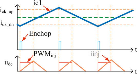
FIGURE 4. Schematic diagram of the synchronous current chopping method.
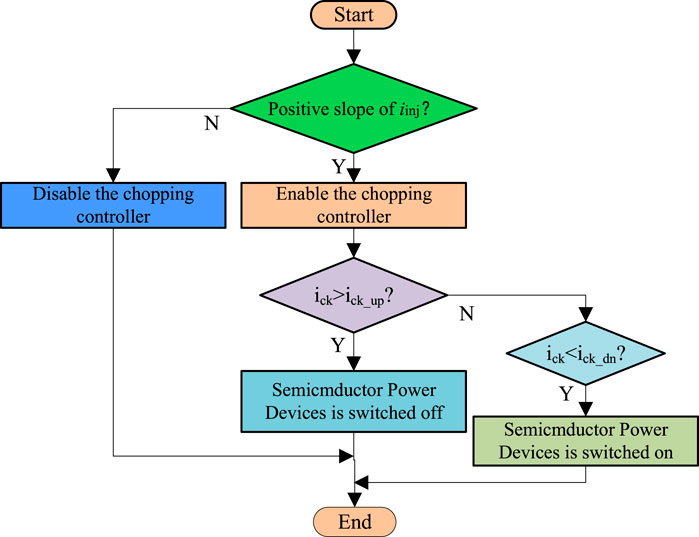
FIGURE 5. Control flow chart of the synchronous current chopping method.
3.3 Three-phase Inductance Partitioning Strategy
The prototype of a three-phase 12/8 structure switched reluctance motor, a motor induction period of 45, a self-cycle is divided into three partitions, each partition has a decline that is sensitive to the change of phase inductance monotonously, and the phase inductance with angle, as shown in Figure 6, using the phase of the partition position estimation. The position of each division in the two-phase estimation of self-partition end-position values at Lhigh and Llow as the top and bottom threshold of self-inductance threshold partition logic can be shown in Table 1, respectively.
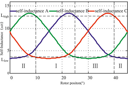
FIGURE 6. Schematic diagram of three-phase self-inductance partitions.
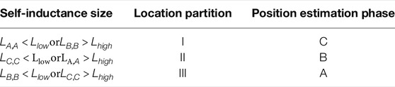
TABLE 1. Self-inductance sub-region logic.
3.4 An Estimation Strategy for Initial Position
The traditional method of initial position estimation usually adopts the method of injecting high-frequency pulse at the same time, ignoring the influence of mutual inductance.
In order to eliminate the influence of injected mutual inductance, when the SRM is in a static state or with an initial speed state, this study adopts the method of injecting pulses into the three-phase winding of the SRM in turn to obtain the three-phase self-inductance in turn. According to the three-phase self-inductance and self-inductance relationship in Table 1, the top threshold Lhigh and the bottom threshold Llow are used to determine the initial position estimation phase, thereby obtaining the initial rotor position.
3.5 Position Estimation Strategy for Driver Operation
During normal driving operation, high-frequency pulses are injected into the non-conducting phase in turn, and the injection interval is the mechanical angle, and there is no interval in which two phases are injected at the same time, so the influence of the injection mutual inductance on the self-inductance estimation of the injected phase is eliminated. The specific process of the algorithm is as follows: first, the initial position is estimated by the initial position estimation strategy, and then the initial position estimation phase and the conduction phase are judged. After starting, the estimated injection phase self-inductance bottom threshold Llow and self-inductance top threshold Lhigh are compared and the position estimation phase is switched.
4 Simulation and Experiment
4.1 Simulation Verification
In order to verify the aforementioned theory, this study uses the JMAG-RT software to establish a Simulink simulation model of the SRM prototype considering the mutual inductance, and based on the motor model, the simulation and verification of the position sensor-less control scheme with and without the proposed method are carried out in Simulink. In the simulation, the pulse injection frequency is 3.3 kHz, the duty cycle is 33%, and the bus voltage is 200 V. In the simulation without using the method in this study, the current chopping frequency is fixed at 4 KHz. During normal driving operation, pulses are injected in the non-conducting region except for the conduction-related discontinuous current interval.
When the motor is in a light-load state (the given current is 25 A), the simulation waveforms of the control scheme using the method in this study and the control scheme not using the method in this study are shown in Figure 7 and Figure 8, respectively. It can be seen that the maximum position errors of the two schemes are distributed at the junction of the inductance partition. Among them, the maximum angle error of the control scheme without the method proposed in this study is about 3.9°, while the maximum position error of the control scheme is about 1.55°. Therefore, the rotor position angle estimated by this scheme is more accurate under light-load conditions.
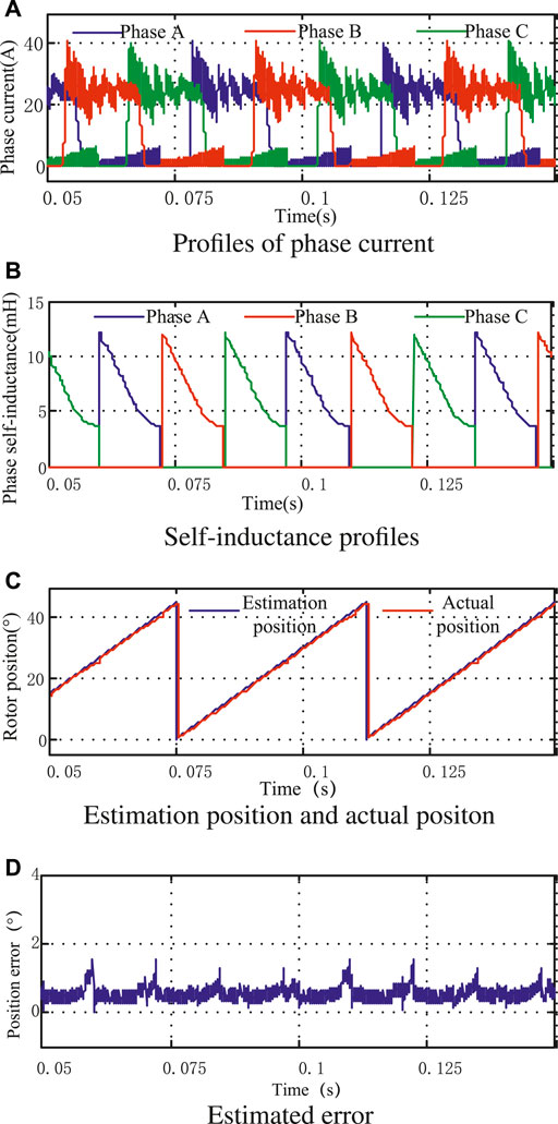
FIGURE 7. Simulation results with proposed estimation under fractional load. (A) Profiles of phase current. (B) Phase inductance profile. (C) Estimation position and actual position. (D) Estimated error.
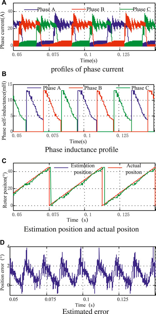
FIGURE 8. Simulation results with the traditional estimation method under fractional load. (A) Profiles of phase current. (B) Phase inductance profile. (C) Estimation position and actual position. (D) Estimated error.
When the motor is under heavy load (the given current is 45 A), the simulation waveform is as shown in Figure 9 and Figure 10. The maximum angle error of the control scheme without the method proposed in this study is about 3.4°, while the maximum position error of the control scheme is about 1.55°, and the maximum position error is also distributed at the junction of the inductor partition. Therefore, this scheme can also estimate the rotor position more accurately under heavy load conditions, and its accuracy is higher than that of the control scheme without the method proposed in this study.
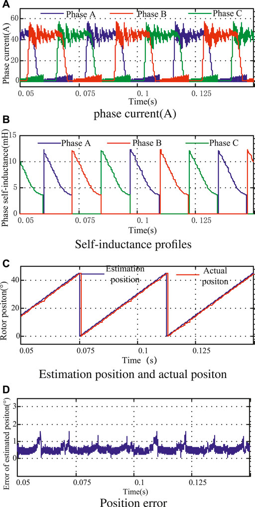
FIGURE 9. Simulation results with proposed estimation under heavy load. (A) Profiles of phase current. (B) Phase inductance profile. (C) Estimation position and actual position. (D) Position error.
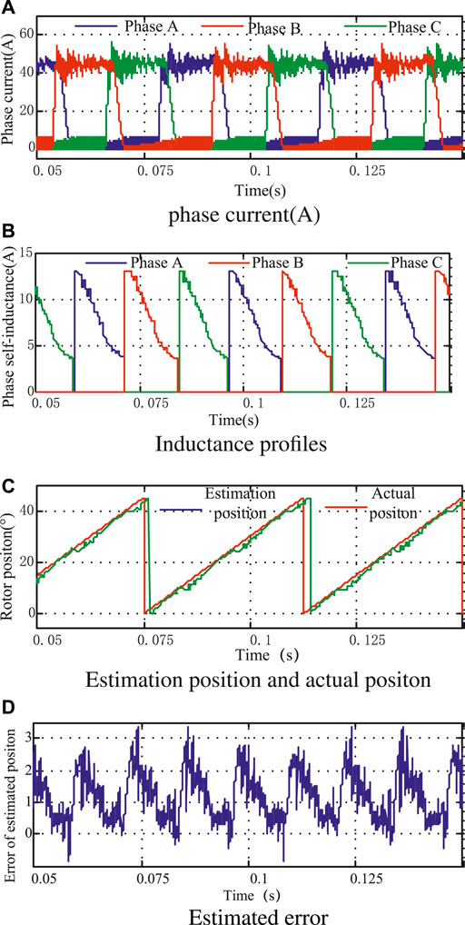
FIGURE 10. Simulation results without proposed estimation under heavy load. (A) Profiles of phase current. (B) Phase inductance profile. (C) Estimation position and actual position. (D) Estimated error.
4.2 Experimental Verification
The experimental motor is a switched reluctance motor with a three-phase 12/8-pole structure, the digital controller is TMS320F28335 from TI, and the power circuit part adopts a traditional asymmetric half-bridge structure. A four-pole-wound resolver is used as a position sensor to easily compare the estimated position with the actual position, with a pulse injection frequency of 3.3 kHz, a duty cycle of 33%, and an open angle. Figure 11 is a physical diagram of the experimental system.
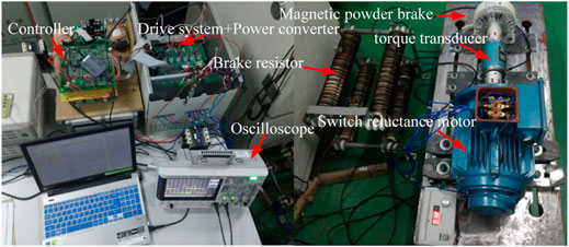
FIGURE 11. Hardware of the experimental system.
Figures 12A,B show the experimental waveforms of the actual position, estimated position, and position estimation error of the rotor with and without the proposed scheme when the given current is 25 A and the rotational speed is about 200 rpm. It can be seen that the maximum position estimation error of the proposed scheme is about 3.1°, while the maximum position estimation error of the proposed scheme is about 5.1°.
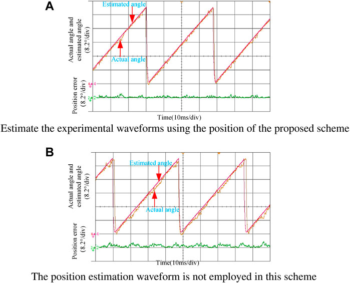
FIGURE 12. Experimental waveforms of rotor position estimation with fractional load. (A) Estimation of the experimental waveforms using the position of the proposed scheme. (B) Position estimation waveform is not used in this scheme.
Figures 13A,B show the experimental waveforms of the actual position, estimated position, and position estimation error with and without the proposed scheme when the given current is 45 A. It can be seen that the maximum position estimation error with the proposed scheme is about 3.6°, and the maximum position estimation error without the proposed scheme is about 4.5°.
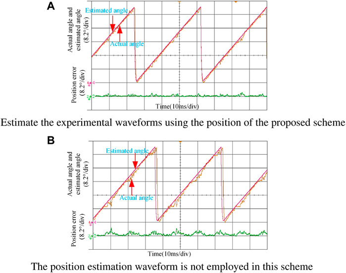
FIGURE 13. Experimental waveforms of rotor position estimation with heavy load. (A) Estimation of the experimental waveforms using the position of the proposed scheme. (B) Position estimation waveform is not used in this scheme
It can be seen from the aforementioned experimental waveforms that the experimental results are consistent with those of theoretical analysis. Compared with the scheme without the method proposed in this study, the proposed method has higher rotor position estimation accuracy in a larger load range.
5 Conclusion
Based on the current slope difference method, this study proposes a position estimation strategy to eliminate the influence of phase mutual inductance on rotor position estimation. The research indicates
(1) Compared with the traditional rotor position estimation method which ignores the influence of interphase mutual inductance, this method can eliminate the influence of interphase mutual inductance on rotor position estimation and has higher estimation accuracy.
(2) Since the relationship between the self-inductance of the pulse injection phase and the rotorposition is used to estimate the rotor position, this method can achieve stable and reliable rotor position estimation in a large load range.
Data Availability Statement
The original contributions presented in the study are included in the article/Supplementary Material; further inquiries can be directed to the corresponding author.
Author Contributions
ZT and MX carried out the concepts, design, definition of intellectual content, literature search, data acquisition, data analysis and manuscript preparation. ML and JLi provided assistance for data acquisition, data analysis and statistical analysis. All authors have read and approved the content of the manuscript.
Conflict of Interest
The author JL was employed by Hunan Creator Information Technologies Co., Ltd.
The remaining authors declare that the research was conducted in the absence of any commercial or financial relationships that could be construed as a potential conflict of interest.
Publisher’s Note
All claims expressed in this article are solely those of the authors and do not necessarily represent those of their affiliated organizations, or those of the publisher, the editors, and the reviewers. Any product that may be evaluated in this article, or claim that may be made by its manufacturer, is not guaranteed or endorsed by the publisher.
References
Betin, F., Capolino, G.-A., Casadei, D., Kawkabani, B., Bojoi, R. I., Harnefors, L., et al. (2014). Trends in Electrical Machines Control: Samples for Classical, Sensorless, and Fault-Tolerant Techniques. EEE Ind. Electron. Mag. 8, 43–55. doi:10.1109/mie.2014.2313752
Cai, J., and Deng, Z. (2012). Sensorless Control of Switched Reluctance Motor Based on Phase Inductance Vectors. IEEE Trans. Power Electron. 27, 3410–3423. doi:10.1109/tpel.2011.2179065
Cai, J., and Deng, Z. (2015). Initial Rotor Position Estimation and Sensorless Control of Srm Based on Coordinate Transformation. IEEE Trans. Instrum. Meas. 64, 1004–1018. doi:10.1109/TIM.2014.2364699
Cai, J., Yan, Y., Zhang, W., and Zhao, X. (2020). A Reliable Sensorless Starting Scheme for Srm with Lowered Pulse Injection Current Influences. IEEE Trans. Instrum. Meas. 70, 1003209.
Chang, Y.-T., Cheng, K. W. E., and Ho, S. L. (2015). Type-v Exponential Regression for Online Sensorless Position Estimation of Switched Reluctance Motor. IEEE/ASME Trans. Mechatron. 20, 1351–1359. doi:10.1109/tmech.2014.2343978
Cheok, A. D., and Ertugrul, N. (2000). High Robustness and Reliability of Fuzzy Logic Based Position Estimation for Sensorless Switched Reluctance Motor Drives. IEEE Trans. Power Electron. 15, 319–334. doi:10.1109/63.838105
Fahimi, B., Emadi, A., and Sepe, R. B. (2005). Four-quadrant Position Sensorless Control in Srm Drives over the Entire Speed Range. IEEE Trans. Power Electron. 20, 154–163. doi:10.1109/tpel.2004.839817
Farshad, M., Faiz, J., and Lucas, C. (2005). Development of Analytical Models of Switched Reluctance Motor in Two-phase Excitation Mode: Extended Miller Model. IEEE Trans. Magn. 41, 2145–2155. doi:10.1109/tmag.2005.848323
Gan, C., Meng, F., Yu, Z., Qu, R., Liu, Z., and Si, J. (2020). Online Calibration of Sensorless Position Estimation for Switched Reluctance Motors with Parametric Uncertainties. IEEE Trans. Power Electron. 35, 12307–12320. doi:10.1109/tpel.2020.2983103
Gan, C., Wu, J., Hu, Y., Yang, S., Cao, W., and Kirtley, J. (2015). Online Sensorless Position Estimation for Switched Reluctance Motors Using One Current Sensor. IEEE Trans. Power Electron. 31, 1. doi:10.1109/TPEL.2015.2505706
Gao, H., Salmasi, F. R., and Ehsani, M. (2004). Inductance Model-Based Sensorless Control of the Switched Reluctance Motor Drive at Low Speed. IEEE Trans. Power Electron. 19, 1568–1573. doi:10.1109/tpel.2004.836632
Hu, K.-W., Chen, Y.-Y., and Liaw, C.-M. (2015). A Reversible Position Sensorless Controlled Switched-Reluctance Motor Drive with Adaptive and Intuitive Commutation Tunings. IEEE Trans. Power Electron. 30, 3781–3793. doi:10.1109/tpel.2014.2342877
Hudson, C. A., Lobo, N. S., and Krishnan, R. (2008). Sensorless Control of Single Switch-Based Switched Reluctance Motor Drive Using Neural Network. IEEE Trans. Ind. Electron. 55, 321–329. doi:10.1109/tie.2007.903965
Jianrong Bu, J., and Longya Xu, L. (2001). Eliminating Starting Hesitation for Reliable Sensorless Control of Switched Reluctance Motors. IEEE Trans. Ind. Appl. 37, 59–66. doi:10.1109/28.903127
Khalil, A., Husain, I., Hossain, S. A., Gopalakrishnan, S., Omekanda, A. M., Lequesne, B., et al. (2005). A Hybrid Sensorless Srm Drive with Eight- and Six-Switch Converter Topologies. IEEE Trans. Ind. Appl. 41, 1647–1655. doi:10.1109/tia.2005.858304
Kuai, S. Y., Zhao, S., Heng, F. P., and Cui, X. (2017). Position Sensorless Technology of Switched Reluctance Motor Drives Including Mutual Inductance. Iet Electr. Power Appl. 11, 1085–1094. doi:10.1049/iet-epa.2016.0490
Mese, E., and Torrey, D. A. (2002). An Approach for Sensorless Position Estimation for Switched Reluctance Motors Using Artifical Neural Networks. IEEE Trans. Power Electron. 17, 66–75. doi:10.1109/63.988671
Mynar, Z., Vaclavek, P., and Blaha, P. (2020). Synchronous Reluctance Motor Parameter and State Estimation Using Extended Kalman Filter and Current Derivative Measurement. IEEE Trans. Industrial Electron. 68, 1972.
Sato, Y., Murakami, K., and Tsuboi, Y. (2016). Sensorless Torque and Thrust Estimation of a Rotational/linear Two Degrees-Of-Freedom Switched Reluctance Motor. IEEE Trans. Magn. 52, 1–4. doi:10.1109/tmag.2016.2536682
Sun, Q., Wu, J., and Gan, C. (2020). Optimized Direct Instantaneous Torque Control for Srms with Efficiency Improvement. IEEE Trans. Industrial Electron. 68, 2072.
Torkaman, H., and Afjei, E. (2013). Sensorless Method for Eccentricity Fault Monitoring and Diagnosis in Switched Reluctance Machines Based on Stator Voltage Signature. IEEE Trans. Magn. 49, 912–920. doi:10.1109/tmag.2012.2213606
Xu, L., and Wang, C. (2002). Accurate Rotor Position Detection and Sensorless Control of Srm for Super-high Speed Operation. IEEE Trans. Power Electron. 17, 757–763. doi:10.1109/tpel.2002.802196
Xue, X. D., Cheng, K. W. E., and Ho, S. L. (2009). Optimization and Evaluation of Torque-Sharing Functions for Torque Ripple Minimization in Switched Reluctance Motor Drives. IEEE Trans. Power Electron. 24, 2076–2090. doi:10.1109/tpel.2009.2019581
Ye, J., Bilgin, B., and Emadi, A. (2015b). An Offline Torque Sharing Function for Torque Ripple Reduction in Switched Reluctance Motor Drives. IEEE Trans. Energy Convers. 30, 726–735. doi:10.1109/tec.2014.2383991
Keywords: double-convex motor, precision control, sensor-less control, rotor position, mutual inductance
Citation: Tao Z, Li M, Xu M, Liu J and Luo J (2022) High-Precision Control for Switched Reluctance Motor With Current Information. Front. Energy Res. 10:894363. doi: 10.3389/fenrg.2022.894363
Received: 11 March 2022; Accepted: 09 May 2022;
Published: 01 July 2022.
Edited by:
Bin Zhou, Hunan University, ChinaReviewed by:
Hui Cai, Changsha University of Science and Technology, ChinaDazhong Ma, Northeastern University, China
Tian-Hua Liu, National Taiwan University of Science and Technology, Taiwan
Copyright © 2022 Tao, Li, Xu, Liu and Luo. This is an open-access article distributed under the terms of the Creative Commons Attribution License (CC BY). The use, distribution or reproduction in other forums is permitted, provided the original author(s) and the copyright owner(s) are credited and that the original publication in this journal is cited, in accordance with accepted academic practice. No use, distribution or reproduction is permitted which does not comply with these terms.
*Correspondence: Mingyi Xu, bWl0Y2hfaHN1QGhvdG1haWwuY29t