- 1Hohai University, Nanjing, China
- 2China Eastern Route Corporation of South-to-North Water Diversion, Beijing, China
- 3Jiangsu Water Conservancy Research Institute, Yang Zhou, China
- 4Harbin Electric Machinery Factory Co., Ltd., Harbin, China
The position of the nozzle in the jet mechanism of the impulse turbine may cause an eccentric jet due to size processing and installation deviations. To study the effect of jet needle eccentricity on the jet, this article first analyzes the jet characteristics of the jet mechanism with different openings (20, 40, 60, 80, 100%) under 4.8% eccentricity, verify the reliability of the research method in this paper. Then the focus is on the jet characteristics of the jet mechanism at different eccentricities (0, 1, 2.1, 4.8, 8, and 14%) at 40% opening. The results show that as the eccentricity of the nozzle increases, the jet appears to be asymmetrical, and the shape of the jet at the inlet section of the runner gradually changes and becomes an irregular shape. The eccentricity of the water jet increases with the increase of the eccentricity of the needle; the efficiency of the injection mechanism gradually decreases, and the energy loss gradually increases. Before the eccentricity of 4.8%, the efficiency decreases more slowly, and after the eccentricity of 4.8%, the rate of efficiency decrease is accelerated.
1 Introduction
Hydropower is the most abundant renewable energy source in the world, accounting for about 20% of the total global electricity production (Mulu, et al., 2012). Among them, the high-head hydraulic resources are very rich in the western region of my country, and the exploitable water head is between 200 and 2000 m (Yang, 2009; Guo et al., 2020). The pelton turbine applied to the high water head has become the first choice, and the jet mechanism is an important part of the pelton turbine, which has an important impact on the overall efficiency of the turbine. The jet of the impingement turbine nozzle is a complex unsteady multiphase flow (Han et al., 2005). If there is a deviation in the size of the injection mechanism, wear of the support device, or unstable system pressure, the central axis of the injection needle will deviate from the central axis of the nozzle, resulting in an eccentric jet (Park et al., 2021; Wang et al., 2021). Deviating from the original jet trajectory, reducing the flow rate of water injected into the bucket, resulting in water flow loss, thereby affecting the jet efficiency of the jet mechanism. Therefore, it is of great significance to study the eccentric jet of jet mechanism of the impingement turbine to improve the efficiency of the impingement turbine.
Research on gas-liquid two-phase free jets (Sun et al., 2021; Zhang et al., 2021; Ouyang et al., 2021; Zhang et al., 2021) is widely used in fluid mechanics calculations. However, most of them focus on the research fields of jet cutting technology and jet atomization (Li et al., 2019; Deng et al., 2016), and the research on jets ejected from nozzles in impingement turbines is still very limited. Li et al. (2003) studied the influence of nozzles of different shapes on the jet performance, Wei et al. (2001) analyzed the influence of jet interference on the efficiency of the runner, providing a basis for the selection and design of impingement turbines. The research on jet eccentricity is mostly the research on the eccentric jet of the pump (Yan and Long, 2010; Du, 2019)and the eccentricity of the needle valve in the injector (Guo et al., 2015). For the research on the eccentricity of the injection needle in the impingement turbine, foreign scholars In Jung, et al. (2019) studied the eccentricity of the injection needle of the impingement turbine, which caused the jet to spread and increased the loss of the nozzle. The quality has a significant effect, but there is no relevant research on the effect of eccentricity and efficiency characteristics.
In this paper, the jet mechanism of the impingement turbine is modeled by UG, and the jet flow under different eccentricities of the nozzle is calculated and analyzed based on FLUENT, To provide a reference for improving the efficiency of the impingement turbine. To study the influence of the eccentricity of the nozzle of the injection mechanism on the jet flow, according to the literature (Jung et al., 2019), it can be seen that the smaller flow rate has a greater impact on the eccentricity of the nozzle, and 20% opening, 40% opening, 60 opening, and 80% opening are selected., The model of injection mechanism with the eccentricity of 4.8% at 100% opening is verified and analyzed. Select 0, 0.22, 0.45, 1, 1.72, 3 mm eccentricity at 40% opening, that is, 0, 1, 2.1, 4.8, 8, 14% eccentricity. Calculate and discuss the influence of different eccentricities of the nozzle on the jet characteristics.
2 Model Setup and Meshing
2.1 Model Parameters
In this paper, the injection mechanism of the impingement turbine with the model CJC601-L-45/2 × 3.5 is used for research. The structural parameters of the model and the experimental data are shown in Table 1.
2.2 Meshing and Mesh Independence Verification
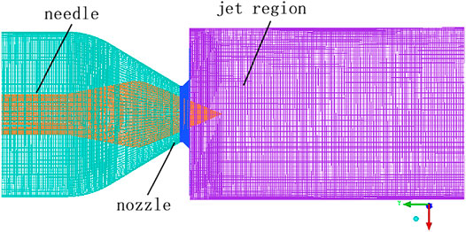
The purpose of fluid meshing is to realize the discretization of the fluid computational domain. The quantity and quality of the meshes will greatly affect the convergence and accuracy of the numerical calculation. The model in this paper is relatively simple, so the structured grid division method is adopted, which has the characteristics of good grid quality, short calculation time, and high calculation accuracy. The injection mechanism model was meshed by ICEM CFD, as shown in Figure 1.
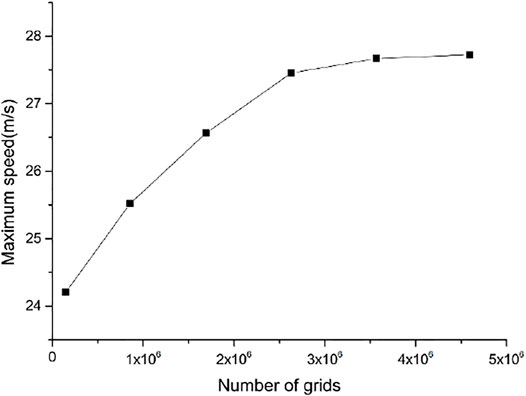
To ensure the accuracy and efficiency of the calculation, it is necessary to verify the grid independence of the grid. The six grid division schemes of the injection model under normal conditions are shown in Table 2. Based on the FLUENT platform, the digital-analog calculation of the six grid division schemes is carried out, and the results are shown in Figure 2. It can be seen that with the increase of the number of grids, the maximum velocity of the jet mechanism is increasing, but after 2.631 million and the number of grids is increased, the increase of the speed does not exceed 0.78%, while the amount of calculation is greatly increased. Therefore, to save the calculation amount while ensuring the calculation accuracy, the fourth grid division scheme is selected, and the number of grids is 2.631 million.
3 Computational Field Settings
3.1 Model Settings
3.1.1 Fluid Basic Governing Equations
For incompressible fluids, the density is constant and the equation is as follows.
Continuity Equation
Momentum equation
Where
3.1.2 VOF Multiphase Flow Model
At present, there are two numerical calculation methods for dealing with the multiphase flow, namely the Euler-Lagrange equation and the Euler-Eulerian equation. The calculation in this paper is that the water jet is injected into the air domain, and the motion of the particles is not involved, so the Euler-Eulerian multiphase flow model in which different phases are processed into an interpenetrating continuum is adopted. In FLUENT, the Euler-Eulerian multiphase flow model is divided into three types, namely the volume of the fluid model (VOF), the Euler model, and the mixture model. The free jet at the nozzle outlet is a two-phase flow of water and air (Ge et al., 2021a). In this paper, water and air are regarded as continuous phases, so the VOF multiphase flow model that can track the free liquid surface of the jet is adopted (Ge et al., 2021b). The model has the advantages of easy implementation, low computational complexity, and high precision. Its governing equation (Ge et al., 2021c) is as follows:
Where, subscripts 1 and 2 represent the gas phase and the water phase, respectively;
3.1.3
The turbulence model is the most widely used in engineering (Han et al., 2021). It includes three types: the standard model, the RNG model, and the achievable model. Compared with the standard model, the RNG model adds a condition to the equation and takes into account the turbulent vortex, which improves the accuracy, so this paper adopts higher confidence and accuracy in a wider range of flows. Accurate RNG model.
The turbulent kinetic energy and dissipation rate equations for the RNG
3.2 Boundary Conditions
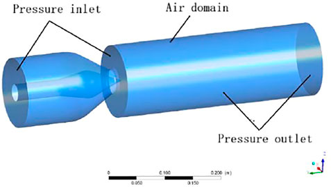
The model boundary conditions are shown in Figure 3.
Inlet boundary conditions: the water inlet is set as the pressure inlet: the pressure is 0.49MPa, the jet inlet is the air domain, and the relative pressure is 0Pa.
Outlet boundary conditions: the outlet is also an air domain, set as a pressure outlet, and the relative pressure is 0Pa.
Wall: The no-slip boundary condition is used for the wall, and the standard wall function is used for the flow in the near-wall region.
3.3 Parameter Definition
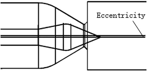
(1) Define the eccentricity as the distance between the central axis of the needle and the central axis of the nozzle, as shown in Figure 4 (the eccentricity in this paper is the radial direction of the needle). The coordinate system and monitoring surface layout are shown in Figure 5.
(2) The eccentricity is defined as the ratio of the eccentric distance to the nozzle radius, as in Formula 10, where l is the eccentric distance and d0 is the nozzle outlet diameter.
(3) To reduce the computational resources, it can be seen from the literature (Li et al., 2003; Liu, 2005) that the jet area is generally set to be about 7 times the diameter of the nozzle outlet. According to the size of the test model used in this paper, 7.4 d0 (y = 30 mm) is defined as the runner inlet.
(4) The pelton turbine is a turbine that uses the kinetic energy of water to do work. The water flow is accelerated through the nozzle and then injected into the atmosphere. Since the jet has no potential energy, all the energy of the water flow is converted into the kinetic energy of the water. Therefore, the theoretical velocity of the jet can be calculated from the head as:
The specific energy loss of the injection mechanism is:
In the formula:
The jet efficiency of this jet mechanism (Liu, 2005) can be defined as
In the formula:
The energy loss rate of the injection mechanism is:
(5) The jet eccentricity is defined as the ratio of the distance from the center of the outgoing water flow from the center axis of the model to the radius of the jet area obtained from the water volume fraction program.
3.4 Solve Settings
This paper is for the unsteady calculation of water-gas two-phase flow, and the time step is set to 0.001s. The solution method adopts the SIMPLE algorithm, which is a semi-implicit method for solving the pressure coupling equation and is also an algorithm generally adopted by various commercial CFD software. The discrete format adopts the first-order upwind discrete format. When setting the relaxation factor, set pressure to 0.3 and momentum to 0.2 to ensure convergence. Since both Fr and We of unsteady flow are relatively large, the influence of gravity and surface tension on the mainstream characteristics is small, so the influence of these forces is ignored in the calculation process in this paper (Ge et al., 2020).
4 Analysis of Numerical Simulation Results
4.1 Calculation Method Validation
It can be seen from the results of previous studies that the eccentricity of the spray needle has a significant effect on the flow at a small flow rate. In this paper, the flow rate is controlled by the opening of the nozzle, and the eccentricity of the nozzle at different openings is calculated to verify the accuracy of the model and calculation method in this paper. The injection models of 20, 40, 60, 80, and 100% opening under 4.8% eccentricity are selected for numerical calculation.
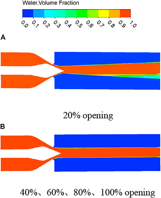
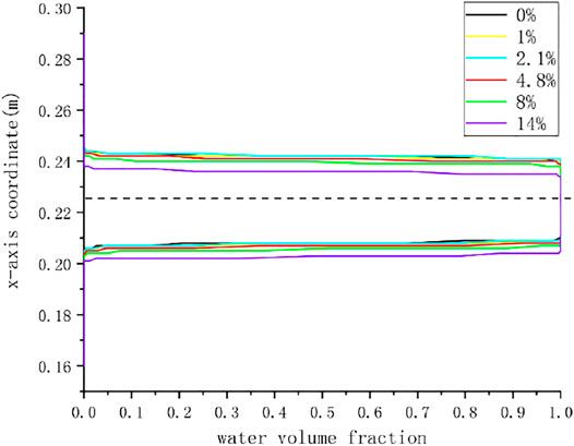
Figure 6 is the gas-liquid two-phase cloud diagram of the eccentric jet of the jet mechanism under different opening degrees, and the figure shows the flow state of water when the jet is stable. The gas-liquid two-phase diagrams are consistent at 40, 60, 80, and 100% opening, and the water flow is stable and symmetrical; but at 20% opening, the jet appears to diffuse significantly, and a piece of air doped with a large amount of air appears. area, which is consistent with the literature results. Figure 7 shows the jet state of the runner inlet at different openings. The water volume fraction on the upper side is smaller at 20% opening, which corresponds to the lower side in the cloud diagram. Due to the serious water flow diffusion, some air is mixed in the middle, causing the water body a reduction in the number of points. It can be seen from the graph that the eccentricity of the nozzle has a greater influence on the small flow rate. With the increase of the jet opening, the curve gradually moves to the center, the two sides are gradually symmetrical, and the influence of the eccentricity on the jet gradually decreases.
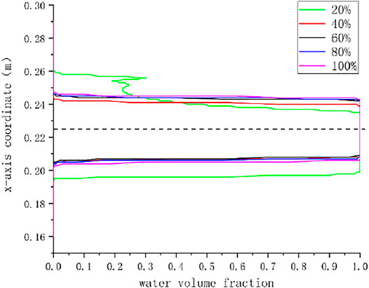
FIGURE 7. The eccentric jet state on the z = 0 mm straight line on the y = 30 mm section under different openings.
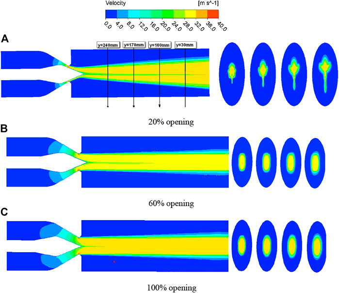
Figure 8 is the velocity cloud diagram of the jet with a z = 0 mm section under three different openings of the selected jet mechanism. It can be seen from the figure that when the opening is 20%, the upper and lower boundaries of the jet velocity of the cross-section appear in the middle of a low-velocity area. This is because the development of the needle boundary layer affects the jet velocity, resulting in a low-velocity area in the middle. However, as the opening increases, the needle The influence of the boundary layer on the jet is gradually reduced, and the middle low-velocity area is gradually reduced; the upper and lower high-speed jet areas are different due to eccentricity, but due to different openings, the influence of eccentricity on the jet is different, and it is more obvious at small openings, while the smaller eccentricity has almost no effect on the jet at large openings; the tail diffusion is more serious at small openings, and the diffusion decreases gradually as the opening increases.
The shape of the jet can be seen from the program of the circular section, which reflects the influence of eccentricity on the shape of the jet. Due to the existence of the spray needle, the water flow shape of the jet outlet section should be annular, and there is a certain distance between the nozzle outlet and the runner inlet, and the annular water flow intersects to form a circular jet area. However, due to the influence of the eccentricity of the nozzle, the shape of the jet at several openings is different. At 100% opening, the shape of the jet is circular, and the influence of the eccentricity can be ignored. At 60% opening, the shape of the jet is close to a circle, but the shape deviation is large at 20% opening. With the continuous development of the jet, the diffusion is serious. Due to the influence of eccentricity, an irregular shape as shown in the figure is formed. It can be seen that the eccentricity has a great influence on the jet flow under the condition of small flow, but has almost no effect under the condition of large flow, which is in line with the previous research and verifies the accuracy of the research method in this paper.
4.2 Flow Characteristics at Different Eccentricities
The quality of the jet directly affects the rotation of the bucket, and the eccentricity of the jet will prevent all the water from hitting the bucket, thereby reducing the efficiency of the turbine and even causing the bucket to be damaged. To study the jet characteristics of the jet mechanism under different eccentricities, this paper selects the jet models with eccentricities of 0, 1, 2.1, 4.8, 8, and 14% at 40% opening for numerical calculation.
4.2.1 Efficiency and Energy Loss of Injection Mechanism
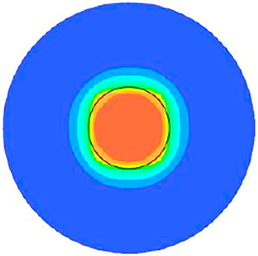
The loss of flow in the pipe caused by the sudden reduction of the nozzle outlet section, the friction loss of the nozzle, and the eccentricity of the spray needle will lead to the eccentricity of the jet so that the loss of water flow that cannot be completely shot on the bucket will lead to a decrease in the efficiency of the spray mechanism. To accurately reflect the efficiency of the eccentric injection mechanism, the average velocity of the central circular section should be selected as the runner inlet velocity. According to Figure 9 it can be seen from the numerical results that the area enclosed by the black circle with the center as the dot and the radius of 22 mm is defined as the effective jet area, which can include the main velocity of the jet. Therefore, the average speed of the area is taken as the speed of the runner inlet.
The calculation conditions are that the nozzle opening is 40%, the water head is 49m, and the theoretical velocity is 31 m/s. The numerical calculation results are shown in Table 3.

TABLE 3. The efficiency and energy loss of the injection mechanism under different working conditions.
Figure 10 shows the efficiency and energy loss rate of the jetting mechanism under different eccentricities. It can be seen from this that with the increase of the eccentricity of the needle, the jetting efficiency of the jetting mechanism is continuously decreasing. It decreases slowly before the eccentricity is 4.8%, and then decreases more quickly. It can be seen that the smaller eccentricity has little effect on the jet. It can be seen from the above that the shape of the jet has only a small change under the smaller eccentricity, but when the eccentricity is large, the shape of the jet changes greatly, resulting in The jet cannot be injected into the water bucket according to the predetermined trajectory, resulting in the loss of water flow energy. Therefore, with the increase of the eccentricity of the spray needle, the efficiency of the spray mechanism will decrease, and the energy loss will increase.
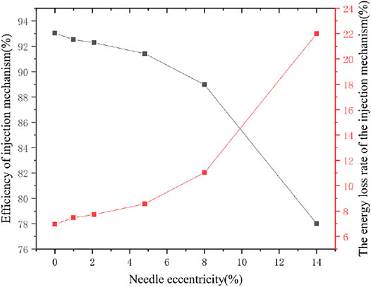
FIGURE 10. The efficiency and energy loss rate of the injection mechanism under different eccentricities.
4.2.2 Jet Flow State Under Different Eccentricity
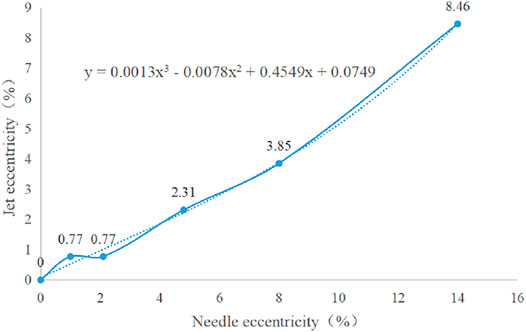
As shown in Figure 11, when the water flow reaches the bucket position under 0, 1, 2.1, 4.7, 8, and 14% eccentricity, the center eccentricity of the water column is 0, 0.5, 0.5, 1.5, 2.5, and 5.5 mm, respectively., the jet area is a cylindrical area with a diameter of 130mm, that is, the jet eccentricity is 0, 0.77, 0.77, 2.31, 3.85, and 8.46%, respectively. Compared with normal without eccentricity, with the increase of needle eccentricity, the jet eccentricity gradually increases, as shown in Figure 12. The increase of jet eccentricity will cause the water flow to fail to shoot on the water bucket completely, resulting in a decrease in the efficiency of the turbine. By fitting the trend line, the water flow eccentricity formula (15) that changes with the change of the eccentricity of the nozzle can be obtained. Because the eccentricity of the nozzle will not increase indefinitely, assuming that the nozzle is ideally attached to the other side of the nozzle outlet, the maximum eccentricity of the nozzle is 42%, and this situation is impossible, and a large eccentricity is easily affected. Found to be overhauled, so only needles with smaller eccentricities will have eccentric jets. Therefore, the eccentricity of 14% is relatively large. The curves fitted by several eccentricities in this paper can completely predict the eccentricity of jets with different eccentricities at 40% opening, which provides a basis for the design of the nozzle and bucket positions.
4.2.3 Speed Characteristics at Different Eccentricities
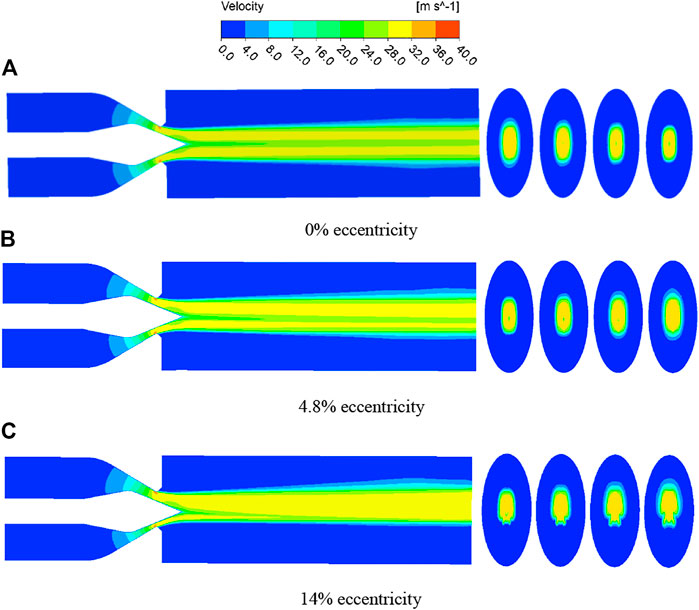
Figure 13 is the velocity cloud diagram of the jet under three different eccentricities of the selected jet mechanism. It can be seen from the cloud diagram that the jet is divided into two high-speed jets. Under normal conditions, the two jets are symmetrical, but in the case of eccentricity, the two jets are no longer symmetrical. The high-speed jet area on one side keeps getting narrower, while the other side keeps getting thicker, and the greater the eccentricity, the more serious the divergence of the tail, 14% of the eccentricity causes the water flow to concentrate almost entirely on one side. The low-velocity zone near the tip of the needle is due to the continuously developing boundary layer on the surface of the needle, which affects the velocity of the jet, resulting in a lower velocity at the center of the jet, but along the direction of the jet, the effect is decreasing (Zeng, 2018).
Figure 14 shows the program of jet velocity in the y = 30 mm section under different eccentricities. The high-speed jet area in the middle is all water phase, and the flow rate is high. The surrounding high-speed area is doped with a lot of air, and the flow rate is low. Therefore, the cloud image with a speed greater than 20 m/s is selected for analysis, and the shape of the jet can also be observed. Due to the influence of the acceleration of the nozzle outlet, the development of the boundary layer of the water flow on the sidewall of the nozzle and the nozzle will be inhibited, forming a flow in the center of the ring, so there will be an area with a small speed in the middle of the cloud image.

FIGURE 14. Velocity cloud diagram of jet velocity greater than 20 m/s in y = 30 mm section under different eccentricity.
However, due to the influence of the eccentricity of the spray needle, with the increase of the eccentricity, the shape of the water flow gradually changes and deviates from the center, and the area with a small intermediate speed will also move in the direction of the deviation of the spray needle, forming Figures 14C–E The effect of moving downwards, the high-speed area above will also move downwards closely. When the eccentricity is serious, the speed of the side with the larger water flow will also be greater, and the high-speed area will follow the middle low-speed area downwards. When moving, it will pass through the low-velocity region, forming the deformed shape of Figure 14F. When it hits the bucket, the water flow in the high-speed area will be offset, resulting in waste of water flow energy, thereby reducing the efficiency of the turbine.
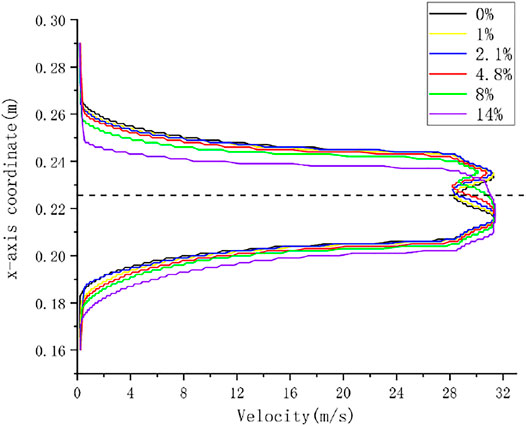
Figure 15 shows the velocity distribution of the jet to the cross-section of the water column on the surface of the bucket, from which we can see the effect of different eccentricities on the velocity that can be jetted to the bucket section. When the eccentricity is small, the velocity distribution is almost the same up and down. With the increase of the eccentricity, the high-speed area of the water flow gradually deviates from the center and moves in the negative direction of the x-axis, and the low-speed area in the middle gradually disappears. The upper and lower velocity distributions are no longer consistent. The results of cloud map 14 are consistent.
5 Conclusion
For the Pelton turbine, the quality of the jet mechanism is the key factor that determines the operation performance of the turbine. Based on the fluent software, this paper uses the VOF multiphase flow model and the RNG turbulence model to study and analyze the eccentric jet characteristics of the jet mechanism under different eccentricities of the needle and different openings. The conclusions are as follows:
(1) The eccentricity has a great influence on the jet flow under the condition of small flow but has almost no effect under the condition of large flow, which is in line with the previous research conclusions and verifies the accuracy of the research method.
(2) With the increase of the eccentricity of the needle, the jet is asymmetrical. When the eccentricity of the jet is small, the jet is concentrated and symmetrical, and when the eccentricity is large, the jet is dispersed; At 40% opening, when the water flow reaches the water bucket position with 0, 1, 2.1, 4.7, 8, and 14% needle eccentricity, the jet eccentricity in the center of the water column is 0, 0.77, 0.77, 2.31, 3.85, and 8.46% respectively. Through curve fitting, the water flow eccentricity formula that changes with the change of the needle eccentricity is obtained:
(3) With the increase of the eccentricity of the needle, the jet shape of the inlet section of the runner changes and gradually becomes an irregular shape, the efficiency of the injection mechanism gradually decreases, and the energy loss gradually increases; before the eccentricity of 4.8%, the efficiency decreases relatively slowly. After 4.8% eccentricity, the jet shape changes greatly, and the rate of efficiency decrease is accelerated.
Data Availability Statement
The original contributions presented in the study are included in the article/Supplementary Material, further inquiries can be directed to the corresponding author.
Author Contributions
HJ: Writing—original draft. ZJ: Formal analysis and editing. CD: Data curation. GX: review. GF: Formal analysis. XB: Investigation. YZ: Supervision.
Funding
Project supported by the following funding: the Central Universities fundamental research funds (2015B02814); the National Natural Science Foundation of China (51339005).
Conflict of Interest
HJ is employed by China Eastern Route Corporation of South-to-North Water Diversion; XB and GF were employed by Harbin Electric Machinery Factory Co., Ltd.
The remaining authors declare that the research was conducted in the absence of any commercial or financial relationships that could be construed as a potential conflict of interest.
Publisher’s Note
All claims expressed in this article are solely those of the authors and do not necessarily represent those of their affiliated organizations, or those of the publisher, the editors and the reviewers. Any product that may be evaluated in this article, or claim that may be made by its manufacturer, is not guaranteed or endorsed by the publisher.
Abbreviations
d, water inlet diameter; d0, Nozzle outlet diameter; d1, Jet outlet air domain; s, Water inlet area; ρ, Density; α, the volume fraction;
References
Deng, H., Feng, F., Wu, X., Yu, X., and Zuo, Y. (2016). Experimental Research on the Impinging Atomization of Gel Propellant[J]. Acta Armamentarii 37 (04), 612–620.
Du, Q. (2019). Application Analysis of Eccentric Jet Pump in Field Production Logging[J]. China Pet. Chem. Stand. Qual. 39 (08), 20–21.
Ge, X., Sun, J., Cai, J., Zhang, L., Zhang, H., Wang, J., et al. (2021a). Study of the Erosion Influence on Bucket Profile and Performance of Pelton Turbine[J/OL]. Proc. CSEE 41 (21), 7391–7403. doi:10.13334/j.0258-8013.pcsee.202212
Ge, X., Sun, J., Li, Y., Wu, D., Zhang, L., and Hua, H. (2020). Numerical Simulation of silt Erosion Characteristics of an Injector of Pelton Turbine[J]. Shuili Xuebao 51 (12), 1486–1494.
Ge, X., Sun, J., Li, Y., Zhang, L., Deng, C., and Wang, J. (2021b). Erosion Characteristics of Sediment Diameter and Concentration on the Runner of Pelton Turbines[J]. Proc. CSEE 41 (14), 5025–5033. doi:10.13334/j.0258-8013.pcsee.201843
Ge, X., Sun, J., Zhou, Y., Cai, J., Zhang, H., Zhang, L., et al. (2021c). Experimental and Numerical Studies on Opening and Velocity Influence on Sediment Erosion of Pelton Turbine Buckets. Renew. Energ. 173, 1040–1056. 1040-1056, ISSN 0960-1481. doi:10.1016/j.renene.2021.04.072
Guo, B., Xiao, Y., Rai, A., Zhang, J., and Liang, Q. (2020). Sediment-laden Flow and Erosion Modeling in a Pelton Turbine injector[J]. Renewable Energy, 162.
Guo, L., Yang, L., Zhou, Z., Song, Y., and Fu, L. (2015). Simulation Analysis on Flow Characteristics inside Nozzle Effected by Eccentric Displacement of Needle[J]. Mod. Vehicle Power (03), 20–26+55.
Han, F., Lin, Z., Xiao, Y., and Kubota, T. (2005). Study on Geometry Prediction of Unsteady Nozzle Jet Flow[J]. Water Resour. Power (03), 14–16+90.
Han, Y., Zhou, L., Bai, L., Shi, W., and Agarwal, R. (2021). Comparison and Validation of Various Turbulence Models for U-bend Flow With a Magnetic Resonance Velocimetry Experiment. Phys. Fluids 33, 125117.
Jung, H., Soo Kim, Y., Ho Shin, D., Taek Chung, J., and Shin, Y. (2019). Influence of Spear Needle Eccentricity on Jet Quality in Micro Pelton Turbine for Power generation[J]. Energy, 175.
Li, G., Wei, C., Liu, J., and Xu, P. (2003). CFD Technique of Nozzle Jet Flow in Pelton Turbine[J]. Water Resour. Power (01), 71–72+79.
Li, J., Lei, F., Zhou, L., and Yang, A. (2019). Effects of Misaligned Impingement on Atomization Characteristics of Impinging Jet Injector[J]. J. Aerospace Power 34 (10), 2280–2293.
Liu, J. (2005). Study on Internal Flow Simulation and Performance of Pelton Turbine[D]. Huazhong University of Science and Technology.
Mulu, B. G., Jonsson, P. P., and Cervantes, M. J. (2012). Experimental Investigation of a Kaplan Draft Tube – Part I: Best Efficiency Point[J]. Appl. Energ. 93. doi:10.1016/j.apenergy.2012.01.004
Ouyang, T., Su, Z., Yang, R., Wang, Z., Mo, X., and Huang, H. (2021). Advanced Waste Heat Harvesting Strategy for marine Dual-Fuel Engine Considering Gas-Liquid Two-phase Flow of Turbine[J]. Energy, 224.
Park, Y., Park, H., Ma, Z., You, J., and Shi, W. (2021). Multibody Dynamic Analysis of a Wind Turbine Drivetrain in Consideration of the Shaft Bending Effect and a Variable Gear Mesh Including Eccentricity and Nacelle Movement[J]. Front. Energ. Res. 8. doi:10.3389/fenrg.2020.604414
Sun, J., Ge, X., Cai, J., Li, L., Zhao, L., Zhang, L., et al. (2021). Analysis of Pressure Pulsation Characteristics of Solid-Liquid Two-phase Flow in Bulb Turbine[J]. Proc. CSEE 41 (22), 7692–7702. doi:10.13334/j.0258-8013.pcsee.202362
Wang, G., Liu, Y., and Liu, Z. (2021). Research and Application of Cold Productivity Formula of Horizontal Well in the Power-Law Fluid Heavy Oil Reservoir. Front. Energ. Res. 9, 792427. doi:10.3389/fenrg.2021.792427
Wei, C., Han, F., Xu, P., and Zhang, Z. (2001). The Study of Jet Interference in Pelton Turbine[J]. J. Huazhong Univ. Sci. Tech. (04), 82–84.
Yan, H., and Long, X. (2010). Numerical Simulation of the Influence of Eccentricity of Nozzle on Jet Pump Performance[J]. Eng. J. Wuhan Univ. 43 (01), 34–37.
Yang, R. (2009). Development Trend of Selection and Application of Turbines for High-Head Power Stations[J]. China Water Power & Electrification (07), 32–34.
Zeng, C. (2018). Research on the Internal Flow Characteristic and Flow Interference in the Pelton Turbine[C]. Tsinghua University.
Zhang, H., Li, W., He, X., Liu, N., and Jin, J. (2021). Numerical Simulation of Gas-Liquid Two-phase Flow in Horizontal Pipeline with Different Diameters[J]. J. Drainage Irrigation Machinery Eng. 39 (05), 488–494.
Keywords: pelton turbine, needle, eccentric jet, eccentricity, JET shape
Citation: Jinwei H, Xinfeng G, Dongdong C, Jing Z, Bing X, Fei G and yuan Z (2022) Research on the Effect of Needle Eccentricity on the Jet Flow Characteristics. Front. Energy Res. 10:882747. doi: 10.3389/fenrg.2022.882747
Received: 24 February 2022; Accepted: 21 March 2022;
Published: 06 April 2022.
Edited by:
Ling Zhou, Jiangsu University, ChinaReviewed by:
Deyou Li, Harbin Institute of Technology, ChinaParvathy Rajendran, Universiti Sains Malaysia Engineering Campus, Malaysia
Kh S. Mekheimer, Al-Azhar University, Egypt
Copyright © 2022 Jinwei, Xinfeng, Dongdong, Jing, Bing, Fei and yuan. This is an open-access article distributed under the terms of the Creative Commons Attribution License (CC BY). The use, distribution or reproduction in other forums is permitted, provided the original author(s) and the copyright owner(s) are credited and that the original publication in this journal is cited, in accordance with accepted academic practice. No use, distribution or reproduction is permitted which does not comply with these terms.
*Correspondence: Ge Xinfeng, Z2V4aW5mZW5nQGhodS5lZHUuY24=
 Huang Jinwei1,2
 Ge Xinfeng
