 Kun Zhang
 Xiaoliang He
 Liangbi Wang
 Yan Yu3
- 1School of Mechanical Engineering, Lanzhou Jiaotong University, Lanzhou, China
- 2Key Laboratory of Railway Vehicle Thermal Engineering of MOE, Lanzhou Jiaotong University, Lanzhou, China
- 3College of Environmental Sciences and Engineering, Dalian Maritime University, Dalian, China
Detailed experimental investigation is presented for the heat transfer characteristics of an inclined shell-and-tube phase-change thermal energy storage unit. For the case of inclined angle α = π/4, the solid–liquid interface presented a concave surface because the heat transfer can be affected not only by conduction in the phase-change material (PCM) domain but also by natural convection significantly. The heat transfer rate increases with the increasing flow rate and inlet temperature of heat transfer fluid (HTF), but the flow rate of the HTF has little effect on the charging process for the case of qv ≥ 40 L/h. The heat transfer rate of PCM above the HTF tube increases with the increase of inclined angle. The effects of inclined angle on the heat transfer rate can be not negligible due to the obvious natural convection in the charging process.
Introduction
Phase-change energy storage technology have been the topic of many investigations until recently since it has many industrial applications including aerospace, air conditioning and refrigeration, solar heat storage system, and building heating. A large number of literatures on both experimental and numerical studies were published in the past few decades (Farid et al., 2004; Rehman et al., 2019; Sharma et al., 2020). Ji et al. (Ji et al., 2018) studied the phase change charging process in the latent heat energy storage device by setting the internal double fin length in the numerical method. Natural convection in the latent heat energy storage device can be significantly enhanced and has obvious chaotic characteristics when the fin length ratio was less than 1. Han et al. (Han et al., 2017) numerically studied the heat storage performance of shell-and-tube phase change energy storage devices. It is found that the increase of HTF inlet temperature accelerates the heat transfer rate in the charging process, and the natural convection in a liquid domain can lead to uneven distribution of the solid–liquid interface. Xie and Choo (Xie et al., 2019) numerically investigated the effect of natural convection on the thermal behavior of a PCM-based heat sink with novel tree-shape conductive structures and convectional plate-fin structures. Their results indicated that the effect of natural convection was related to the metal structure, orientation, and metal volume fraction. Jmal et al. (Jmal and Baccar, 2018) studied the solidification process of PCM in rectangular assemblies with vertical fins. Their results indicated that the influence of natural convection on the solidification process of PCM cannot be neglected, and the effect of fins on the solidification process is not obvious. Agyenim et al. (Agyenim et al., 2009) studied three kinds of phase-change energy storage devices, namely, energy storage devices without enhanced heat transfer, energy storage devices with circular fins, and energy storage devices with longitudinal fins. It is found that the energy storage device with longitudinal fins has the best performance in the energy storage process. Wooszyn et al. (Wooszyn et al., 2021) studied a new double-tube latent heat thermal energy storage unit and compared the melting time and efficiency of eight different schemes. It is found that the new double-tube latent heat thermal energy storage units can significantly shorten the melting time of PCM compared with the three structures of horizontal, vertical, and spiral winding. Based on the abovementioned literature research content, the results indicated that natural convection can affect the heat transfer rate and heat exchange efficiency, while the orientation of the heat storage device also expressed a significant impact on the heat transfer rate by impacting the natural convection in the charging process.
Experimental and numerical studies on phase-change heat transfer for different placement angles of heat exchangers have been studied by many researchers. Kothari et al. (Kothari et al., 2021,) studied the effect of inclined angle on the thermal performance of four types of rectangular-finned phase-converter heat exchangers through experiments. It is found that the inclined angle of the heat exchanger has a major effect on the thermal characteristics of the heat exchanger without fins, but the effect was less significant for the finned heat exchanger, especially the three-fin heat exchanger. Sathe et al. (Sathe and Dhole, 2019,) investigated the charging process of PCM in a top-heated rectangular inclined angle fin heat exchanger. It is found that the melting time of the PCM gradually increased with the decrease of the inclined angle, and the average temperature of the PCM decreased with the decrease of the inclined angle. Avci et al. (Avci and Yazici., 2018) studied the effect of inclined angle on the thermal characteristics of flat plate phase-change heat exchangers and ordinary heat exchangers. The inclined angle has a significant effect on the thermal performance of the phase-change heat exchanger, but the effect on ordinary heat exchangers is negligible. Kamkari et al. (Kamkari et al., 2014) studied the charging process in a rectangular phase-change heat exchanger at various inclined angles. It is found that the inclined angle has a significant effect on the formation of natural convection, and as the inclined angle decreases, a chaotic flow structure gradually appears. Zennouhi et al. (Zennouhi et al., 2017) studied the charging process in a rectangular heat exchanger with diverse inclined angles through two-dimensional numerical simulations. It is found that the melting rate of PCM increased with decreasing inclined angles. Joneidi et al. (Joneidi et al., 2017) experimentally studied the effect of inclined angle heat flux in a rectangular phase-change heat exchanger. Karami et al. (Kamkari and Kamkari., 2018; Karami and Groulx., 2018) numerically and experimentally investigated the effect of the inclined angle on the charging process of PCM in finned latent heat thermal storage units. Their results indicated that the melting time can be shortened by decreasing the inclined angle of the thermal storage unit due to the intensification of the natural convection flows.
However, most of the previous studies focused on the characteristics of heat transfer in inclined rectangular phase-change thermal storage units, and only in a few of the works, the effect of inclined angle on the charging process in a shell-and-tube phase-change heat storage unit was considered in detail. Pahamli et al. (Pahamli et al., 2017) studied the charging process of PCM in shell-and-tube phase-change thermal energy storage units. It is found that with the progress of the PCM charging process, buoyancy gradually leads the PCM charging process and that increasing the dip angle shortened the PCM charging time. Sharifi et al. (Sharifi et al., 2013) investigated the charging process of cylindrical phase-change heat exchangers. Their results indicated that the proper placement orientation of the device obviously affects the temperature distribution within the PCM, and the change of the solid–liquid interface over time is also significantly different because of the three-dimensional flow in the liquid PCM. Siyabi et al. (Siyabi et al., 2019) studied the charging process of the cylindrical phase-change heat storage unit using a combination of experimental and numerical simulation methods. Their results indicated that the inclined angle of the thermal storage unit has a major influence on the PCM temperature distribution, charging time, and the profile of the solid–liquid interface. Kousha et al. (Kousha et al., 2017) studied the performance of shell-and-tube phase-change heat exchangers with varying inclined angles. It is found that the change of the inclined angle did not affect the heat transfer rate and the temperature change during the solidification process, and the heat transfer rate of the thermal energy storage unit in the horizontal state was greater than that of the heat exchanger in the vertical state during the charging process, and the solidification process was reversed. Mehta et al. (Mehta et al., 2019) studied the effect of inclined angle on the charging process of PCM in a shell-and-tube phase-change energy storage device. Their results indicated that the inclined angle significantly affects the thermal storage process, and the time required for the PCM to melt and store energy is the least when α = π/4. The abovementioned studies mainly focus on the effect of the inclined angle on heat transfer but do not explore the effect of variables such as inlet temperature and flow rate on heat transfer under a certain inclined angle.
The objective of this study is to explore the effects of inlet temperature and HTF flow rate on heat transfer in shell-and-tube phase-change heat storage units at different inclined angles. The temperature changes under different conditions are obtained using thermocouples placed inside the heat storage unit. The effects of inlet temperature and HTF flow rate on the heat storage rate of the inclined heat storage unit will be investigated in detail.
Experimental Systems
Experimental Model
A schematic diagram of an experimental model under consideration is shown in Figure 1, which comprises the plain tube inside a cylindrical envelop forming a shell-and-tube storage unit. The PCM is placed into the shell while the HTF flows inside the tubes. The PCM around the HTF tube can absorb thermal energy from the hot HTF via the tube surface as a result of the temperature difference between the hot fluid and PCM. The PCM starts melting when the temperature reaches the melting point. The inclined angle between the central line of the shell-and-tube unit and horizon is set to α = π/4. Several different inlet temperatures and flow rates will be investigated in experiments.
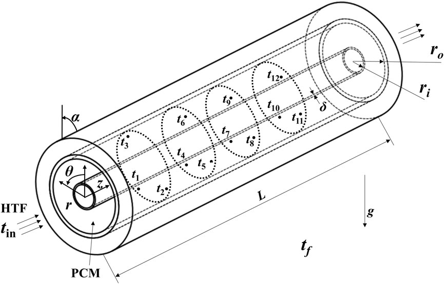
FIGURE 1. Schematic diagram of the inclined angle shell-and-tube phase-change thermal energy storage unit.
Experimental Setup
The whole experimental device comprises a constant temperature water tank, an ice bucket, a set of hot water pipes, a flow meter, a data acquisition instrument, 14 self-made T-type thermocouple lines, and a shell-and-tube phase-change thermal storage unit (test section), as shown in Figure 2. The test section consists of two coaxial tubes: the inner tube is a smooth tube made of red copper which has a 32 mm outer diameter and a 2 mm wall thickness, and the outer tube adopts an acrylic tube with an outer diameter of 100 mm, wall thickness of 5 mm, and length of 500 mm. The liquid flowing in the copper pipe is water, and the annular space between the copper pipe and the acrylic pipe is filled with paraffin. A layer of 20-mm-thick rubber plastic insulation material is wrapped on the outer wall of the acrylic circular pipe for the purpose of decreasing the heat transfer loss. The ice bucket is used to keep the cold end of the thermocouple at 0°C.
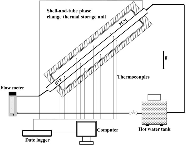
FIGURE 2. Schematic diagram of the experimental setup.
The experimental material used is OP44E, which has stable properties, high energy storage capacity, good cycle stability, and no supercooling and precipitation phenomenon. The thermophysical properties of PCM given by the manufacturer are shown in Table 1.
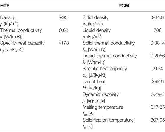
TABLE 1. Thermophysical properties of HTF and PCM.
Experimental Procedure
Instrumentation With Data Acquisition System
In order to accurately obtain various parameters required by the experiment, various experimental instruments are selected to be installed on the experimental device. A total of 12 T-type thermocouples are arranged in the annular area between the tubes and shells. Thermocouples were grouped into four groups. Three thermocouples in every group were located at the same axial distance, while the insertion depth was different. The location of 12 thermocouples is shown in Table 2. All the T-type thermocouples were calibrated for use, and they were observed to have a measuring range of 5–85°C and accuracy of ± 0.2°C. The thermocouple depth error was ±0.5 mm at the same height of PCM. These thermocouples are used to measure the temperature change during the whole experiment.
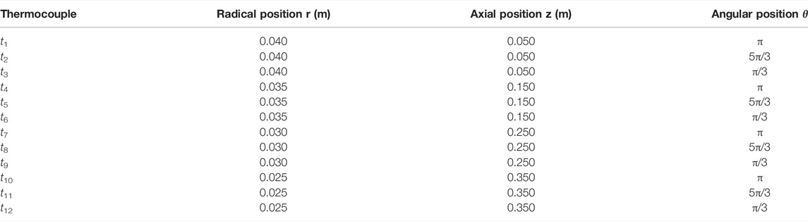
TABLE 2. Axial, angular, and radial positions of thermocouples.
The data acquisition system consists of a 40-channel differential multiplexing module with automatic CJC and a DAQ6510 data acquisition instrument produced by Keithley Instrument Company. The data acquisition system can directly save the measured voltage data to the USB flash disk, and then the data on the USB flash disk are arranged on the computer. The flow rate of the HTF is measured by a glass rotameter, and there is a manually controlled valve to control the water flow in the water pipe. The instrument accuracy class of the LZB-15 variable area flowmeter is ± 2.5%.
Repeat Experiments
Several repeated experiments under the same working conditions were conducted for verifying the experimental repeatability. When the values of inlet temperatures were 58.2°C, 63.1°C, 67.4°C, 73.1°C, 77.7°C, and 83.0°C, the repeated experiments are kept at almost the same conditions of flow rate 40 L/h and inclined angle 45°C. The maximum differences of inlet temperature at repeated experiments were all less than 0.4°C, and the corresponding differences inflow rate can be controlled in the scope of 2 L/h. Figure 3 shows the value of PCM-averaged temperature difference between repeated and first experiments varies with time for different inlet temperatures. For the case of tin = 63.1°C, the maximum difference of averaged temperature was 1°C at τ = 383 min, and its relative difference of averaged temperature was less than 1%. The maximum difference increases with the increasing value of inlet temperature. When the value of inlet temperature reached 83°C, the maximum difference of averaged temperature was 1.5°C and the relative difference was approximately 2.2% at τ = 102 min. The results indicated that the results of repeated experiments agreed very well with those of the first experiment, and the experiments have good repeatability. It is mentioned that the phase-change thermal storage unit is cooled in the environment and the values of initial temperature at different experiments are equal to the values of ambient temperature. Therefore, there exists an initial temperature difference at different inlet temperatures, and the maximum difference of initial temperature for all the cases is less than 7°C. The effect of initial conditions is not considered in this investigation because it has a limited effect on the temperature distribution.
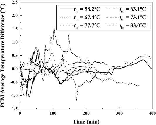
FIGURE 3. Timewise variation of an averaged temperature difference between first and repeated experiments.
Experimental Steps
The phase change material OP44E is selected and injected into the acrylic pipe with a syringe before the experiment. When the annular space of the shell-and-tube thermal energy storage unit was filled with phase-change material in form of liquid, the injection hole was sealed by a rubber stopper. The liquid PCM gradually turned into solid because the ambient temperature is below the melting temperature. Once assembled, the entire thermal storage devices, including the top and bottom, were covered with 20 mm of thermal insulation material. According to the design of the experimental setup, all experimental equipment was checked before a new test. The whole experimental devices were placed in the laboratory for over 10 h so that the temperature of all measure points and environment was virtually the same. The liquid was heated to a fixed value of temperature by a hot water tank before turning on the valve. The temperature values of monitor points can be recorded by using a data acquisition system (DAQ6510, United States) every 10 seconds. When the valve was turned on, the hot water flowed into the shell-and-tube thermal energy unit at a rate of 40 L/h. The hot water released its heat to the PCM, and then the cooled water was routed back to the water tank. The experiments were terminated when the solid PCM was entirely converted into liquid and the change of temperature values was not obvious.
Results and Discussion
Charging Process
Figure 4 shows the transient temperature during the charging process at different points when the inclined angle was π/4 and the inlet temperature was 63.1°C. The temperature of PCM in annular space was almost the same at the initial time because they were placed in the room temperature environment for over 10 h. The heat in the PCM domain could mainly be transferred by way of heat conduction in the initial stage of the experiment. The results showed that the change of temperature at the t10 position is more obvious than that at the t1 position because although the t10 position is far away from the HTF inlet, it is closer to the copper tube than the t1 position, which shows that the closer the position is to the copper tube, the more obvious the change of temperature is. The temperature of PCM increased due to the increase of sensible heat and then reached the melting temperature of PCM. The heat of the HTF began to be gradually absorbed by the latent heat of PCM. The value change of PCM temperature was small during the transition process from solid to liquid. It can be seen from this figure that the lower the horizontal position is, the more time the transition process takes. The transition process for t1 lasts from 100 to 320 min, while the corresponding duration was less than 100 min. This is because the charging process started from the top of the PCM annular cavity due to the influence of natural convection. The solid PCM finally changed to liquid completely, and the heat of HTF began to be absorbed by PCM in the form of sensible heat again. The PCM temperature at all measure points rose rapidly, and natural convection in the PCM domain began to dominate the heat transfer process. The PCM solid–liquid interface was impacted by the natural convection of liquid PCM and distance from the inner HTF tube at the same time, thus forming a concave solid–liquid interface. When the PCM temperature was close to the HTF inlet temperature, the heat transfer in the thermal energy storage unit reached a steady state and after that, the value of temperature was the same all the time. In addition, the ambient temperature remained almost unchanged for all the working conditions, but because the experimental equipment could not be in a completely adiabatic state, the ambient temperature would have an impact on the charging process to a certain extent. It can be seen from the figure that when the temperature no longer changes with time, the final value of PCM temperature with different inlet HTF temperature has some discrepancies. However, the effects of ambient temperature on the heat transfer rate and transient temperature of PCM are not very obvious. The abovementioned experimental results indicated that the strength of natural convection and the distance from the HTF tube were two important factors affecting the heat transfer rate, temperature distribution, and solid–liquid interface. This natural convection phenomenon existed in the whole charging process and could obviously accelerate the charging of PCM.
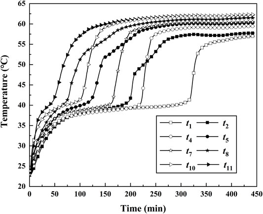
FIGURE 4. Transient temperatures during the melting process at some points for tin = 63.1°C, α = π/4.
Figure 5 shows the temperature difference between the inlet and outlet of the HTF. It can be seen that the inlet temperature of the HTF was higher than the outlet temperature during the whole charging process. The temperature difference reached the maximum value of 12.8°C at 2.1 min. This is because the thermocouple probe was fixed on the copper tube wall and delayed response of the probe was inevitable. The temperature difference between the inlet and outlet of the HTF began to decrease after that time. The decreasing speed decreased gradually due to the decreasing temperature gradient near the tube wall. The temperature difference was less than 1°C after 17.4 min. Finally, the temperature difference was kept the same after 30 min. The phase-change material in annular space was completely melted at that time, and the heat transfer in the thermal energy storage unit reached a steady state while the temperature difference can be attributed to the heat loss from the external environment. The heat storage quantity of the thermal energy storage unit can be used for evaluating the thermal storage efficiency. It can be estimated as follows:
where ρl, qv, cp tin, tout, and τ denote liquid density, volume flow rate, specific heat capacity of water, HTF inlet temperature, HTF outlet temperature, and experimental duration, respectively. The change of heat absorbed by the heat storage unit with time is shown in Figure 6. The heat storage quantity increased with time, while the rate of change of it decreased gradually. The heat transfer rate at the beginning of the experiment is highest in the changing process due to the obvious temperature difference between HTF and PCM and high thermal conductivity in the solid form of PCM. The heat transfer became to be dominated by natural convection when most of the annular space was filled with liquid PCM. The heat transfer rate gradually decreased with time and almost was the same after 300 min since the temperature difference between the inlet and outlet HTF was very small. The heat storage quantity reached 1716.2 KJ.
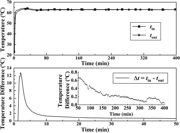
FIGURE 5. Transient temperature and temperature difference of the inlet and outlet HTF during the melting process for α = π/4.

FIGURE 6. Timewise variations of total heat storage during the melting process.
Effect of Flow Rate
The effect of flow rate on the heat transfer of thermal energy storage units was studied for the case of tin = 63.1°C and α = π/4. Figure 7 showed that the time required for PCM average temperature reached different values with the different volume flow rates. It can be seen that the required time decreased with the increasing flow rate from 10 L/h to 40 L/h when the average temperature reached certain values, such as 35°C, 40°C, 45°C, and 50°C. The time discrepancies of different volume flow rates became obvious gradually. The required time difference at the average temperature of 30°C for the case of volume flow rates 10 L/h and 40 L/h was less than 3 min, while the corresponding temperature difference increased over 30 min. The results indicated that the heat transfer rate in thermal energy units can be significantly affected by volume flow rate, and it increases with the increasing volume flow rate. The value of temperature rise for qv = 40 L/h was greater than that for the case qv = 10 L/h per unit time because of more heat-absorbing amount. However, when the volume flow rate increased to 80 L/h, the curves of required time for 40 L/h and 80 L/h are almost the same. It means that the increasing flow rate cannot improve the heat transfer rate in the thermal energy storage unit. The thermal resistance in the PCM domain under those conditions was far more than the thermal resistance in the HTF domain for the whole charging process. Therefore, the effect of HTF volume flow rate on heat transfer can be negligible for the case of qv ≥ 40 L/h. Because the pressure loss of the HTF increased with the increasing flow rate and the flow required more pumping power under the higher flow rate, the volume flow rate of 40 L/h was chosen for all the subsequent experiments.
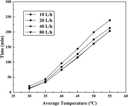
FIGURE 7. Time required for PCM average temperature reached at different values for tin = 63.1°C, α = π/4.
Effect of Heat Transfer Fluid Inlet Temperature
The effect of different HTF inlet temperatures on the charging process was studied in this section. The melting experiment of the PCM thermal energy storage unit for the case of inclined angle α = π/4 was carried out for different inlet temperatures. The measured values of inlet temperature by the thermocouple are 57.9°C, 63.1°C, 67.8°C, 73.1°C, 77.7°C, and 82.4°C. The transient temperatures at t1, t2, t10, and t11 during the charging process for different inlet HTF temperature are shown in Figure 8. The transient temperature of thermocouples t3 and t12 was not shown because the two thermocouples were symmetric to the t2 and t11, and the variation curve of temperature versus time was almost the same. At the initial stage of melting, the change of temperature for all the thermocouples was quite obvious due to the heat transfer dominated by thermal conduction. As melting advances, natural convection began to develop and the strength of natural convection increased with the increasing molten PCM. The key heat transfer mechanism was natural convection in this stage. Finally, the curve of temperature versus time became a straight line, and the heat transfer in the thermal energy storage unit reached a steady state. It can be seen in Figures 8A,B that the rate of temperature rise at t2 is significantly faster than the rate at t1. This is because natural convection plays a major role in the charging process. The thermocouple t2 was above the HTF tube, while the t1 was under the HTF tube. The natural convection nearby t1 was suppressed by the upper wall of HTF with higher temperatures. On the contrary, the natural convection of PCM nearby t2 can be improved because of the heated lower wall. A similar phenomenon can be observed in Figures 8C,D. The rate of temperature rise at the same thermocouple increased with increasing inlet HTF temperature. It means the heat transfer rate and natural convection can be improved by increasing the temperature difference between HTF and PCM.
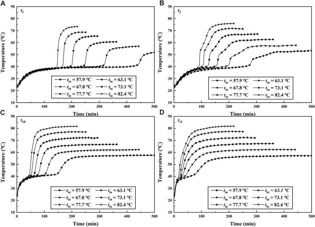
FIGURE 8. Transient temperatures with different HTF inlet temperatures during the melting process for qv = 40 L/h, α = π/4.
Table 3 showed the time required for the temperature values of all the thermocouples and the averaged value of those thermocouples attained to 50°C. When the inlet HTF temperatures was 57.9 and 77.7°C, the required time for the PCM average temperature attained to 50°C was 269.7 and 63.1 min. It means the effect of inlet HTF temperature on the heat transfer rate is significant in the whole charging process. When the temperature of t1 for the case of tin = 77.7°C reached 50°C, it cost 172.8 min which was much longer than the costing time of 23.8 min for the case of t12 under the same working conditions. The discrepancies in temperature variation of the two thermocouples mainly depended on their positions in the inclined thermal energy storage unit. Although the thermocouple t12 was far away from the entrance of the HTF, the t12 was near the wall of the HTF tube and moreover, it was fixed at the upper part of the PCM domain. Therefore, the PCM nearby t12 can cost the minimum time for attaining a certain value of temperature, and heat transfer was significantly rapid in this region. The results indicated that the melting time decreases with the increasing inlet HTF temperature and the heat transfer rate above the HTF tube was affected by natural convection significantly.
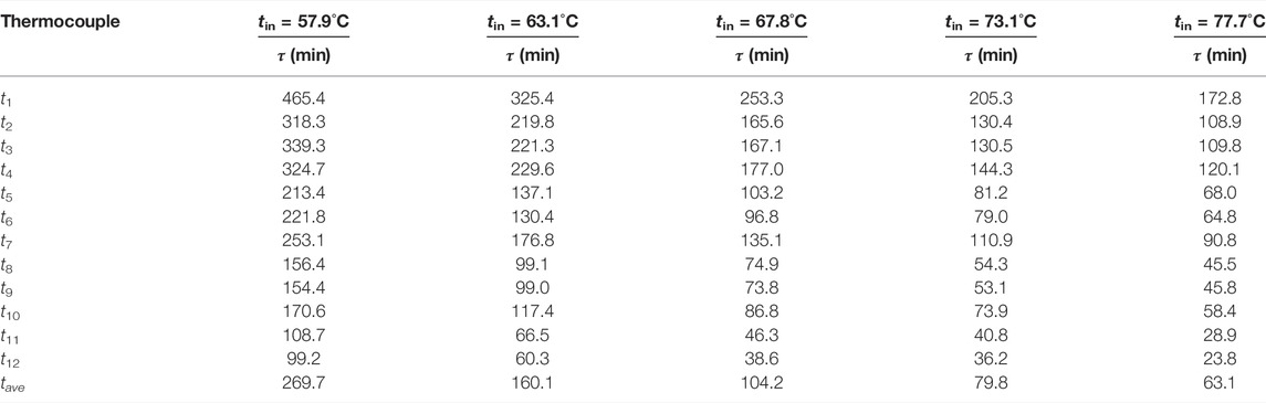
TABLE 3. Time required for the PCM temperature attained to 50°C.
Effect of Inclined Angle
Figure 9 shows the effect of inclined angle on the transient temperature at t3, t6, t9, and t12 for the case of tin = 63.1°C and qv = 40 L/h. The four thermocouple probes in the PCM domain were fixed over the inner HTF tube, except for the vertical thermal energy storage unit. Although there are some discrepancies in initial temperature in every experiment, it could not significantly affect the temperature at every monitor point. The value of temperature rose obviously in the beginning stage of the experiment because the heat transfer is dominated by thermal conduction and the PCM has a high thermal conductivity in the form of solid. The melting rate above the HTF tube increased with the increasing inclined angle. This phenomenon was due to the influence of natural convection on the heat transfer rate when the solid PCM began to melt. For the measure temperature point t3, the required time in a vertical unit for arriving at the unchanged value of temperature was about 400 min, while the required time in the horizontal unit was less than 150 min. The strength of natural convection is related to the orientations of temperature gradient and gravity. For the horizontal case, the bottom wall was heated and the top wall was adiabatic. It was beneficial to the development of natural convection above the HTF tube and thus improves the heat transfer rate in this domain. Therefore, the rising rate of the temperature at t3 for the vertical unit was less than that at the same point for the horizontal unit, as is shown in Figure 9A. Some similar results for transient temperature, heat transfer rate, and natural convection can be obtained in Figures 9B,C. However, it seems not to conform to the abovementioned regular results for the temperature measurement point t12 in Figure 9D. The difference in temperature values at t12 was not obvious for the cases with different inclined angles. The reason for this was related to the location of the measured temperature point. The point t12 was fixed nearby the HTF tube wall, and the natural convection here was relatively weak due to the effect of viscous force. The heat transfer was dominated by thermal conduction nearby the HTF tube wall, and thus the heat transfer rate in this region was regarded to be irrelevant to the inclined angles. The results indicated that the strength of natural convection above the HTF tube can be the effect of the inclined angle of the unit. The effects of inclined angle on the heat transfer rate cannot be negligible due to the obvious natural convection in the charging process.
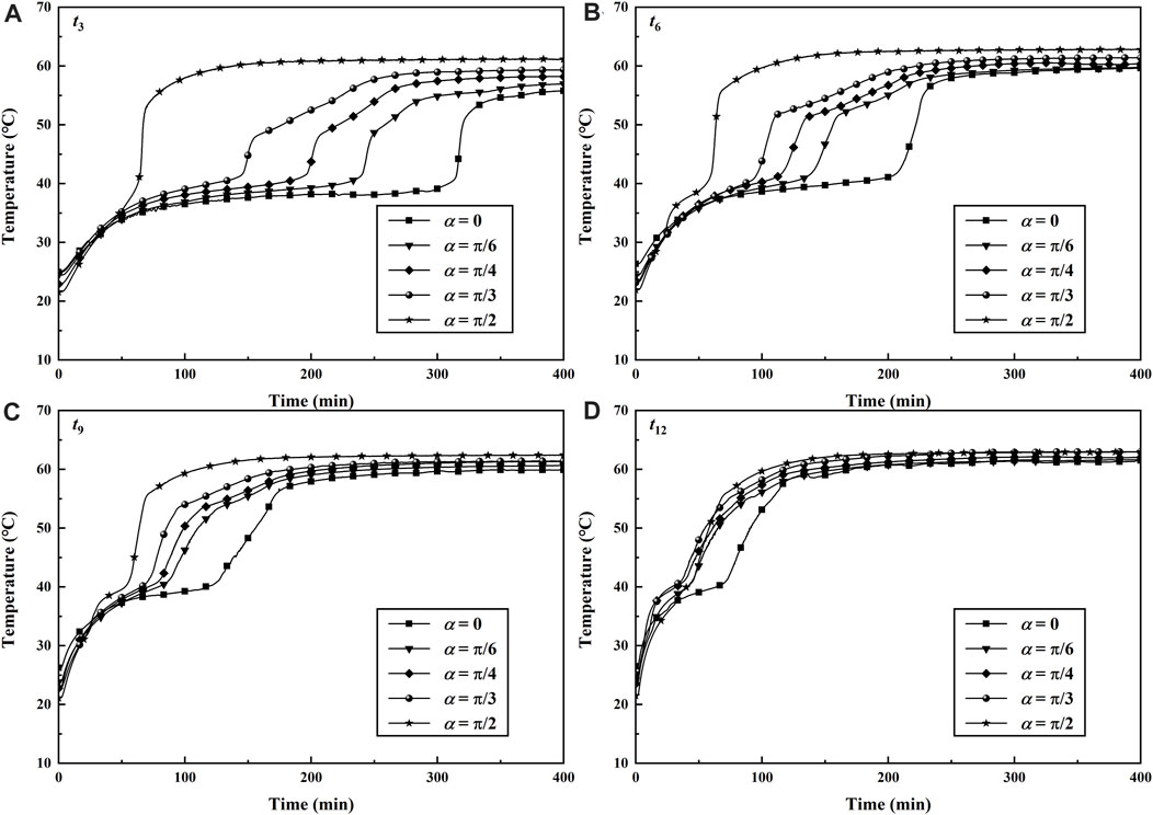
FIGURE 9. Transient temperatures with different inclined angles during the melting process for tin = 63.1°C, qv = 40 L/h.
Conclusion
Experimental investigations of temperature variation with time during the charging process in an inclined shell-and-tube phase-change thermal energy storage unit were carried out. The effects of inlet HTF temperature and flow rate for the case of α = π/4 on the heat transfer characteristics were discussed and analyzed. The results indicated that the heat transfer rate increased with the increase in flow rate, but the flow rate had little effect on the charging process for the case of qv ≥ 40 L/h. The value of temperature at every point mainly was closely related to the location of the PCM domain. It is obvious that the value of temperature at the point nearby the HTF tube or in the upper part was higher than that at other points. The solid–liquid interface presented a concave surface because the heat transfer can be affected not only by conduction in the PCM domain but also by natural convection significantly. The natural convection occurred above the HTF tube, and the strength of convection was restrained and the heat transfer rate below the HTF tube, especially in the bottom region. When the value of HTF inlet temperature increased, the heat transfer rate increased gradually. The time required for the case of tin = 57.9°C was far greater than that for tin = 77.7°C when the PCM averaged temperature attained 50°C. In addition, the effects of inclined angle on the heat transfer rate cannot be negligible. The melting speed of PCM above the HTF tube increased with the increase of inclined angle. For the horizontal case, the bottom wall was heated and the top wall was cooled in this region. Therefore, natural convection plays a significant role in the charging process.
Data Availability Statement
The original contributions presented in the study are included in the article/Supplementary Material; further inquiries can be directed to the corresponding author.
Author Contributionm
KZ: conceptualization, methodology, writing—original draft, and supervision. XH: experimental data, formal analysis, investigation, and writing—original draft. LW: writing—review and editing and supervision. YY: validation and investigation.
Conflict of Interest
The authors declare that the research was conducted in the absence of any commercial or financial relationships that could be construed as a potential conflict of interest.
Publisher’s Note
All claims expressed in this article are solely those of the authors and do not necessarily represent those of their affiliated organizations, or those of the publisher, the editors, and the reviewers. Any product that may be evaluated in this article, or claim that may be made by its manufacturer, is not guaranteed or endorsed by the publisher.
Acknowledgments
The financial support from the Chinese National Natural Science Foundation under Grant No. 51866008 and the Foundation of a Hundred Talents Training Program of Lanzhou Jiaotong University is gratefully acknowledged.
Abbreviations
α, inclined angle of phase-change heat storage unit; tin, inlet temperature of phase-change heat storage unit, °C; tout, the outlet temperature of phase-change heat storage unit, °C; θ, angular position; r, radical position, m; z, axial position, m; L, length of phase-change heat storage unit, m; tf, ambient temperature, °C; g, gravitational acceleration, m/s2; δ, copper pipe wall thickness, m; ri, inner diameter of the copper pipe, m; ro, acrylic tube inner diameter, m; qv, volume flow of HTF, L/h; τ, experimental time, min; ρs, solid density, kg/m3; ρl, liquid density, kg/m3; Cp, specific heat at constant pressure, J/(kg·K); Q, heat storage quantity, kJ; k, thermal conductivity, W/(m·K); μ, dynamic viscosity, kg/(m·s); H, latent heat, kJ/kg; tm, melting temperature, °C; ts, solidification temperature, °C; PCM, phase-change material; HTF, heat transfer fluid.
References
Agyenim, F., Eames, P., and Smyth, M. (2009). A Comparison of Heat Transfer Enhancement in a Medium Temperature Thermal Energy Storage Heat Exchanger Using Fins. Sol. Energy, 83(9), 1509–1520.doi:10.1016/j.solener.2009.04.007
Avci, M., and Yazici, M. Y. (2018). An Experimental Study on Effect of Inclination Angle on the Performance of a PCM-Based Flat-type Heat Sink. Appl. Therm. Eng., 131, 806–814.doi:10.1016/j.applthermaleng.2017.12.069
Kamkari, B., Shokouhmand, H., and Bruno, F. (2014). Experimental Investigation of the Effect of Inclination Angle on Convection-Driven Melting of Phase Change Material in a Rectangular Enclosure. Int. J. Heat Mass Transf., 72, 186–200.doi:10.1016/j.ijheatmasstransfer.2014.01.014
Farid, M. M., Khudhair, A. M., Razack, S., and Al-Hallaj, S. (2004). A Review on Phase Change Energy Storage: Materials and Applications. Energy Convers. Manag., 45(9), 1597–1615.doi:10.1016/j.enconman.2003.09.015
Han, G. S., Ding, H. S., Yun, H., Tong, L. G., and Ding, Y. L. (2017). A Comparative Study on the Performances of Different Shell-And-Tube Type Latent Heat Thermal Energy Storage Units Including the Effects of Natural Convection. Int. Commun. Heat Mass Transf., 88, 228–235.doi:10.1016/j.icheatmasstransfer.2017.09.009
Ji, C., Qin, Z., and Dubey, S., (2018). Simulation on Pcm Melting Enhancement with Double-Fin Length Arrangements in a Rectangular Enclosure Induced by Natural Convection. Int. J. Heat Mass Transf., 127, 255–265. doi:10.1016/j.ijheatmasstransfer.2018.07.118
Jmal, I., and Baccar, M. (2018). Numerical Investigation of PCM Solidification in a Finned Rectangular Heat Exchanger Including Natural Convection. Int. J. Heat Mass Transf., 127, 714–727.doi:10.1016/j.ijheatmasstransfer.2018.08.058
Joneidi, M. H., Hosseini, M. J., Ranjbar, A. A., and Bahrampoury, R. (2017). Experimental Investigation of Phase Change in a Cavity for Varying Heat Flux and Inclination Angles. Exp. Therm. Fluid Sci., 88, 594–607.doi:10.1016/j.expthermflusci.2017.07.017
Kamkari, B., and Groulx, D. (2018). Experimental Investigation of Melting Behaviour of Phase Change Material in Finned Rectangular Enclosures under Different Inclination Angles. Exp. Therm. Fluid Sci., 97, 94–108. doi:10.1016/j.expthermflusci.2018.04.007
Karami, R., and Kamkari, B. (2018). Investigation of the Effect of Inclination Angle on the Melting Enhancement of Phase Change Material in Finned Latent Heat Thermal Storage Units. Appl. Therm. Eng., 146, 45–60.doi:10.1016/j.applthermaleng.2018.09.105
Kothari, R., Sahu, S. K., Kundalwal, S. I., and Sahoo, S. P. (2021).Experimental Investigation of the Effect of Inclination Angle on the Performance of Phase Change Material Based Finned Heat Sink. J. Energy Storage, 37, 102462–102462.doi:10.1016/j.est.2021.102462
Kousha, N., Hosseini, S., Aligoodarz, M. R., Pakrouh, R., and Bahrampoury, R. (2017). Effect of Inclination Angle on the Performance of a Shell and Tube Heat Storage Unit – an Experimental Study. Appl. Therm. Eng., 112, 1497–1509.doi:10.1016/j.applthermaleng.2016.10.203
Mehta, D. S., Solanki, K., Rathod, M. K., and Banerjee, J. (2019). Influence of Orientation on Thermal Performance of Shell and Tube Latent Heat Storage Unit. Appl. Therm. Eng., 157, 113719–113719.doi:10.1016/j.applthermaleng.2019.113719
Pahamli, Y., Hosseini, M. J., Ranjbar, A. A., and Bahrampoury, R. (2017). Effect of Nanoparticle Dispersion and Inclination Angle on Melting of PCM in a Shell and Tube Heat Exchanger. J. Taiwan Inst. Chem. Eng., 81, 316–334.doi:10.1016/j.jtice.2017.09.044
Rehman, T. u., Ali, H. M., Janjua, M. M., Sajjad, U., and Yan, W. M. (2019). A Critical Review on Heat Transfer Augmentation of Phase Change Materials Embedded with Porous Materials/foams. Int. J. Heat Mass Transf., 135, 649–673.doi:10.1016/j.ijheatmasstransfer.2019.02.001
Sathe, T., and Dhoble, A. S. (2019). Thermal Analysis of an Inclined Heat Sink with Finned Pcm Container for Solar Applications. Int. J. Heat Mass Transf., 144, 118679–118679.doi:10.1016/j.ijheatmasstransfer.2019.118679
Sharifi, N., Robak, C. W., Bergman, T. L., and Faghri, A. (2013). Three-dimensional PCM Melting in a Vertical Cylindrical Enclosure Including the Effects of Tilting. Int. J. Heat Mass Transf., 65, 798–806.doi:10.1016/j.ijheatmasstransfer.2013.06.070
Sharma, A., Chauhan, R., Kalliolu, M. A., Chinnasamy, V., and Singh, T. (2020). A Review of Phase Change Materials (PCMs) for Thermal Storage in Solar Air Heating Systems. Mater. Today Proc., 44, 4357–4363.doi:10.1016/j.matpr.2020.10.560
Siyabi, I. A., Khanna, S., Mallick, T., and Sundaram, S. (2019). An Experimental and Numerical Study on the Effect of Inclination Angle of Phase Change Materials Thermal Energy Storage System. J. Energy Storage, 23, 57–68.doi:10.1016/j.est.2019.03.010
Wooszyn, J., Szopa, K., and Czerwiński, G. (2021). Enhanced Heat Transfer in a PCM Shell-And-Tube Thermal Energy Storage System. Appl. Therm. Eng., 196(17), 117332–117332.doi:10.1016/j.applthermaleng.2021.117332
Xie, J., Choo, K. F., Xiang, J., and Lee, H. M. (2019). Characterization of Natural Convection in a Pcm-Based Heat Sink with Novel Conductive Structures. Int. Commun. Heat Mass Transf., 108, 104306–104306.doi:10.1016/j.icheatmasstransfer.2019.104306
Keywords: phase-change materials, inclined angle, heat transfer rate, thermal energy storage, changing process
Citation: Zhang K, He X, Wang L and Yu Y (2022) Experimental Study on the Heat Transfer Characteristics of an Inclined Shell-and-Tube Phase-Change Thermal Energy Storage Unit. Front. Energy Res. 10:881970. doi: 10.3389/fenrg.2022.881970
Received: 23 February 2022; Accepted: 20 April 2022;
Published: 23 May 2022.
Edited by:
Xiaoliang Zeng, Chinese Academy of Sciences (CAS), ChinaReviewed by:
Cong Qi, China University of Mining and Technology, ChinaLong Zhang, Beijing Institute of Technology, China
Copyright © 2022 Zhang, He, Wang and Yu. This is an open-access article distributed under the terms of the Creative Commons Attribution License (CC BY). The use, distribution or reproduction in other forums is permitted, provided the original author(s) and the copyright owner(s) are credited and that the original publication in this journal is cited, in accordance with accepted academic practice. No use, distribution or reproduction is permitted which does not comply with these terms.
*Correspondence: Kun Zhang, emhhbmdrdW41MjAxNUAxNjMuY29t