 Chen Shi
 Jianfeng Zhao*
- School of Electrical Engineering, Southeast University, Nanjing, China
The grid-connected inverter system may be unstable when connected to a weak grid, and installing an active damper as a virtual resistor at the PCC is convenient for stabilizing the system. This article proposes a passivity enhancement strategy for the grid-connected inverter system via the adaptive active damper. Furthermore, the admittances of the grid-connected inverter system with the active damper are derived, and the real parts of the admittances of the whole system have been calculated. And the admittance measurement results obtained by the frequency scanning method approximately match the theoretical results. Additionally, the virtual resistor’s stability region is discussed, the bandwidth of the phase-locked loop is recommended, ensuring the stabilizing effect of the active damper under the weak grid. And the online resonance frequency detection algorithm guarantees the passivity enhancement of the active damper when grid impedance changes. Finally, controller hardware-in-the-loop tests validate the theoretical analysis of passivity enhancement based on the active damper.
1 Introduction
The grid-connected inverter (GCI) with the LCL filter is an essential interface between the distributed renewable energy and the utility grid (Li et al., 2017; Wang and Blaabjerg, 2019). However, the LCL filter is a third-order filter with inherent resonance characteristics, and the interaction between the grid impedance and the converters may trigger high-frequency oscillations (Akhavan et al., 2020; Kang, 2020; Chen et al., 2021). To mitigate harmonic oscillations and improve system stability, the active damper is proposed in Wang et al. (2014) to be installed at the point of common coupling (PCC).
Previous work investigates many topologies suitable for the active damper to achieve impedance shaping and resonance suppression. In Wang et al. (2014a) and Wang et al. (2014b), the L filter is adopted for the active damper. In Cheng et al. (2020) and Jia et al. (2018), the active damper is implemented with the LCL filter for lower costs and size. In Zhou et al. (2018), the active damper adopts the LC filter since the voltage source converter is easier to virtualize smaller harmonic impedance than the current source converter. In Bai et al. (2017), Wang et al. (2015), and Bai et al. (2016), active dampers are equipped with the series LC filter, reducing their power ratings significantly. In Zhao et al. (2019) and Lu et al. (2016), instead of paralleling at the PCC, the adaptive stabilizer is connected in series to reshape the grid impedance. In Ni et al. (2021), a unified active damper combining a parallel and serial converter is proposed to reshape the equivalent impedance and enhance the stability of the GCI system. In Guo et al. (2019) and Lin and Ruan (2019), instead of installing an extra converter at the PCC, the active damper is achieved by adding a damping branch on the control algorithm of the existing grid-connected inverter, requiring an upgrade in the control program’s existing inverters.
Existing research also focuses on the active damper’s control strategy, especially on virtual impedance emulation and resonance detection. In Jia et al. (2018), the variable virtual resistor-based adaptive resonance suppression control strategy of the active damper is proposed. In Li et al. (2020), the lowest value of the virtual resistor is designed to avoid the over-modulation problem. In Cheng et al. (2020), an RL-type active damper is proposed to cope with the wideband oscillation, avoiding the instability caused by the system parameter variations. In Zhou et al. (2017), an active capacitor converter is proposed to shape the equivalent impedance at the PCC by emulating paralleled capacitor. However, the virtual capacitor requires a differential operation, inevitably amplifying the computational noises. In Jin et al. (2020), a cascaded SOGI-FLL with pre-filter is adopted to detect the unstable frequency region in real-time.
Both impedance-based and passivity-based stability criteria can be utilized to analyze the stability of the GCI system (Harnefors et al., 2016; Sun, 2011; Xiong et al., 2020; Wu et al., 2020; Liao et al., 2020). For the paralleled inverter system, the passivity-based criterion is more intuitive since it is possible to analyze the frequency band where the instability occurs, so the parameters of the whole system can be designed quantitatively (Han et al., 2022; Qian et al., 2020). Noting that the passivity is a sufficient yet unnecessary condition to ensure the system is stable, the relatively conservative analysis result can provide a large stability margin of the system (Yoon et al., 2016).
This article is organized as follows. Section 2 introduces the GCI system with the active damper. In Section 3, the admittances of the grid-connected inverter system with the active damper are modeled and measured by the frequency scanning method. The tradeoff design of the active damper is achieved in Section 4. The passivity enhancement result by the adaptive active damper is presented in Section 5. The controller hardware-in-the-loop (CHIL) tests results are presented in Section 6. Conclusions are drawn in Section 7.
2 System Description
2.1 Grid-Connected Inverter System With the Active Damper
As shown in Figure 1, this article analyses a GCI system with the active damper under the weak grid. The active damper is simulated as a resistor connected in parallel at the PCC, damping the resonance between the grid-connected inverter and the grid, stabilizing the GCI system (Zhang et al., 2016). The LCL filter of the GCI comprises the inverter-side inductor Lfi, the filter capacitor Cfi, and the grid-side inductor Lgi. For simplicity, its DC-link voltage Vdci is assumed to be constant. The second-order generalized integrator-based phase-locked loop (SOGI-PLL) is adopted for real-time grid synchronization. For the active damper, the resonant component upcc_r extracted by the adaptive resonance detection method is divided by the virtual resistor value Re to obtain the harmonic current reference iAD_r_ref. The active damper’s output current, iAD, is tracked through the current controller Gca, where the PR controller is utilized. The DC voltage controller Gdca maintains the DC side voltage constant. The Hica is the capacitor current feedback coefficient.
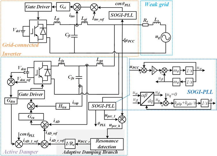
FIGURE 1. Grid-connected inverter system with the active damper under weak grid.
3 Admittance Modeling of Grid-Connected Inverter System With the Active Damper
3.1 Admittance Modeling of the Grid-Connected Inverter
The mathematical model of the GCI could be derived as Figure 2A. The grid-connected inverter contains two control loops, the path of the current control loop is from the iinv_ref to iinv, while the path of the phase-locked loop is from the upcc to Iinv_ref. The simultaneous sampling mode is adopted in this study. Hence, the sampling frequency equals the switching frequency. The time delay is 1.5 sampling period, so the Gdi = e−1.5sTswi. Kpwm represents the gain of the inverter bridge. TPLL stands for the transfer function model of the phase-locked loop from the upcc to cosθ. Τhe HiCi is the capacitor current feedback coefficient. The Gci is the current controller and could be expressed as Eq. 1.
By executing a similar transformation in Wang et al. (2010) and Yang et al. (2014), Figure 2A can be transformed into and equivalent parts can be expressed as Eqs 2,3.
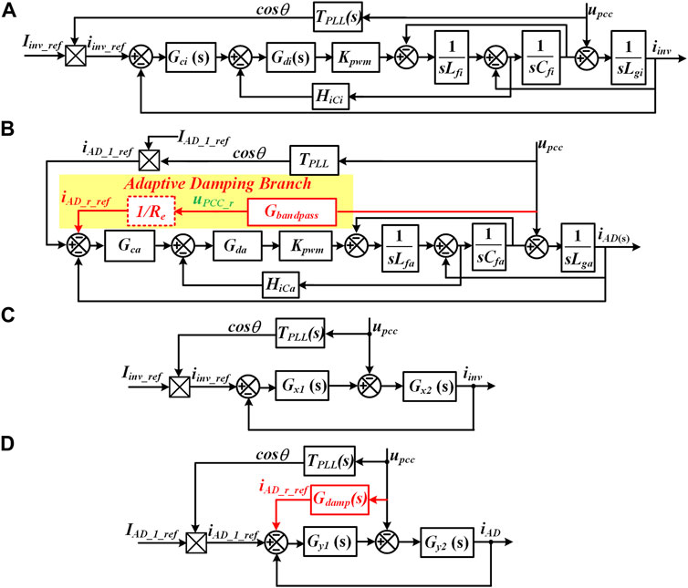
FIGURE 2. Mathematical models of the GCI and active damper and corresponding simplified models. (A) Mathematical model of the GCI. (B) Mathematical model of the active damper. (C) Simplified model of the GCI. (D) Simplified model of the active damper.
According to Figure 2C, the output current of the grid-connected inverter can be derived as
where YPLLi and Yconi are the equivalent admittances of the PLL and current loop and can be expressed as
In which, Δi is the characteristic equation of the grid-connected inverter and can be derived as
In Zhang et al. (2015b), Chen et al. (2017), and Xu et al. (2019), it has been proven that the single-phase SOGI-PLL shown in Figure 1 has the small-signal transfer function from upcc to the cosθ can be expressed as Eq. 8. In TPLL, the Um stands for the amplitude of upcc, and ω0 is the fundamental frequency, the GPI denotes the PI controller.
In which the GOSG−α stands for the transfer function from upcc to uα and can be expressed as Eq. 9.
3.2 Admittance Modeling of the Active Damper
As shown in Figure 2B, the active damper has one more damping branch to imitate the virtual resistor for harmonic resonance suppression. Likewise, Figure 2B can be simplified as Figure 2D. The expressions of the admittances of the active damper could be derived as Eqs 10–13.
The characteristic equation can be expressed as Eq. 14.
The current loop of the active damper could be derived as
The damping branch of the active damper could be expressed as Eq. 16, where Re is the virtual resistor. As for the bandpass filter shown in Eq. 17, the quality factor Q is chosen as 2.5 to ensure a wide range of resonance suppression.
3.3 Admittance Shaping Strategy Based on Active Damper
As shown in Figure 3, after installing the active damper at the PCC, the inverter-side admittance could be reshaped as Ysum. The passivity of the whole system can be guaranteed when the reshaped admittance Ysum is passive, that is −90°≤∠Ysum (jω) ≤90° in the whole frequency range (Ma et al., 2020; Zhao et al., 2021).
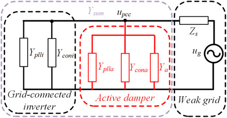
FIGURE 3. Reshaped admittance of GCI system with the active damper under weak grid.
4 Tradeoff Design of the Active Damper
4.1 Critical Frequencies Design of the Active Damper
To ensure the harmonic resonance suppression capability of the active damper, related critical frequencies should be appropriately designed. As shown in Eq. 18, the LCL resonance frequency of the active damper, the fresa should be lower than fswa/6 to guarantee stability under weak grid conditions according to Pan et al. (2015). The cutoff frequency of the current loop fca should be higher than the potential maximum resonance frequency of the grid-connected inverters fres_inv_max to guarantee the resonances suppression effect. In this study, the fres_inv_max is chosen as 2 kHz. Also, fca should be lower than fswa/10 to avoid the influence of switching harmonics on the current loop. The fca can be set at around 0.3 times of the LCL filter resonance frequency fresa to ensure enough phase margin (Tang et al., 2012, Wang et al., 2014c).
4.2 Electrical Parameters Design of the Active Damper
The implementation cost of the active damper is directly related to its power rating. It is determined by the pre-defined smallest virtual resistor it intends to imitate, namely the Re_min, and the maximum value of the ratio of the target resonant component to be damped to the fundamental component of the PCC voltage and, namely, the λr_max. The apparent nominal power of the active damper, the SAD could be calculated as Eq. 19.
Assuming the Re_min = 5Ω, λr_max = 10%, and Vn = 220V, it is calculated that SAD_min ≈1 kVA from Eq. 19. The nominal current IADn of the active damper could be derived as Eq. 20 and could be calculated as 4.4A.
The expression of the filter capacitor could be derived as Eq. 21, in which the λC is the ratio of the reactive power introduced by the filter capacitor to the power rating of the active damper.
Assuming λc = 0.05, the value of Cfa is limited to less than 3.2 μF to reduce the current conduction losses of the IGBT. In this study, the Cfa is chosen as 2 μF. Considering the constraint of (Eq. 18), the Lfa is chosen as 0.8 mH, the Lga is selected as 0.5 mH, and the fresa is 6416 Hz according to Eq. 22.
4.3 Current Loop Design of the Active Damper
In Bai et al. (2017), it has been verified that resonance suppression can still be achieved even if the active damper only adopts the proportional controller. According to Ruan et al. (2017), the capacitor branch could be approximated to open circuit when the frequency is equal to or lower than the fca, so Eq. 15 could be simplified as
Since the resonant part has little effect on the high-frequency components, the current controller Gca can be approximated to Kpa at fca and the frequencies are higher than fca, that is |Gca(j2πfca)| = 1. Hence the proportional coefficient could be yielded (24), considering that the current loop gain has unit magnitude at fca (Parker et al., 2014), that is |TAD(j2πfca)| = 1.
To ensure the effective damping effect of the potential resonances, let fca = fres_inv_max, and it could be calculated that Kpa = 16 according to Eqs 18–24. To increase the phase margin, the Kra of the PR controller can be chosen lower.
4.4 PLL Design of the Active Damper
Under weak grid conditions, a relatively low bandwidth of PLL could guarantee the stability of the GCI system (Zou et al., 2021). According to Han et al. (2022) and Zhang et al. (2015a), considering PLL bandwidth, the PI parameters of PLL could be calculated as
According to Eqs 8, 9, 12, 25, 26, when the parameters of Table 2, when ξ = 0.707, IAD_1_ref = 10A, the real part of the output admittance of the SOGI-PLL of the active damper versus frequency and bandwidth of the SOGI-PLL can be depicted in Figure 4.
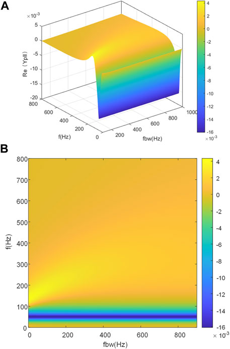
FIGURE 4. Real part of Ypll versus fbw and f. (A) Main view. (B) Top view.
Figure 4 indicates that as the non-passive region enlarges, the bandwidth of the SOGI-PLL increases. In this study, the bandwidth of the PLL is selected as 100 Hz to ensure the passivity and stability of the active damper at the low-frequency range.
5 Passivity Enhancement Strategy Based on the Active Damper
5.1 Relationship Between the Passivity and Stability
According to Chen et al. (2020) and Cheng et al. (2020), if the reshaped admittance Ysum shown in Figure 3 has a positive real part in the whole frequency range, the GCI system under the weak grid is passive and stable. With parameters of Tables 1, 2, the theoretical passivity improvement provided by an active damper is shown in Figure 5A. After admittance shaping, the Ysum has a positive real part, except for fundamental frequency, indicating high-frequency harmonic resonances can be well suppressed. As for the non-passive region introduced by the PLL at around 50 Hz, it can hardly be avoided without reducing the rated power of the GCI since the PLL has a negative impact on the passivity (Harnefors et al., 2007; Harnefors et al., 2016). It should be noted that Ycona can also compensate for the non-passive region, contributing to the stability of the GCI system.
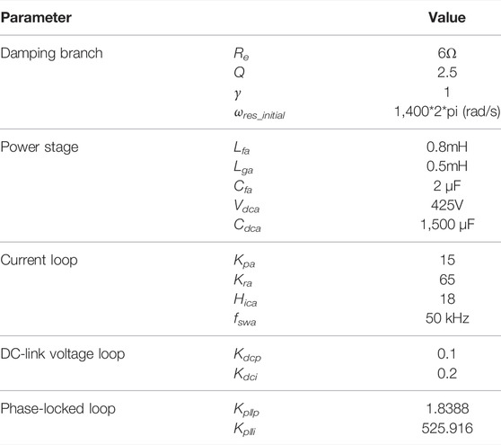
TABLE 1. Electrical and control parameter of the active damper.
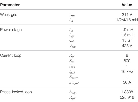
TABLE 2. Parameters of the grid-connected inverter system.
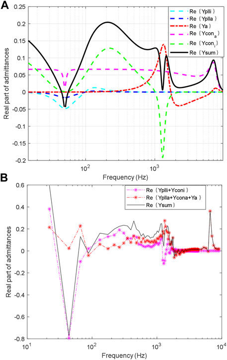
FIGURE 5. Real part of admittances versus frequency of GCI system with the active damper. (A) Theoretical analysis result. (B) Frequency scanning result.
The measured real parts of admittances of the grid-connected inverter and the active damper are shown in Figure 5B. Measurement of admittances of the GCI system with the active damper is carried out via the impedance analysis toolbox in the PLECS platform. The output admittances can be calculated by injecting the perturbation current at the PCC and measuring the response voltage signal in the time domain. Comparing Figures 5A,B with, the real parts of admittances of the grid-connected inverter and the active damper given by mathematical models roughly matched with corresponding measured results, proving the correctness of the theoretical analysis. Therefore, the analytical models can perform the passivity-based stability investigations of the GCI system with the active damper. As shown in the frequency sweeping results, the passivity of the GCI system is greatly enhanced by the active damper. The non-passive region of the grid-connected inverter has been dramatically compensated, and the risk of high-frequency oscillations has been reduced.
5.2 Stability Region-Based Damping Branch Design
To avoid overmodulation, the lowest limit of the virtual resistor Re could be calculated as Re ≥ 4.46 according to Eq. 27 and parameters of Table 1.
As the effect of PLL on the passivity could be neglected in the high-frequency range according to Figure 5, the reshaped inverter-side admittance Ysum could be approximated to {Ya + Yconi + Ycona}. So high-frequency non-passive region is mainly related to the real part of {Ya + Yconi + Ycona}, so the admittance of the PLL could be ignored when analyzing the high-frequency oscillations.
According to Eqs. 11–13 and parameters in Table 1, the real part of the equivalent admittances of the active damper versus Re and frequency is shown in Figure 6. When the Re is too small, the Re{Ya + Yconi + Ycona} is negative at frequencies higher than the objective frequency band, implying the risk of high-frequency oscillation. So a too-small Re enhances the passivity of the objective frequency band at the cost of reducing the passivity of the GCI system at higher frequencies.
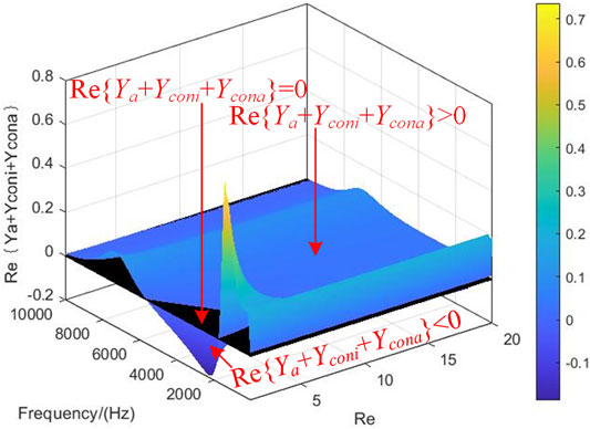
FIGURE 6. Real part of {Ya + Ycona + Yconi} versus Re and frequency.
The selection of the Re is a tradeoff between the passivity enhancement of the grid-connected inverter and the active damper itself. And in this study, Re is chosen as 6Ω.
5.3 SOGI-FLL-Based Adaptive Resonance Detection Method
The SOGI-FLL-based resonance detection algorithm in Figure 7 can trace the resonant frequency in real-time (Cao et al., 2018; Jin et al., 2020). The SOGI module in SOGI-FLL also serves as the bandpass filter corresponding to Eq. 17. Before the system starts up, the initial value of ωres, the ωres_initial should be set. The saturation of the integrator outputting ωres is set to prevent the SOGI-FLL from tracking low order or switching harmonics. The ωres is limited to 2π*1,000 to 2π*2000 (rad/s), and the γ is set relatively small for accurate resonance frequency detection.
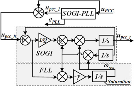
FIGURE 7. Adaptive resonance detection based on SOGI-FLL.
6 Verifications
6.1 CHIL Platform Setup
The CHIL system is essential for verifying controllers and implementing algorithms, especially under risky test conditions (Bontemps et al., 2021). This study implemented the grid-connected inverter and the active damper algorithms in the Ti 28379D MCU controller with a sampling time of 20 μs. The hardware system was emulated in the RT-BOX 1, where the simulation time step is 3 µs. Due to the hardware limitations, only one grid-connected inverter is emulated in the CHIL test. The switch “SW” is employed to carry out the plug-in and removal test of the active damper. It should be noted that “SW” is paralleled with a bypass resistor “Rsw” with the value of 10 kΩ since the ideal switch can lead to numerical error in the CHIL test.
The schematic diagram and setup of the CHIL test are shown in Figure 8, and the DSP controller is connected to the RT-BOX via the interface PCB board. The switch “SW” shown in Figure 8 is employed to achieve the active damper’s plug-in and removal.
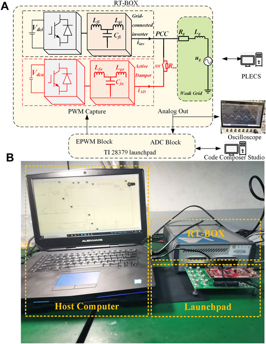
FIGURE 8. Schematic diagram and setup of the CHIL test. (A) Schematic diagram of the CHIL test. (B) Setup of the CHIL test.
The control and electrical parameters of the grid-connected inverter system and the active damper are shown in Table 1.
The control and electrical parameters of the GCI system under the weak grid are shown in Table 2.
6.2 Dynamic performance of plugging in and removing the active damper.
As shown in Figure 9A, when the switch is open, the phenomenon of resonance occurs, and the whole system becomes unstable without the active damper. When the “SW” is closed, the resonant components of both PCC voltage and grid-current are quickly attenuated, proving the passivity enhancement effect of the active damper. The active damper absorbs the harmonic resonance components and returns the power to the grid at the fundamental frequency. The FFT analysis of the PCC voltage when the resonance occurs is shown in Figure 9B. The resonance frequency is roughly 1.1 kHz, which equals to the resonance frequency of the grid-connected inverter when Ls = 4 mH, validating the analysis in Figure 5.
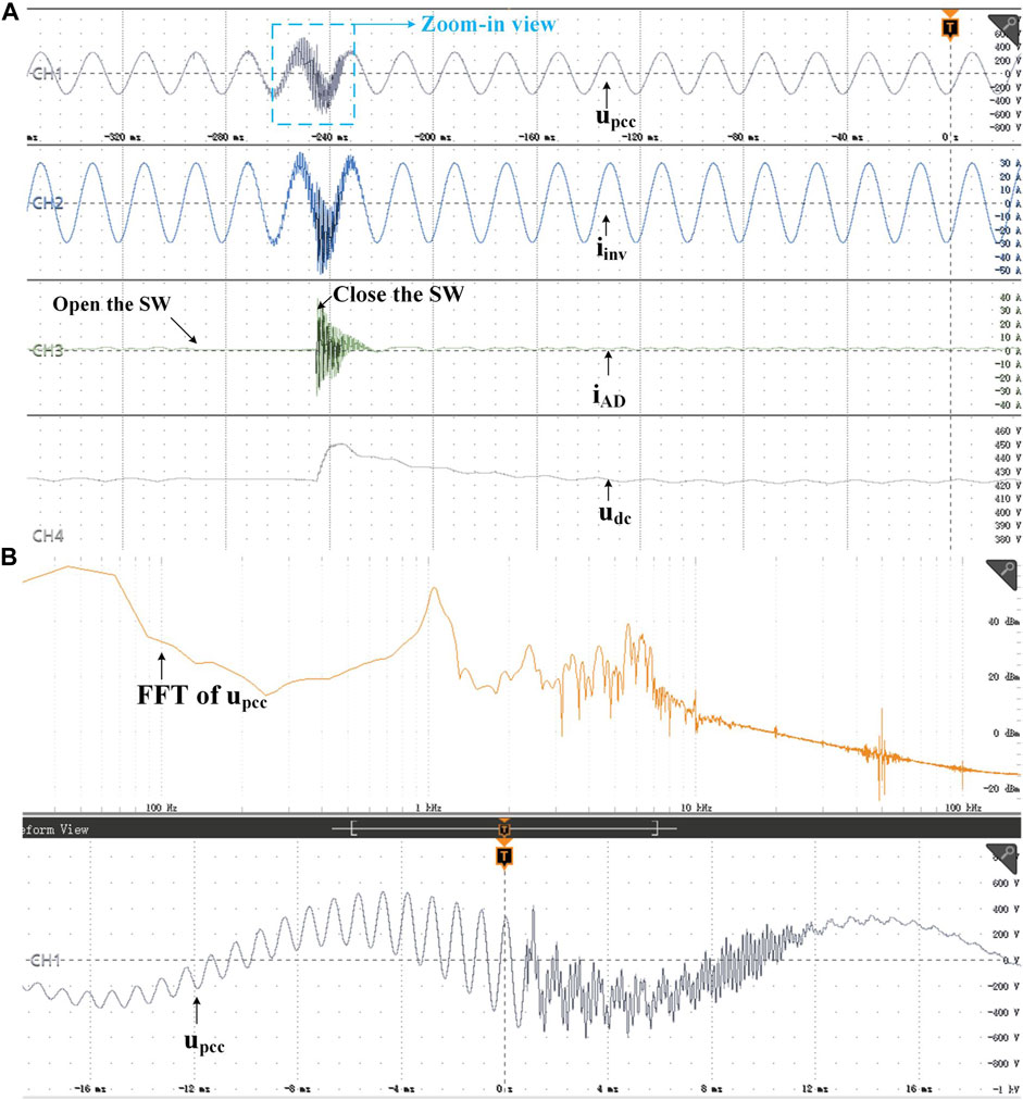
FIGURE 9. Dynamic performance of plugging in and removing the active damper by opening and closing the switch. (A) Overall view. (B) Zoom-in view and corresponding FFT analysis.
6.3 Adaptive Resonance Detection Effect
The dynamic resonance frequency estimation effect of the SOGI-FLL is shown in Figure 10, where the “SW” is open. When the grid-side inductance suddenly decreases from 4 mH to 2 mH, the detected resonance frequency by the SOGI-FLL increases accordingly, proved by the FFT analysis.
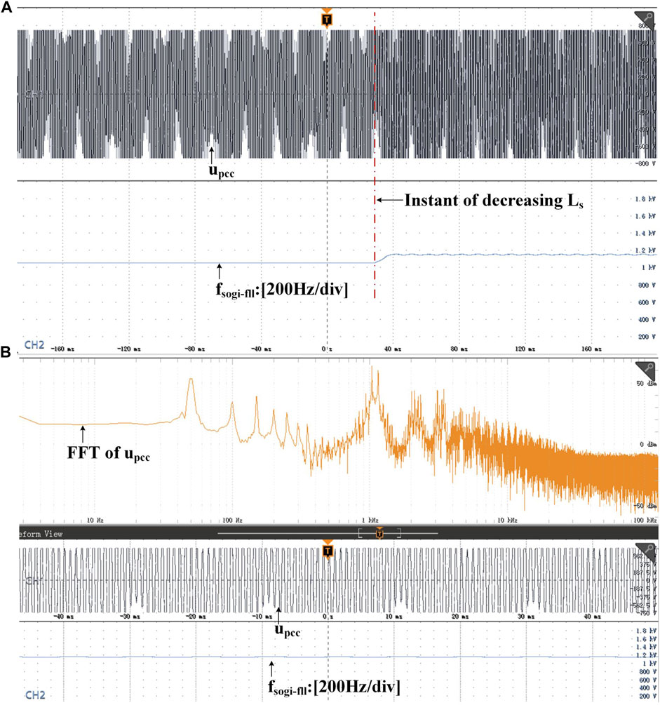
FIGURE 10. Resonance detection of the SOGI-FLL. (A) Dynamic waveform when Ls decreases. (B) FFT analysis and resonance frequency detection result of the upcc in steady-state.
6.4 Stability-region of the virtual resistor
Figure 11A shows the dynamic performance of the active damper when Re changes from 6 to 1.5 Ω when Ls = 2 mH, indicating that a too low Re can trigger the harmonic resonance of the active damper itself, resulting in instability. The FFT analysis shown in Figure 11B shows a resonance peak at around 4.5 kHz, the resonance frequency of the LCL filter of the active damper influenced by the Ls. This indicates that a too-small virtual resistor can bring a new non-passive region, verifying the theoretical analysis shown in Figure 6.
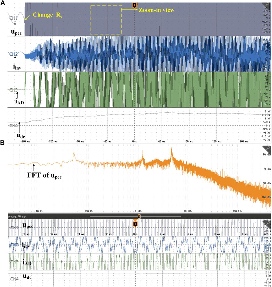
FIGURE 11. Dynamic performance and corresponding FFT when the Re of the active damper sudden decreases. (A) Dynamic waveform from stability to instability (B) Steady-state waveform and FFT analysis of PCC voltage when Re = 1.5Ω.
6.5 Dynamic Performance of Active Damper when Grid Impedance Sudden Changes
Figure 12 shows the dynamic performance of the GCI system with the active damper when the grid impedance suddenly changes from 1 mH to 16 mH. The GCI system with the active damper remains stable after the impedance increases, and the transient process is relatively short.
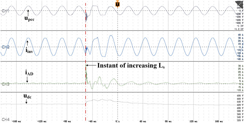
FIGURE 12. Dynamic performance of the GCI system with the active damper when the grid inductance suddenly increases.
6.6 Effect of Bandwidths of PLL on the Stability of GCI System.
Comparisons of the start-up process of the active damper with different bandwidths of the PLL are shown in Figure 13. Ls is chosen as 16 mH, corresponding to SCR = 2.06. When an unnecessarily high bandwidth of PLL of the active damper is adopted, the system will likely become unstable since the non-passive region enlarges as PLL bandwidth increases, verifying the theoretical analysis shown in Figure 4.

FIGURE 13. Waveforms of grid-connected inverter system with active damper with different SOGI-PLL bandwidth fBW. (A) fBW = 1000 Hz. (B) fBW = 100 Hz.
7 Conclusion
This article proposes a passivity enhancement strategy of the grid-connected inverter system via the adaptive active damper. The mathematical models of admittances of the GCI system with the active damper under the weak grid are derived. The admittances of the grid-connected inverter and the active damper have been measured by the frequency scanning method, verifying previous mathematical models. The tradeoff design of the active damper is carried out to achieve high conductance for wideband damping, and the bandwidth selection of the PLL of the active damper is recommended. The online resonance frequency detection is achieved, ensuring the stabilizing effect of the active damper under different grid impedances. The stability region of the virtual resistor is discussed to avoid overmodulation and the high-frequency oscillations of the active damper itself. Finally, the CHIL tests verified the theoretical analyses, proving the passivity enhancement effect of the grid-connected inverter system by the active damper.
Data Availability Statement
The raw data supporting the conclusion of this article will be made available by the authors, without undue reservation.
Author Contributions
CS contributed to the conception and design of the proposed strategy. All authors wrote and edited the manuscript.
Funding
This work was supported by the National Natural Science Foundation of China (51877042).
Conflict of Interest
The authors declare that the research was conducted in the absence of any commercial or financial relationships that could be construed as a potential conflict of interest.
Publisher’s Note
All claims expressed in this article are solely those of the authors and do not necessarily represent those of their affiliated organizations, or those of the publisher, the editors, and the reviewers. Any product that may be evaluated in this article, or claim that may be made by its manufacturer, is not guaranteed or endorsed by the publisher.
Acknowledgments
The authors gratefully acknowledge the support of the National Natural Science Foundation of China (51877042).
References
Akhavan, A., Mohammadi, H. R., and Vasquez, J. C. (2020). Passivity-Based Design of Plug-And-Play Current-Controlled Grid-Connected Inverters. IEEE Trans. Power Electro. 35 (2), 2135–2150. doi:10.1109/tpel.2019.2920843
Bai, H., Wang, X., and Blaabjerg, F. (2016). “Passivity Enhancement by Series LC Filtered Active Damper with Zero Current Reference,” in 2016 IEEE 8th International Power Electronics and Motion Control Conference (IPEMC-ECCE Asia), Hefei, China, May 22–26, 2016, 2937–2944.
Bai, H., Wang, X., Loh, C., and Blaabjerg, F. (2017). Passivity Enhancement of Grid-Tied Converters by Series LC-Filtered Active Damper. IEEE Trans. Ind. Electro. 64 (1), 369–379. doi:10.1109/tie.2016.2562604
Bontemps, P., Milovanovic, S., and Dujic, D. (2021). Distributed Real-Time Model of the M3C for HIL Systems Using Small-Scale Simulators. IEEE Open J. Power Electro., 2603–2613. doi:10.1109/ojpel.2021.3130996
Cao, W., Fan, D., Liu, K., Zhao, J., Ruan, L., and Wu, X. (2018). “Resonance Detection Strategy for Multiple Grid-Connected Inverters-Based System Using Cascaded Second-Order Generalized Integrator,” in 2018 International Power Electronics Conference (IPEC-Niigata 2018 -ECCE Asia), IEEJ Industry Application Society, Niigata, Japan, May 20–24, 2018, 3010–3014. doi:10.23919/ipec.2018.8507445
Chen, W., Zhang, Y., Cheng, L., Tu, Y., Cai, Y., and Liu, J. (2021). “An Accurate Resonant Frequency Design Method Considering Digital Control Delay in Grid-Connected Converters,” in 2021 IEEE 12th Energy Conversion Congress & Exposition - Asia (ECCE-Asia), Singapore, May 24–27, 2021, 1771–1776. doi:10.1109/ecce-asia49820.2021.9479024
Chen, W., Zhao, J., Liu, K., and Cao, W. (2020). Passivity Enhancement for LCL-Filtered Grid-Connected Inverters Using the Dominant-Admittance-Based Controller. IET Power Electro. 13 (18), 4140–4149. doi:10.1049/iet-pel.2020.0481
Chen, X., Zhang, Y., Wang, S., Chen, J., and Gong, C. (2017). Impedance-Phased Dynamic Control Method for Grid-Connected Inverters in a Weak Grid. IEEE Trans. Power Electro. 32 (1), 274–283. doi:10.1109/tpel.2016.2533563
Cheng, L., Liu, Z., Liu, J., and Tu, Y. (2020). “An RL-type Active Damper for Stabilizing Wide Band Oscillations in Grid-Tied Inverter Systems,” in 2020 IEEE Energy Conversion Congress and Exposition (ECCE), Detroit, MI, October 11–15, 2020, 1686–1693.
Guo, Y., Chen, L., Lu, X., Wang, J., Zheng, T., and Mei, S. (2019). Region-Based Stability Analysis for Active Dampers in AC Microgrids. IEEE Trans. Industry Appl. 55 (6), 7671–7682. doi:10.1109/tia.2019.2913819
Han, Y., Yang, M., Yang, P., Xu, L., and Blaabjerg, F. (2022). Passivity-based Stability Analysis of Parallel Single-phase Inverters with Hybrid Reference Frame Control Considering PLL Effect. Int. J. Electr. Power Energ. Syst. 135, 107473. doi:10.1016/j.ijepes.2021.107473
Harnefors, L., Bongiorno, M., and Lundberg, S. (2007). Input-Admittance Calculation and Shaping for Controlled Voltage-Source Converters. IEEE Trans. Ind. Electro. 54 (6), 3323–3334. doi:10.1109/tie.2007.904022
Harnefors, L., Wang, X., Yepes, A., and Blaabjerg, F. (2016). Passivity-Based Stability Assessment of Grid-Connected VSCs - an Overview. IEEE J. Emerging Selected Top. Power Electro., 4116–4125. doi:10.1109/jestpe.2015.2490549
Jia, L., Ruan, X., Zhao, W., Lin, Z., and Wang, X. (2018). An Adaptive Active Damper for Improving the Stability of Grid-Connected Inverters under Weak Grid. IEEE Trans. Power Electro. 33 (11), 9561–9574. doi:10.1109/tpel.2018.2793242
Jin, Q., Yao, Z., and Guo, M. (2020). “Stability Improvement for Multi-Inverter System Based on Active Damper with Modified Resonance Detection Method,” in 2020 4th International Conference on HVDC (HVDC), 326–331. doi:10.1109/hvdc50696.2020.9292770
Kang, H. (2020). Research on Resonance Instability Suppression Strategy for the Multi-Inverters Grid-Connected System Based on Reshaping of Global Admittance at PCC. Nanjing: Southeast University.
Li, F., Liu, Y., Xu, K., Ma, M., Zhang, X., and Wang, L. (2020). A Virtual Resistor Design Method Based on Voltage Harmonic Amplification Factor for Active Damper Used in DFIG System. Energ. Rep. 6, 6572–6579. doi:10.1016/j.egyr.2020.11.187
Li, X., Fang, J., Tang, Y., and Wu, X. (2017). Robust Design of LCL Filters for Single-Current- Loop Controlled Grid-Connected Power Converters with Unit PCC Voltage Feedforward. IEEE J. Emerging Selected Top. Power Electro. 1
Liao, Y., Wang, X., and Blaabjerg, F. (2020). Passivity-Based Analysis and Design of Linear Voltage Controllers for Voltage-Source Converters. IEEE Open J. Ind. Electro. Soc., 1114–1126. doi:10.1109/ojies.2020.3001406
Lin, Z., and Ruan, X. (2019). “A Three-phase Adaptive Active Damper for Improving the Stability of Grid-Connected Inverters under Weak Grid,” in 2019 IEEE Applied Power Electronics Conference and Exposition (APEC), Anaheim, CA, March 17–21, 2019, 1084–1089.
Lu, D., Wang, X., Bai, H., and Blaabjerg, F. (2016). “A Series Active Damper with Closed-Loop Control for Stabilizing Single-phase Power-Electronics-Based Power System,” in 2016 IEEE Energy Conversion Congress and Exposition (ECCE), Milwaukee, WI, September 18–22, 2016, 1–7.
Ma, Y., Xu, L., Wang, X., He, Y., Ruan, X., and Liu, F. (2020). “Passivity-based Design of Capacitor-Current-Feedback Active Damping for LCL-Filtered Inverter Considering Computation Delay Reduction,” in 2020 IEEE 11th International Symposium on Power Electronics for Distributed Generation Systems (PEDG), Dubrovnik, Croatia, September 28–October 1, 2020, 364–369. doi:10.1109/pedg48541.2020.9244450
Ni, Z., Cheng, Y., Xu, J., and Cheng, H. (2021). “An Adaptive Series Active Damper for Stabilizing Grid-Connected System under Weak Grid,” in 2021 4th International Conference on Energy, Electrical and Power Engineering, Chongqing, China, April 23–25, 2021 (Chongqing, China: IEE), 581–586. doi:10.1109/ceepe51765.2021.9475704
Pan, D., Ruan, X., Bao, C., Li, W., and Wang, X. (2015). Optimised Controller Design for LCL -Type Grid-Connected Inverter to Achieve High Robustness against Grid-Impedance Variation. IEEE Trans. Ind. Electro. 62 (3), 621537.
Parker, S., Mcgrath, B., and Holmes, G. (2014). Regions of Active Damping Control for LCL Filters", Industry Applications. IEEE Transactions on, 50424.
Qian, Q., Xie, S., Xu, J., Bian, S., and Zhong, N. (2020). Passivity-based Output Admittance Shaping of the Converter-Side Current-Controlled Grid-Tied Inverter to Improve the Robustness to the Grid Impedance. IET Power Electro. 13 (10), 131956. doi:10.1049/iet-pel.2019.0770
Ruan, X., Wang, X., Pan, D., Yang, D., Li, W., and Bao, C. (2017). Control Techniques for LCL-type Grid-Connected Inverters.
Sun, J. (2011). Impedance-Based Stability Criterion for Grid-Connected Inverters. IEEE Trans. Power Electro. 26 (11), 3075–3078. doi:10.1109/tpel.2011.2136439
Tang, Y., Loh, P. C., Wang, P., Choo, F. H., Gao, F., and Blaabjerg, F. (2012). Generalized Design of High Performance Shunt Active Power Filter with Output LCL Filter. IEEE Trans. Ind. Electro. 59 (3), 1443–1452. doi:10.1109/tie.2011.2167117
Wang, X., Blaabjerg, F., Liserre, M., Chen, Z., He, J., and Li, Y. (2014a). An Active Damper for Stabilizing Power-Electronics-Based AC Systems. IEEE Trans. Power Electro. 29 (7), 3318–3329. doi:10.1109/tpel.2013.2278716
Wang, X., and Blaabjerg, F. (2019). Harmonic Stability in Power Electronic-Based Power Systems: Concept, Modeling, and Analysis. IEEE Trans. Smart Grid 10 (3), 2858–2870. doi:10.1109/tsg.2018.2812712
Wang, X., Blaabjerg, F., and Liserre, M. (2014b). An Active Damper to Suppress Multiple Resonances with Unknown Frequencies in 2014 IEEE Applied Power Electronics Conference and Exposition - APEC 2014, Fort Worth, TX, March 16–20, 2014, 2184–2191.
Wang, X., Bao, C., Ruan, X., Li, W., and Pan, D. (2014c). Design Considerations of Digitally Controlled LCL-Filtered Inverter with Capacitor- Current-Feedback Active Damping. IEEE J. Emerging Selected Top. Power Electro. 2 (4), 972–984. doi:10.1109/jestpe.2014.2350262
Wang, X., Pang, Y., Loh, P. C., and Blaabjerg, F. (2015). A Series-LC-Filtered Active Damper with Grid Disturbance Rejection for AC Power-Electronics-Based Power Systems. IEEE Trans. Power Electro. 30 (8), 4037–4041. doi:10.1109/tpel.2014.2382477
Wang, X., Xiong, R., and Liu, S. (2010). Full Feedforward of Grid Voltage for Grid-Connected Inverter with LCL Filter to Suppress Current Distortion Due to Grid Voltage Harmonics. IEEE Trans. Power Electro. 25 (12), 3119–3127. doi:10.1109/TPEL.2010.2077312
Wu, H., Wang, X., Wang, K., Li, G., and Zhang, B. (2020). “Passivity-Based Harmonic Stability Analysis of Voltage Source Converters Considering the Impact of Sequence Decomposition Algorithms,” in 2020 IEEE 9th International Power Electronics and Motion Control Conference (IPEMC2020-ECCE Asia), 1930–1934. doi:10.1109/ipemc-ecceasia48364.2020.9368190
Xiong, L., Liu, X., Liu, Y., and Zhuo, F. (2020). Modeling and Stability Issues of Voltage-Source Converter Dominated Power Systems: A Review. CSEE J. Power Energ. Syst., 1–18.
Xu, J., Qian, Q., Zhang, B., and Xie, S. (2019). Harmonics and Stability Analysis of Single-phase Grid-Connected Inverters in Distributed Power Generation Systems Considering Phase-Locked Loop Impact. IEEE Trans. Sust. Energ. 10 (3), 1470–1480. doi:10.1109/tste.2019.2893679
Yang, D., Ruan, X., and Wu, H. (2014). Impedance Shaping of the Grid-Connected Inverter with LCL Filter to Improve its Adaptability to the Weak Grid Condition. IEEE Trans. Power Electro. 29 (11), 5795–5805. doi:10.1109/tpel.2014.2300235
Yoon, C., Bai, H., Beres, R. N., Wang, X., Bak, C. L., and Blaabjerg, F. (2016). Harmonic Stability Assessment for Multiparalleled, Grid-Connected Inverters. IEEE Trans. Sust. Energ. 7 (4), 1388–1397. doi:10.1109/tste.2016.2551737
Zhang, C., Wang, X., and Blaabjerg, F. (2015b). “The Influence of Phase-Locked Loop on the Stability of Single-phase Grid-Connected Inverter,” in 2015 IEEE Energy Conversion Congress and Exposition (ECCE), 4737–4744.
Zhang, C., Wang, X., and Frede, B. (2015a). “Analysis of Phase-Locked Loop Influence on the Stability of Single-phase Grid-Connected Inverter,” in 2015 IEEE 6th International Symposium on Power Electronics for Distributed Generation Systems (PEDG), 1–8. doi:10.1109/pedg.2015.7223089
Zhang, X., Yu, C., Liu, F., Li, F., and Xu, H. (2016). Overview on Resonance Characteristics and Resonance Suppression Strategy of Multi-Parallel Photovoltaic Inverters. Chin. J. Electr. Eng. 2 (1), 40.
Zhao, B., Zhang, X., and Miao, L. (2019). “Adaptive Impedance Shaping Method for Improving LCL-type GCI under Weak Grid,” in 2019 IEEE 4th International Future Energy Electronics Conference (IFEEC), 1–5.
Zhao, Z., Yi, H., Li, Y., Jiang, X., Wang, F., and Zhuo, F. (2021). “Passivity Enhancement for LCL-Filtered Grid-Connected Inverter Based on Capacitor Voltage Proportional-Derivative Feedback Active Damping,” in 2021 IEEE 12th Energy Conversion Congress & Exposition - Asia (ECCE-Asia), 1354–1359. doi:10.1109/ecce-asia49820.2021.9479250
Zhou, Q., Wang, X., Ruan, X., Teng, Y., and Liu, F. (2017). “An Active Capacitor Converter for Improving Robustness of the ZCZ-type Grid-Connected Inverter against Grid Impedance Variation,” in 2017 IEEE Applied Power Electronics Conference and Exposition (APEC), Tampa, FL, March 26–30, 2017, 3608–3613.
Zhou, W., Li, F., Zhang, X., Liu, P., Xu, J., and Liu, Y. (2018). “Voltage Source Active Damper Applied to Resonance Suppression of Multi-Inverter Grid-Connected,” in 2018 IEEE International Power Electronics and Application Conference and Exposition (PEAC), Shenzhen, China, November 4–7, 2018, 1–6.
Keywords: active damper, LCL filter, admittance shaping, passivity enhancement, grid-connected inverter, weak grid
Citation: Shi C and Zhao J (2022) Passivity Enhancement Strategy of Grid-Connected Inverter System Based on the Adaptive Active Damper. Front. Energy Res. 10:878450. doi: 10.3389/fenrg.2022.878450
Received: 18 February 2022; Accepted: 31 March 2022;
Published: 02 May 2022.
Edited by:
Jingyang Fang, Duke University, United StatesReviewed by:
Yanjun Tian, North China Electric Power University, ChinaNing Gao, Shanghai Maritime University, China
Copyright © 2022 Shi and Zhao. This is an open-access article distributed under the terms of the Creative Commons Attribution License (CC BY). The use, distribution or reproduction in other forums is permitted, provided the original author(s) and the copyright owner(s) are credited and that the original publication in this journal is cited, in accordance with accepted academic practice. No use, distribution or reproduction is permitted which does not comply with these terms.
*Correspondence: Jianfeng Zhao, amlhbmZlbmdfemhhb0BzZXUuZWR1LmNu