- 1College of Information Science and Engineering, Northeastern University, Shenyang, China
- 2Stare Grid Shenyang Electric Power Supply Company, Shenyang, China
- 3State Grid Liaoning Marketing Service Center, Shenyang, China
- 4Computer Science and Engineering, University of New South Wales, Sydney, NSW, Australia
Proportional–integral vector control (PIVC) has been proposed as an effective control strategy for modular multi-level converter (MMC) under balanced grid conditions. However, the PIVC using traditional power theory has unsatisfactory performances under unbalanced grid conditions, which cannot maintain the AC current sinusoidal while eliminating the twice grid-frequency ripples in active and reactive power. Therefore, an improved sliding-mode vector control (ISMVC) strategy combined with the extended reactive power (ERP) for MMC-based DC power system is proposed in this paper, which can cope with the problems above and work effectively under both balanced and unbalanced grid conditions. Furthermore, the proposed ISMVC shows better dynamic response and robustness than PI and conventional sliding-mode control (SMC) due to the novel design of sliding surface and reaching law. Comparative simulation experiments of the ISMVC and PIVC using the traditional and extended reactive power for MMC are conducted to verify the validity and superiority of the proposed control strategy under different grid conditions.
1 Introduction
Due to the attractive features of high waveform quality, low loss and well expansibility compared with traditional voltage sourced converter (VSC) which only has two or three levels, the modular multi-level converter (MMC) is increasingly used in modern high voltage direct current (HVDC) power systems (Zou et al., 2018; Liu et al., 2021; Wang et al., 2021). Therefore, more rigorous requirements are posed on MMC, especially when the grid conditions are unbalanced, which is very common in actual MMC-HVDC power system (Guo et al., 2019).
Currently, the vector control (VC) has been widely used in MMC-based DC power system (Nami et al., 2015; Wang et al., 2015; Xia et al., 2021), which is a direct current control strategy characterized by fast current feedback. The specific forms of VC is double closed-loop control using PI control strategy (PIVC), which can obtain the high quality current response. Based on VC, MMC-HVDC can achieve great steady-state performance. However, PI controller cannot ensure a satisfying dynamic response and robustness due to the lag characteristic of integrator under complex work conditions, e.g., parameter perturbation.
Sliding-mode control (SMC), which is an effective nonlinear control method (Hu et al., 2010; Song et al., 2021), is extensively applied in doubly fed induction generator (DFIG), pulse width modulation-based rectifiers, AC/DC converters (Hemdani et al., 2015; Dan et al., 2018; Long et al., 2021) thanks to the well-known advantages of satisfactory steady-state precision, excellent dynamic control performance and disturbance rejection. Further researches apply SMC strategy in the VC system, and an improved SMC strategy is presented for MMC in Li et al. (2020), which has better dynamic response, great disturbance rejection and less chattering. However, the control strategies discussed earlier assume that the grid condition is balanced. In fact, the grid condition always becomes unbalanced in actual engineering due to grid harmonics, imbalance fault, etc. (Hao et al., 2020; Wang S. et al., 2020; Freytes et al., 2021), resulting in negative sequence components in the grid voltage and current, which seriously affects the operating performance of MMC-HVDC. Consequently, in order to improve the transient control performance of AC/DC converters under unbalanced grid conditions, a great deal of researches have been widely studied with two basic transient control objectives which are restraining negative-sequence current and eliminating the oscillating components at twice the fundamental grid frequency (2ω oscillations) in active power and reactive power simultaneously under unbalanced grid conditions (Kong et al., 2013).
Further studies are presented for the transient control of VSC/MMC under unbalanced grid condition. Classic VC strategy with two sets of PI controllers (PIVC) under unbalanced grid conditions is proposed in Chen and Xu (2007), the outer-loop controller calculates the positive- and negative-sequence reference current in dq reference frame while the inner-loop controller achieves current-tracking by PI control strategy. However, the active and reactive power fluctuations cannot be eliminated simultaneously and the robustness of PI control is deficient. Furthermore, proportional-resonant (PR) control and proportional-integral-resonant (PIR) control are also combined with VC strategy for grid-connected converters in Zhou et al. (2013) and Yang and Nian (2015), respectively, which are similar to PIVC.
As an alternative solution, resonant compensation control is widely studied for unbalanced conditions which adds compensations to corresponding control reference values to realize different transient objectives (Wei et al., 2011; Nian and Cheng, 2013). A resonant compensation control strategy is proposed in Wei et al. (2011), which combines the dual αβ-PR method with the power pulsation compensation to suppress the 2ω oscillations in active and reactive power to a small range. However, the control system cannot eliminate power oscillations completely. An improved direct power control strategy combining with a resonant regulator is presented in Nian and Cheng (2013), which can suppress the 2ω oscillations in active and reactive power at the same time by constructing a resonant closed-loop. However, the AC current would have non-sine aberration when the active and reactive power keep constant.
Conventionally, these control strategies above are all using the traditional instantaneous power definition (Akagi et al., 2008), which cannot ensure that the AC-side current remains sinusoidal while eliminating both active and reactive power fluctuations under unbalanced grid conditions. To cope with the problem, an extended reactive power (ERP) is proposed in Sun and Lipo (2006), which only modifies the definition of traditional instantaneous reactive power to be more suitable for AC/DC converters under unbalanced grid conditions. In Zhang and Qu (2015), Liang (2017), the ERP is used in different control systems such as predictive control and reduced-order vector resonance control for AC/DC converter, which shows a better performance when grid conditions are unbalanced. However, the ERP has not been combined with SMC for MMC to obtain a satisfactory control performance under unbalanced grid conditions.
The main contribution of this paper is to propose an improved sliding-mode vector control (ISMVC) strategy combined with ERP for MMC, which can eliminate the 2ω oscillations in the active power and ERP simultaneously under unbalanced grid conditions while obtaining sinusoidal AC-side currents. Compared with the PIVC, the proposed ISMVC has obvious control advantages in dynamic response and robustness. The rest of this paper is organized as follows. In Section 2, the mathematical of MMC and overall control scheme are simply presented. In Section 3, contrastive theoretical analysis of traditional reactive power (TRP) and ERP are conducted under unbalanced grid conditions while the formulas of the ERP-based outer-loop controllers are deduced. In addition, the ISMVC is proposed and applied to the positive- and negative-sequence inner-loop controllers with discussions on its stability. In Section 4, comparative simulations in PSCAD/EMTDC of the ISMVC and PIVC using different reactive power definition are carried out to validate the feasibility and superiority of the proposed methods under different grid conditions. In the end, conclusions are drawn in Section 5.
2 Mathematical Model and Overall Control Architecture
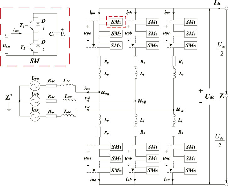
Figure 1 shows a lumped schematic of the MMC. Among this figure, Z and Z′ represent the neutral points (Uzz’ = 0). Rac, Lac, and R0, L0 indicate the equivalent resistance and inductance of AC grid and per bridge arm, respectively; upk, unk, and ipk, ink (k = a, b, c), respectively, represent the SM voltages and bridge arm current in the high-side and low-side bridge arms; the AC and DC grid voltages are expressed as Usk and Udc, respectively; uvk and ivk are AC voltage and current output by MMC.z
By using Kirchhoff’s laws, the mathematical model for AC circuit and DC circuit of MMC in Figure 1 can be derived separately as
where Udiffk = (Unk − Upk)/2 and Ucomk = (Unk + Upk)/2 denote the differential-mode voltage (DMV) and common-mode voltage (CMV) in phase k, respectively; ilk = (ipk + ink)/2 denotes the loop current of phase k, which consists of DC component and second harmonic components (Li et al., 2020); R = Rac + R0/2; L = Lac + L0/2.
Conducting Park Transformation on Eq. 1 for better control effect, Eq. 1 in dq reference frame can be transformed as
where ω is the fundamental grid angular frequency; Usd ,ivd, Udiffd, Ucomd, ilq and Usq, ivq, Udiffq, Ucomd, ilq are d-axis and q-axis component of corresponding electrical variables in Eq. 1, respectively.
Figure 2 shows the common hierarchical control structure of the MMC-HVDC control system, consisting of three control levels which ensure the proper operation of MMC from different dimensions. Among them, the station-level control provides the DMV and CMV in Eq. 1 by controlling the inner-loop current ivk precisely according to the reference value of DC voltage, active power and reactive power, which decides the control effects of MMC directly.
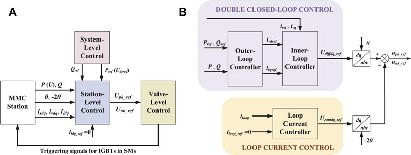
FIGURE 2. Block diagram of overall control architecture, (A) block diagram of three control levels of MMC, (B) detailed station-level control of MMC.
When the AC grid condition in Figure 1 become unbalanced, the grid voltage and current may contain the positive-sequence, negative-sequence and zero-sequence components, respectively. Since the transformer on the AC side often adopts the Y-Δ connection method in actual projects, the zero-sequence component of valve-side current is eliminated. Thus, the MMC controller is designed without considering the zero-sequence component in this paper. Due to the structure of the three-phase circuit on the AC side of MMC is approximately symmetrical in Figure 1, the mathematical model for AC circuit of MMC under unbalanced grid conditions can be rewritten from Eq. 2 as
where
According to Eq. 3, the inner-loop controller in Figure 2B can be further decomposed into two parts, namely, positive- and negative-sequence inner-loop controllers, which collaborate to achieve different control objectives by controlling the positive current
It should be noted that the reference value of loop current in the DC circuit of MMC is always set to zero during the whole control process in Figure 2, which means the loop current controller is independent of the unbalanced grid conditions. Therefore, this paper is focused on the improved double closed-loop control of MMC in Figure 2B which aims to obtain constant active and reactive power as well as distortionless grid current at any time especially when the grid condition is unbalanced.
3 Improved Sliding-Mode Vector Control for Modular Multi-Level Converter Using Extended Reactive Power
The traditional AC-side complex power S can be expressed as
where “*” denotes the conjugate of a complex vector; Uα, iα and Uβ, iβ are the α-axis and β-axis components of the voltage and current on the AC side, respectively.
Thus, the traditional power can be expressed as
When the traditional active and reactive power are chosen as the controlled variables of outer-loop controller in Figure 2 under unbalanced grid conditions, the active and reactive power will contain 2ω oscillations otherwise the grid current will have non-sine aberration, which is pernicious to the grid operation and the MMC itself. Consequently, the control method of MMC needs further improvement to be more applicable under unbalanced grid conditions.
In this paper, an ERP is introduced to improve the control performance of MMC under unbalanced grid conditions (Sun and Lipo, 2006), which can be expressed as
where,
When the grid condition becomes unbalanced, the grid voltage and current can be calculated as
where
According to the rotating direction of forward and backward dq reference frame, the delayed grid voltage vector under unbalanced grid condition can be expressed as
Substituting Eqs 7, 8 into Eqs 5, 6, the active power, TRP and ERP under unbalanced grid condition can be expressed as
where, P0, Q0, and
For better illustration, the coefficients of 2ω cosine and sinusoidal components of the active power, TRP, and ERP can be expressed in the matrix form as
According to Eq. 10, the outer-loop controller in Figure 2 which select active power and reactive power as controlled variables (P/Q control) to obtain constant output power can be designed.
For the PIVC using TRP, the positive and negative current reference value in their corresponding synchronous frame which are the reference inputs of the positive- and negative-sequence inner-loop controllers can be derived as
Since the reference values of active and reactive power (P0ref, Q0ref) are default setting received from system-level control in Figure 2, there are only two available controlled variables left (choose two controlled variables from P2c, Q2c, P2s, Q2s), which should eliminate the 2ω oscillations in active power and reactive power simultaneously.
It can be concluded from Eq. 10 that
Obviously, Eqs 12, 13 cannot hold at the same time which means the 2ω oscillations in TRP still exist when the 2ω oscillating component coefficients of active power in Eq. 11 are set to zero (P2cref = P2sref = 0) under unbalanced grid conditions. Consequently, they cannot be eliminated concurrently by adopting TRP under unbalanced grid conditions, otherwise, it will only lead to distortion of the AC current with high harmonics.
Similarly, for the ERP, it can be seen from Eq. 10 that
which means the 2ω oscillations in ERP will be eliminated completely with grid current keeping sinusoidal when choose P2c and P2s as controlled variables and set them to zero under unbalanced grid conditions, which is why the ERP is more suitable than TRP under unbalanced conditions as well as reducing the control complexity to improve the control performance.
Therefore, choosing active power and the ERP as controlled variables under unbalanced conditions with P2c = P2s = 0 in Eq. 10, the positive- and negative-sequence current reference value in their corresponding synchronous frame can be derived as
where
Moreover, when grid condition keeps balanced, it can be seen from Eqs 5, 6 that
It can be seen from Eq. 16 that the ERP can still remain effective under balanced grid condition which increases the applicability of the proposed control strategy.
After obtaining the reference values of positive- and negative-sequence dq form grid current in Eq. 15, the next-step work is to design a better inner-loop controller to track these reference value accurately. Thus, an ISMVC strategy is proposed in this paper to enhance the control performance of the inner-loop controller in response speed and robustness compared with the traditional PI control strategy. Since the control structure of the positive- and negative-sequence inner-loop controllers are identical, the rest of this section will focus on the positive-sequence inner-loop controller as an example.
The first stage in the design of SMC is to select an effective sliding surface. Due to the minimal steady-state error and great chattering rejection (Jiang and Gao, 2021), the integral sliding surface is adopted in this paper to improve the steady-state control performance, which can be designed as
where
To guarantee that the reaching and sliding conditions of SMC which enables uncertain chaotic systems to reach sliding-mode surface within finite time are satisfied, a Lyapunov function (Wang et al., 2019; Wang R. et al., 2020) is defined as
where, K is a positive constant.
The derivative of V can be calculated as
From Eqs 18, 19, the derivative of S can be calculated as
Taking Eq. 3 into Eq. 22, the derivative of S can be rewritten as
where
For the purpose of better dynamic performance and robustness with less chattering phenomena compared with the conventional exponential trending law (Mozayan et al., 2016), an improved exponential trending law is proposed as follows:
where, ɛ1, ɛ2, k1, k2 are positive control parameters; g and h are positive power parameters; sat (Si) denote the saturation function which can be expressed as
where, βi represents the range of the boundary layer; i = 1, 2.
In Eq. 24, the saturation function is adopted to design a boundary layer on both sides of the sliding surface which can reduce the high-frequency chattering phenomena introduced by traditional sign-function sgn (Si). −ɛi|e|hsat (Si) and −kiSi are variable and constant velocity term, respectively, which work together to propel the state trajectory towards the sliding surface with adaptive speed. Thus, good dynamic performance and less chattering phenomena can be balanced effectively.
Substituting Eq. 24 into Eq. 21, the derivative of function V can be rewritten as
Obviously, it can be seen from Eq. 20 to Eq. 26 that function V and its derivative are positive-definite and negative-definite, respectively, which means that the proposed ISMVC strategy is proved to be asymptotically stable according to the Lyapunov theory.
Combining Eqs 23, 24, the actual control variables of positive-sequence inner-loop controller
Similarly, the actual control variables of the negative-sequence inner-loop controller
where
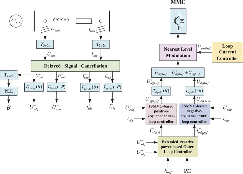
Figure 3 shows the control diagram of the proposed ISMVC for MMC. First, the ERP is adopted in the design of the outer-loop controller to obtain the reference value of the positive- and negative-sequence grid current in dq reference frame which are regarded as the input reference of the ISMVC-based positive- and negative-sequence inner-loop controllers. Then, the reference value of DMV can be deduced while the CMV reference can be easily obtained from loop current controller. Finally, the triggering signals for IGBT in SMs can be calculated by the nearest level modulation (NLM) method (Chen et al., 2020). In addition, it should be noted that the positive- and negative-sequence components of the grid voltage and current are extracted by delayed signal cancellation (DSC) strategy (Timbus et al., 2007).
4 Simulations
4.1 Simulation Model
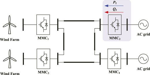
To validate the effectiveness of the proposed ISMVC strategy combined with ERP for MMC, a four-terminal MMC-based DC power system simulation shown in Figure 4 is carried out in PSCAD/EMTDC whose sampling frequency set as 50 kHz to consistent with practical projects. The DC-bus voltage stability and the power balance of the DC system are controlled by other MMCs, since we choose MMC2 as an example to adopt the proposed ISMVC strategy with ERP to achieve constant power control under different grid conditions. The simulation parameters are illustrated in Table 1.
Contrastive simulation experiments are carried out for the MMC2 with different control strategies and reactive power definitions under both balanced and imbalanced grid conditions, which are illustrated in Figures 5–8. To simplify the analysis, novel ISMVC and novel PIVC are used to designate the ISMVC and PIVC using the ERP, respectively, while traditional ISMVC denotes the ISMVC using TRP in this section.
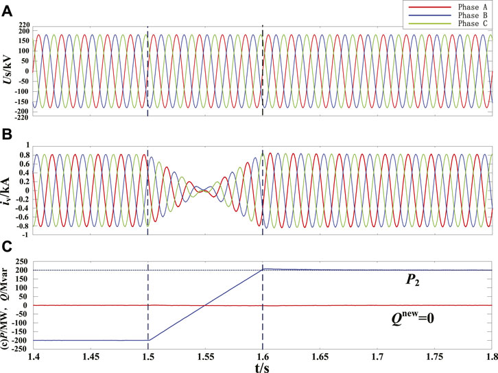
FIGURE 5. Simulation results under balanced grid condition, (A) AC grid voltage at MMC2 side, (B) AC grid current output by MMC2, (C) active power and ERP output by MMC2 using the novel ISMVC.
4.2 Case Study Under Balanced Grid Condition
The control performance of MMC2 under balanced grid condition is analyzed in this part to show the effectiveness of the proposed novel ISMVC strategy. The initial reference value of active and reactive power are set to be −200 MW and 0 MVar, respectively. Load flow reversal are setup during 1.5–1.6 s while the reference value of active power change linearly from −200 to 200 MW within 0.1 s. It can be seen from Figure 5 that the novel ISMVC can achieve accurate tracking of active and reactive power references, validating that the ERP can work effectively under balanced grid condition. At t = 1.5 s, as the load flow begins to reverse, the active power output by MMC2 can accurately track the real-time change of reference values with low overshoot, while the valve-side current always follows the trend of active power smoothly. Therefore, the novel ISMVC is feasible for MMC under balanced grid condition.
4.3 Case Studies Under Unbalanced Conditions
Figure 6 compares the control performances of the traditional ISMVC and novel ISMVC strategy when the control objective is to suppress the 2ω oscillations in active power output by MMC2 under unbalanced grid condition. The initial power reference is the same as Figure 5. At t = 1.5 s, as a 50% voltage dip in the phase A (a phase A high-impedance-grounded fault is set in the simulation), the three-phase grid voltages become unbalanced. Although the traditional ISMVC keeps the active power constant under unbalanced condition, the 2ω oscillations with an amplitude of 80 MW in reactive power still exists, which means that the traditional ISMVC cannot eliminate the 2ω oscillations in active power and reactive power simultaneously under imbalanced grid voltages. On the contrary, the active power and the ERP output by MMC2 can accurately track their constant reference values while obtaining sinusoidal valve-side grid current which means that the 2ω oscillations in the active power and ERP can be eliminated at the same time by using the novel ISMVC. According to the figure, it can be seen that the ERP is more appropriate to be a controlled variable in constant power control of MMC than the TRP.
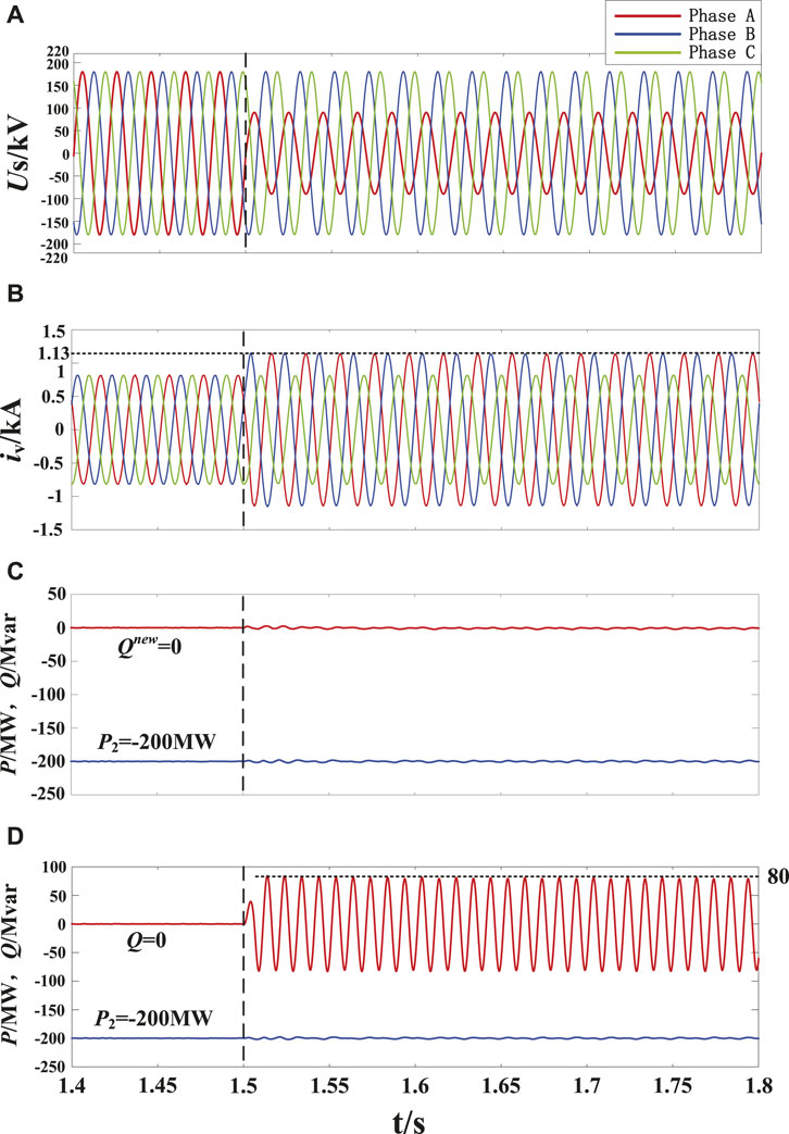
FIGURE 6. Control performance of the traditional ISMVC and novel ISMVC under unbalanced grid condition, (A) AC grid voltage at MMC2 side, (B) AC grid current output by MMC2, (C) active power and ERP output by MMC2 using the novel ISMVC, (D) active power and reactive power output by MMC2 using the traditional ISMVC.
Figure 7 shows the control performances of restraining negative-sequence current of MMC2 under unbalanced grid condition by using the novel ISMVC. The initial power reference and the voltage dip time of phase A are the same as Figure 6. It can be seen that the valve-side grid current remain three phase symmetry all the time and their amplitude only increases by 19.75% compared with that before the voltage dip, which means suppressing the negative-sequence current can effectively restrain the increase level of the fault current and facilitate the safe and economic operation of MMC under unbalanced grid condition. However, since the negative-sequence voltage has not been eliminated, there is still a certain amount of 2ω oscillations in active power and ERP output by MMC2. Besides, it should be noted that as the negative-sequence current has been eliminated completely, the amplitude of the 2ω oscillations in active power and ERP is only about 40MW, which is lower than that in Figure 6.
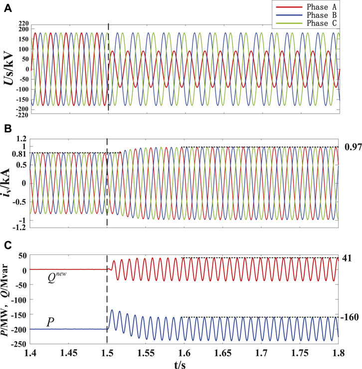
FIGURE 7. Control performances of restraining negative sequence current of MMC2 under unbalanced grid condition, (A) AC grid voltage at MMC2 side, (B) AC grid current output by MMC2, (C) active power and ERP output by MMC2 using the novel ISMVC.
Figure 8 contrasts the novel ISMVC with the novel PIVC in terms of the dynamic control responses and robustness under unbalanced grid condition, where the initial power reference and voltage dip time of phase A are the same as Figure 6. It can be seen from Figure 8 that the response speed of active power and ERP controlled by ISMVC strategy is better than that controlled by PIVC strategy which has smaller overshoot and faster response when the grid voltage dip occurs. At t = 1.7s, the bridge arm inductance changes from 36.7 to 45 mH which simulates the random parameter perturbations during the actual operation of MMC. It can be seen clearly that when the PIVC strategy applied to MMC2, the active power and ERP are significantly affected during parameter perturbations. On the contrary, the variation of parameters only has slight influence which can be negligible on the active power and ERP controlled by the proposed ISMVC strategy which can still accurately track their reference values. Moreover, the chattering phenomenon has been suppressed to a small range thanks to the improved SMC strategy. According to the simulation results, it can be seen that the proposed ISMVC has a greater advantage over the PIVC in terms of dynamic response and robustness, which proves that the ISMVC can fully exploit the superiority of the ERP under unbalanced grid condition.
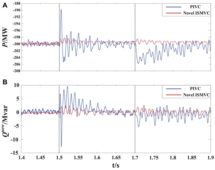
FIGURE 8. Simulation results of dynamic power responses and robustness using the PIVC and novel ISMVC, (A) active power output by MMC2 using the PIVC and novel ISMVC, (B) ERP output by MMC2 using the PIVC and novel ISMVC.
5 Conclusion
This paper proposes an ISMVC strategy combined with ERP for MMC under balanced and unbalanced grid conditions. The proposed method guarantees the valve-side grid current sinusoidal when eliminating the 2ω oscillations in active power and ERP simultaneously under unbalanced grid conditions. Faster dynamic response, better robustness and less chattering phenomena are provided by the improved SMC adopted in the positive- and negative-sequence inner-loop controllers of MMC due to the novel design of the sliding surface and reaching law, which can fully exerts the advantages of the ERP. Contrastive simulations of a four-terminal MMC-based DC power system based on the ISMVC and PIVC combined with the TRP and ERP are carried out to confirm the effectiveness and superiority of the proposed method under both balanced and unbalanced grid conditions. Therefore, the proposed method can work effectively under any grid conditions with fast dynamic response and good robustness.
Data Availability Statement
The original contributions presented in the study are included in the article/Supplementary Material, further inquiries can be directed to the corresponding author.
Author Contributions
TG: Conceptualization, writing-original draft. XZ: Editing. WZ:Editing. HL: Software. YL: Writing-review. QS: Data curation.
Conflict of Interest
Author TG was employed by Stare Grid Shenyang Electric Power Supply Company.
The remaining authors declare that the research was conducted in the absence of any commercial or financial relationships that could be construed as a potential conflict of interest.
Publisher’s Note
All claims expressed in this article are solely those of the authors and do not necessarily represent those of their affiliated organizations, or those of the publisher, the editors and the reviewers. Any product that may be evaluated in this article, or claim that may be made by its manufacturer, is not guaranteed or endorsed by the publisher.
References
Akagi, H., Kanazawa, Y., and Nabae, A. (2008). Instantaneous Reactive Power Compensators Comprising Switching Devices without Energy Storage Components. IEEE Trans. Industry Appl. IA-20, 625–630.
Chen, H., and Xu, Z. (2007). Transient Model and Controller Design for Vsc-Hvdc Based on Synchronous Reference Frame. Trans. China Electrotechnical Soc. 22, 121–126.
Chen, X., Liu, J., Song, S., and Ouyang, S. (2020). Circulating Harmonic Currents Suppression of Level-Increased Nlm Based Modular Multilevel Converter with Deadbeat Control. IEEE Trans. Power Electron. 35, 1. doi:10.1109/tpel.2020.2982781
Dan, S., Wang, X., Nian, H., and Zhu, Z. Q. (2018). A Sliding-Mode Direct Power Control Strategy for Dfig under Both Balanced and Unbalanced Grid Conditions Using Extended Active Power. IEEE Trans. Power Electron. 33, 1.
Freytes, J., Li, J., De-Preville, G., and Thouvenin, M. (2021). Grid-Forming Control with Current Limitation for Mmc under Unbalanced Fault Ride-Through. IEEE Trans. Power Deliv. 36, 1. doi:10.1109/tpwrd.2021.3053148
Guo, C., Yang, J., and Zhao, C. (2019). Investigation of Small-Signal Dynamics of Modular Multilevel Converter under Unbalanced Grid Conditions. IEEE Trans. Ind. Electron. 66. doi:10.1109/tie.2018.2831193
Hao, Q., Li, Z., Yue, C., Gao, F., and Wang, S. (2020). Small-Signal Model and Dynamics of Mmc- Hvdc Grid under Unbalanced Grid Conditions. IEEE Trans. Power Deliv. 36, 1.
Hemdani, A., Dagbagi, M., Naouar, W. M., Idkhajine, L., Slama Belkhodja, I., and Monmasson, E. (2015). Indirect Sliding Mode Power Control for Three Phase Grid Connected Power Converter. IET Power Electron. 8, 977–985. doi:10.1049/iet-pel.2013.0945
Hu, J., Shang, L., He, Y., and Zhu, Z. Q. (2010). Direct Active and Reactive Power Regulation of Grid-Connected Dc/ac Converters Using Sliding Mode Control Approach. IEEE Trans. Power Electron. 26, 210–222.
Jiang, B., and Gao, C. (2021). Decentralized Adaptive Sliding Mode Control of Large-Scale Semi-markovian Jump Interconnected Systems with Dead-Zone Input. IEEE Trans. Automatic Control. 67, 1.
Kong, M., Tang, G., Zhiyuan, H. E., and Yang, J. (2013). A Control Strategy for Modular Multilevel Converter Based Hvdc of Unbalanced Ac Systems. Proc. Csee 33, 41–49.
Li, B., Xie, Y., Wen, W., and Guan, T. (2020). Improved Sliding-Mode Control for Mmc in Dc Power System. IET Renew. Power Generation 14. doi:10.1049/iet-rpg.2020.0493
Liang, Y. (2017). “Direct Power Control Strategy Based on Reduced Order Vector Resonant Controller for Mmc-Hvdc under Unbalanced Grid Voltages,” in Proceedings of the CSEE.
Liu, Y., Huang, M., Chi, K. T., Iu, H. C., and Zha, X. (2021). Stability and Multiconstraint Operating Region of Grid-Connected Modular Multilevel Converter under Grid Phase Disturbance. IEEE Trans. Power Electron. 36, 1. doi:10.1109/tpel.2021.3078465
Long, B., Cao, T., Shen, D., Rodriguez, J., Guerrero, J. M., and Chong, K. T. (2021). Sequential Model Predictive Fault-Tolerance Control for T-Type Three-Level Grid-Connected Converters with LCL Filter. IEEE Trans. Ind. Electron. 69, 1. doi:10.1109/tie.2021.3114711
Mozayan, S. M., Saad, M., Vahedi, H., Fortin-Blanchette, H., and Soltani, M. (2016). Sliding Mode Control of Pmsg Wind Turbine Based on Enhanced Exponential Reaching Law. IEEE Trans. Ind. Electron. 63, 6148–6159. doi:10.1109/tie.2016.2570718
Nami, A., Liang, J., Dijkhuizen, F., and Demetriades, G. D. (2015). Modular Multilevel Converters for Hvdc Applications: Review on Converter Cells and Functionalities. IEEE Trans. Power Electron. 30, 18–36. doi:10.1109/tpel.2014.2327641
Nian, H., and Cheng, P. (2013). Resonant Based Direct Power Control Strategy for Pwm Rectifier under Unbalanced Grid Voltage Condition. Trans. China Electrotechnical Soc.
Song, J., Zheng, W. X., and Niu, Y. (2021). Self-Triggered Sliding Mode Control for Networked Pmsm Speed Regulation System: A Pso-Optimized Super-Twisting Algorithm. IEEE Trans. Ind. Electron. 69, 1.
Sun, Y., and Lipo, T. A. (2006). Modeling and Analysis of Instantaneous Active and Reactive Power for Pwm Ac/dc Converter under Generalized Unbalanced Network. IEEE Trans. Power Deliv. 21, 1530–1540.
Timbus, A. V., Rodriguez, P., Teodorescu, R., Liserre, M., and Blaabjerg, F. (2007). “Control Strategies for Distributed Power Generation Systems Operating on Faulty Grid,” in IEEE International Symposium on Industrial Electronics.
Wang, G., Sun, C., Liu, R., Wang, F., and Feng, L. I. (2015). Modular Multilevel Converter Control Strategy Based on Arm Current Control. Proc. Chin. Soc. Electr. Eng. 35, 458–464.
Wang, R., Sun, Q., Ma, D., and Hu, X. (2020). Line Impedance Cooperative Stability Region Identification Method for Grid-Tied Inverters under Weak Grids. IEEE Trans. Smart Grid 11, 2856–2866.
Wang, R., Sun, Q., Ma, D., and Liu, Z. (2019). The Small-Signal Stability Analysis of the Droop-Controlled Converter in Electromagnetic Timescale. IEEE Trans. Sustain. Energ. 10, 1. doi:10.1109/tste.2019.2894633
Wang, R., Sun, Q., Tu, P., Xiao, J., and Wang, P. (2021). Reduced-order Aggregate Model for Large-Scale Converters with Inhomogeneous Initial Conditions in Dc Microgrids. IEEE Trans. Energ. Convers. 36. doi:10.1109/tec.2021.3050434
Wang, S., Dragicevic, T., Gao, Y., Chaudhary, S. K., and Teodorescu, R. (2020). Machine Learning Based Operating Region Extension of Modular Multilevel Converters under Unbalanced Grid Faults. IEEE Trans. Ind. Electron. 68, 1.
Wei, X., Sun, H., Wei, X., Qian, M. A., and Fengge, X. U. (2011). Control Strategy about Power Quality Improvement for Vsc-Hvdc under Unbalanced Ac Grid Conditions. Proc. Csee 31, 8–14.
Xia, X., Xu, L., Zhao, X., Zeng, X., and Yi, H. (2021). Modular Multilevel Converter Predictive Control Strategy Based on Energy Balance. J. Power Electron. 21. doi:10.1007/s43236-021-00225-9
Yang, H., and Nian, H. (2015). “Stability Analysis of Grid-Connected Converter Based on Interconnected System Impedance Modeling under Unbalanced Grid Conditions,” in International Conference on Electrical Machines & Systems.
Zhang, Y., and Qu, C. (2015). Model Predictive Direct Power Control of Pwm Rectifiers under Unbalanced Network Conditions. IEEE Trans. Ind. Electron. 62, 1. doi:10.1109/tie.2014.2387796
Zhou, Y., Jiang, D., Guo, J., Hu, P., and Liang, Y. (2013). Analysis and Control of Modular Multilevel Converters under Unbalanced Conditions. IEEE Trans. Power Deliv. 28, 1986–1995. doi:10.1109/tpwrd.2013.2268981
Keywords: modular multi-level converter (MMC), extended reactive power (ERP), sliding-mode control (SMC), vector control (VC), unbalanced grid condition
Citation: Guan T, Zhao X, Zheng W, Liu H, Liu Y and Sun Q (2022) Improved Sliding-Mode Vector Control Strategy Combined With Extended Reactive Power for MMC Under Unbalanced Grid Condition. Front. Energy Res. 10:874533. doi: 10.3389/fenrg.2022.874533
Received: 12 February 2022; Accepted: 01 March 2022;
Published: 24 March 2022.
Edited by:
Wei Hu, Zhejiang University, ChinaReviewed by:
Xiangke Li, Hong Kong Polytechnic University, Hong Kong SAR, ChinaTianyang Zhao, Jinan University, China
Copyright © 2022 Guan, Zhao, Zheng, Liu, Liu and Sun. This is an open-access article distributed under the terms of the Creative Commons Attribution License (CC BY). The use, distribution or reproduction in other forums is permitted, provided the original author(s) and the copyright owner(s) are credited and that the original publication in this journal is cited, in accordance with accepted academic practice. No use, distribution or reproduction is permitted which does not comply with these terms.
*Correspondence: Tianyi Guan, OTMxMTYzNzQ1QHFxLmNvbQ==
 Tianyi Guan
 Xin Zhao1
 Yao Liu
 Qiuye Sun