 Fan Feng
 Jingyang Fang
 Ujjal Manandhar3
- 1School of Marine Engineering and Technology, Sun Yat-sen University, Zhuhai, China
- 2School of Control Science and Engineering, Shandong University, Jinan, China
- 3School of Electric and Electronic Engineering, Nanyang Technological University, Singapore, Singapore
The impedance-based criterion has turned out to be a very effective tool for the stability analysis of the dual active bridge (DAB) converter with its input LC filter. While the input impedance of the DAB converter is highly dependent on the modulation methods, the influences of the modulation methods on the input impedances of the DAB converters are still not clear. To close this gap, three typical modulation methods of DAB converters, traditional single-phase-shift (SPS), dual-phase-shift (DPS) and the emerging cooperative triple-phase-shift (CTPS) modulation, are studied in this paper. First, the full-order input impedance models of the DAB converter with these modulation methods are derived for the first time. Second, based on the developed models, the impacts of these modulation schemes on the DAB input impedances are revealed. An interesting phenomenon is found that the open-loop impedances of SPS-DAB and DPS-DAB converters present the characteristics of the parallel-connected inductor and capacitor, while the open-loop impedance of CTPS-DAB converter presents the resistor characteristics. Third, the optimal modulation scheme for system stability is investigated. Finally, the theoretical analysis has been validated by the experimental results.
Introduction
The dual active bridge (DAB) converter is drawing more and more attention in both academics and industry because of its advantages of galvanic isolation, high power density and efficiency (Zhao et al., 2014; Alonso et al., 2010; Hengsi Qin and Kimball, 2012). The state-of-the-art researches focus on the modulation methods (Kheraluwala and De Doncker, 1993; Inoue and Akagi, 2007; Hua Bai and Mi, 2008; Zhao et al., 2012; Wu et al., 2018), soft-switching solution (Oggier et al., 2010; Huang et al., 2016), control strategy (Song et al., 2018; Takagi and Fujita, 2018; Shan et al., 2018; Oggier et al., 2014) and optimization of hardware design (Fan and Li, 2011; Wang et al., 2009). The typical configuration of a DAB converter-based DC microgrid is shown in Figure 1. The switching converters are necessary for the power transfer between the source and dc/ac loads. However, they also introduce strong electromagnetic interference (EMI) due to the high-frequency switching. These high-frequency components can cause improper operation of other EMI sensitive loads/equipment in this microgrid. Compliance with electromagnetic interference (EMI) standards, the insertion of an LC filter between the DAB converter and the DC bus is required (Weichel et al., 2010; Weise, 2013). However, although the DAB converter is designed properly for stand-alone operation (Shi et al., 2017), the stability can be a problem when the DAB converter is cascaded with its LC filter. This instability issue is actually caused by the coupling of the DAB converter and the LC filter.
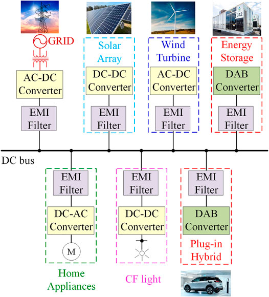
FIGURE 1. System configuration of a DAB converter enabled dc microgrid.
Similar instability issues have also been found in other cascaded systems (Middlebrook and Cuk, 1976; Kelkar and Lee, 1983). Existing approaches (Sun, 2011; Zhang et al., 2015) to analyzing the stability necessitate the input impedance of the DAB converter Zin_DAB and the output impedance of the LC filter Zout_LC, as shown in Figure 1. If the minor loop gain Tm, which is organized as the ratio of Zout_LC to Zin_DAB, does not satisfy the Nyquist criterion, the resonant frequency of the input LC filter will create unstable problems.
The determination of the required DAB input impedance model is highly dependent on the modulation methods of the DAB converters. Up to now, the most widely used method is the single-phase-shift (SPS) modulation (Kheraluwala and De Doncker, 1993; Inoue and Akagi, 2007). Through adjusting the outer phase-shift between the output voltages of the two H-bridges, the transferred power can be easily regulated. However, the large circulating current is generated in the SPS-DAB converter, which can lower the efficiency of the whole system (Harrye et al., 2014; Wen et al., 2014; Karthikeyan and Gupta, 2016). To reduce the circulating current, the concept of the dual-phase-shift (DPS) modulation is first proposed in (Hua Bai and Mi, 2008). Compared to SPS, an additional inner phase-shift ratio is applied to the H-bridges, reducing the circulating current and current stress. Furthermore, in Literature Wu, et al. (Wu et al., 2018), the cooperative triple-phase-shift (CTPS) modulation is proposed to eliminate the dual side circulating currents. With the CTPS method, better current characteristics, including the current stress, average absolute, and RMS values of the inductor current, can be achieved. Therefore, the CTPS method has gained increasing attention in many applications: Solid State Transformers (Shi et al., 2019), energy storage systems (Feng et al., 2020), and the DAB variants (Fang et al., 2020; Cao et al., 2021). Apart from affecting the circulating current, different modulation methods also lead to different performances of the DAB converter. The differences of the steady-state operation and dynamic responses of DAB converters with SPS and DPS modulation methods have been compared in (Hua Bai et al., 2010; Hou and Li, 2019). However, to the best of the authors’ knowledge, the influences of these modulation methods on the DAB input impedance characteristics and stability performance have been rarely studied. In the existing literature (Tian et al., 2016; Ye et al., 2016; Mueller and Kimball, 2017), the stability of the DAB based cascaded configuration is analyzed only considering SPS modulation. The differences of the input impedances of the DAB converters with SPS, DPS and CTPS modulation are not clear. Since the stability criterion directly depends on the input impedance, the stability performance of the DAB converter with its LC filter could be different due to the different modulation methods applied.
The purpose of this paper is to present the comparative study on the influences of different modulation schemes on the stability of the DAB-based cascaded topologies. Three typical modulation schemes, SPS, DPS and CTPS, are selected and the input impedances of the DAB converter with these three modulation schemes are derived and analyzed. This paper presents the following contributions:
• The full-order input impedance models of the DAB converter with three typical modulation methods: SPS, DPS and CTPS are developed for the first time.
• The effects of SPS, DPS and CTPS modulation methods on the input impedance characteristics of the DAB converters are disclosed.
• The stability performance of SPS-, DPS- and CTPS-DAB converter with the LC filter are analyzed and compared. The optimal modulation method from stability point of view has been pointed out, which is further verified by experimental results.
The rest of this paper is organized as follows. The operation mechanisms of the SPS, DPS and CTPS modulation methods are analyzed in Operation Principles and Stability Analysis of DAB Converters With Input LC Filter. The input impedance models of the SPS-, DPS-, and CTPS-DAB converters are derived in Input Impedance Modeling of DAB Converters with SPS, DPS and CTPS Modulations. The SPS, DPS and CTPS modulation methods are compared in terms of stability performance of DAB converters with the LC filter in Stability Comparison of Cascaded System with SPS, DPS and CTPS Modulations. Experimental Results presents the experimental results to verify the theoretical analysis. The conclusion is given in Conclusion.
Operation Principles and Stability Analysis of DAB Converters With Input LC Filter
Operation principles of DAB converter with SPS, DPS and CTPS modulation methods.
Figure 2 shows the circuit topology of the DAB converter, which consists of two H-bridge and one high-frequency transformer. iL is the leakage inductor current. vh1 and vh2 are the output voltages of the input and output H-bridges, which can be calculated as:
where s1 and s2 are the switching functions at the input and output H-bridges, respectively; vdc is the voltage across the capacitance Cf; and vo is the output voltage of the DAB converter.
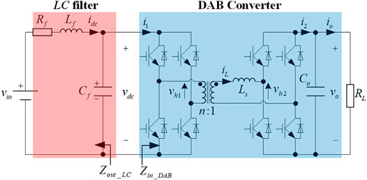
FIGURE 2. Circuit topology of the DAB converter with its input LC filter.
The operation principles of the DAB converter with different modulation methods are shown in Figure 3.
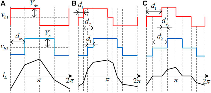
FIGURE 3. Operation principles of DAB converters with (A)SPS; (B) DPS; (C) CTPS.
Figure 3A depicts the operation mechanism of the SPS modulation method. In this method, two H-bridges both generate square voltage waveforms at the primary and secondary sides of the transformer. Through adjusting the outer phase shift ratio dφ between these two output voltages of the H-bridges, the direction and magnitude of the transferred power can easily be regulated. The switching functions s1_SPS and s2_SPS can be expressed as in (2).
For DPS modulation (Figure 3B), besides the phase shift dφ used in SPS, an additional duty ratio d1 is applied to the two H-bridges. The output voltages of the H-bridges are modulated as three-level waveforms. During the time intervals of the zero voltage of the three-level wave, the circulating power is zero. Therefore, compared to SPS method, DPS method reduces the current stress of the switches and increases the overall efficiency for the given transmission power. According to Figure 3B, the switching functions s1_DPS and s2_DPS in DPS are changed to (3).
In order to address the circulating current problem, three control variables, describing the duty ratio of vh1 (d1), vh2 (d2) and the phase shift between them (dφ) are used in CTPS modulation (Figure 3C). It has been shown in Literature Wu et al. (2018), in order to eliminate the circulating current, these three control variables should satisfy the constraint in (4).
where k = nVdc/Vo; and n is the turns ratio of the transformer.
The switching functions of CTPS can be derived from Figure 3C.
Stability Analysis of DAB Converters With Its LC Filter
For the cascaded system consisting of the DAB converter and the input LC filter, according to (Huang et al., 2016), the stability of the cascaded system depends on the minor loop gain Tm, which is expressed as follows:
where Zout_LC is the output impedance of the LC filter and Zin_DAB is the input impedance of the DAB converter. If and only if Tm satisfies Nyquist criterion, the stability of the cascaded system will be stable.
While the output impedance of the LC filter is given in (7), the input impedance model of the DAB converter should be determined for the stability analysis.
where Lf and Cf are the inductor and capacitor of the input filter, respectively; Rf is the leakage resistance of Lf.
Input Impedance Modeling of DAB Converters With SPS, DPS and CTPS Modulations
Generalized Averaging of DAB Converters
For the modeling of DAB converters, all the switches are considered as the ideal switches. So the voltage drop across the transistor diode and switching transients are negligible. Since the input filter capacitor is relatively large, the dynamics of the input filter capacitor are much slower than those of the DAB converter and therefore are neglected. iL and vo are taken as the state variables. The state equations are derived as:
where dot notation is used to indicate derivatives with respect to time; Ls is the leakage inductor of DAB converters; Co is the output filter capacitor; and RL is the equivalent load resistor.
Due to the ac characteristics of the DAB inductor current, the generalized state space averaging (GSSA) is applied. The idea of GSSA is based on the representation of the signal x(τ) on the interval
where
For the DAB converter, to represent the dc and ac components of the state variables and the switching functions, they are extended to index-0 and index-1 terms of their Fourier series, which can be derived from (9). Note that the index-1 coefficients of these variables have both real and imaginary parts. This leads to the following state variable vector,
where the subscripts denote the number of the Fourier series terms; the superscripts “R” and “I” mean the real and imaginary parts of the first terms, respectively. These rules apply in the entire paper.
Since iL is purely ac, and iL varies faster than vdc and vo, it is assumed that,
State variables are now reduced to the following vector,
Applying the Fourier series properties to 8) and 9) yields the GSSA state equations of the DAB converter:
where ωs = 2πfs. fs is the switching frequency.
The output vector
Input impedance modeling of DAB with SPS, DPS and CTPS modulations.
The small-signal model of the SPS-, DPS- and CTPS-DAB converters can be obtained by applying perturbation to the input variables vdc and d in the average model 15) and (16). The control signal d refers to dφ for SPS, and d1 for DPS and CTPS. Note that in this paper, for the variable x, its small-signal notation is
The open-loop small-signal model of the DAB converter is expressed in .
where A, B, C, D are system matrices, which are given as:
Note that the above model is valid for any modulation method of the DAB converter. The specific formulation of the small-signal model of the SPS-, DPS- and CTPS-DAB converters can be derived by substituting the corresponding switching functions.
Due to the symmetry of the operation waveforms shown in Figure 2, the index-0 coefficients of these switching functions are all equal to 0. Substituting (2), 3) and 5) into (11), the complex index-1 coefficients of the switching functions for SPS, DPS and CTPS modulation can be obtained. The real and imaginary parts of these coefficients are caLCulated in (19) (20) and (21).
Substituting 19)–21) into 18) produce the small-signal models for the DAB converter with SPS, DPS and CTPS modulation methods, respectively.
The transfer functions defined in Table 1 are obtained in (22) by solving the small-signal models of DAB converters using MATLAB. The analytical solutions of the open-loop transfer functions
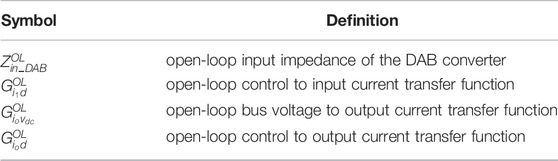
TABLE 1. Definitions for the transfer functions of the DAB.
The determination of the closed-loop impedances depends on the feedback control loops. Figure 4 shows the feedback control block diagram of the DAB converter. It should be mentioned that the same feedback control loop is applied to SPS-, DPS- and CTPS-DAB converters. Gc denotes the DAB controller and Gc = kp + ki/s. kp and ki are the proportional and integrational coefficients, respectively.
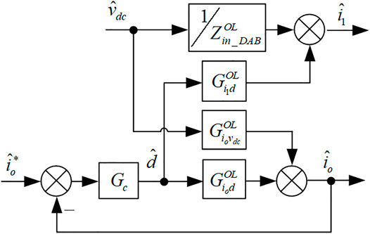
FIGURE 4. Control block diagram of DAB converters.
Substituting all the open-loop transfer functions into Figure 4, the closed-loop input impedances of DAB converters with SPS, DPS and CTPS are caLCulated using MATLAB, respectively. The unified expression of Zin_DAB is given as in:
where T is the loop gain of DAB converters and.
Stability Comparison of Cascaded System With SPS, DPS and CTPS Modulations
Input Impedance and Stability Comparison of Cascaded System With Different Modulations
To compare the influences of the modulation methods on the stability of the cascaded system, the input impedance of the DAB converter should be compared with the output impedance of the LC filter. The circuit parameters are shown in Table 2. The equilibrium point can be derived by solving 15) making

TABLE 2. Specifications of the DAB converter with LC filter.
The PI parameters for the DAB converters are selected to guarantee the same cut-off frequency for SPS, DPS and CTPS. According to Literature Erickson and Maksimovic (Erickson and Maksimovic, 2007), if the cut-off frequency of the closed-loop DAB converter is close to or greater than the resonant frequency of the input LC filter, the cascaded system tends to be unstable. Therefore, the cut-off frequencies of the closed-loop DAB converter with SPS, DPS and CTPS are all selected as 200 Hz, which is smaller than the LC filter resonant frequency 1,340 Hz.
For the stand-alone operation of the DAB converter, the poles of the closed-loop current control transfer function are shown in Figure 5. The eigenvalues of the current control transfer functions all appear in the left half-plane, indicating that the DAB converter under SPS/DPS/CTPS are all stable for standalone operation with the selected PI parameters.
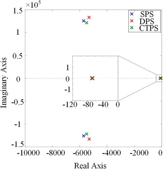
FIGURE 5. Poles of the closed-loop current control transfer function.
To assess the stability of the cascaded system, the Bode plots of the open-loop input impedances, the closed-loop input impedances of DAB converters and the output impedance of the LC filter are shown in Figure 6. The circuit and controller parameters are also shown in Table 2.
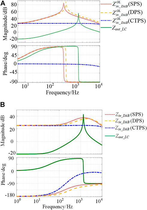
FIGURE 6. (A) Bode plots of open-loop input impedances of DAB converters. (B) Bode plots of closed-loop input impedances of DAB converters.
By Figure 6A, the characteristics of the open-loop DAB input impedances are highly affected by the modulation schemes.
As seen from Figure 6B, the comparisons between the closed-loop impedances and stabilities of SPS-, DPS-, and CTPS-DAB converters are summarized as:
• At low frequencies, the input impedances of DAB converters with SPS, DPS, and CTPS modulation methods show negative resistor characteristics.
• At high frequencies (beyond 600 Hz), Zin_DAB (SPS) and Zin_DAB (DPS) show a capacitive behavior, while Zin_DAB (CTPS) presents a positive resistance behavior.
• The closed-loop impedance of DAB converters intersects with Zout_LC around 1,030 Hz, which is the same with the open-loop impedance intersection freqeuencyAccording to the Middlebrook criterion, the same impedance intersection condition indicates that the system stability performance of open-loop and closed-loop operation should also be the same.
• At this intersection frequency, the negative impedance of Zin_DAB (SPS)/Zin_DAB (DPS) will lead to instability as the phase difference is larger than 180°. The resistive characteristics of Zin_DAB (CTPS) ensure that the CTPS-DAB converter has high stability robustness at the intersection frequency.
• Hence, for stability consideration, the CTPS modulation is preferred for the cascaded system.
Case. Studies for the Stability ComparisonTo verify the influence of the modulation methods on the stability, the Nyquist plots of the minor loop gain Tm, are drawn using MATLAB. The circuit parameters are shown in Table 2.The Nyquist plots of Tm, which is the ratio of Zin_DAB to Zout_LC, are shown in Figure 7. When SPS or DPS is applied, the cascaded system is not stable as the trajectory of Tm encircles the critical point (-1, 0). However, the trajectory of Tm no longer encircles (-1, 0) anymore when CTPS is applied. Therefore, CTPS is the optimal modulation methods for the cascaded system for stability consideration.

FIGURE 7. Nyquist plots of closed-loop minor loop gain Tm.
Experimental Results
To verify the theoretical analysis, the stability of the cascaded system with the SPS, DPS and CTPS modulation methods are tested through based on the OPAL-RT based hardware-in-the-loop (HIL) experimental system.
Figure 8 illustrates the overall structure of the HIL system. The real-time simulator OP5600 functions as the main circuit. To ensure the real-time behavior of the power switches, the sampling frequency is set as 2 MHz, 100 times faster than the switching frequency. The hardware controller is realized by dSPACE 1,202 (Microlab Box) with a sampling rate of 20 kHz. The analog signals of Ib, Vc and Vdc are generated by OP5600 and sent to the dSPACE controller. After calculation, the duty cycle information for the DAB converters will be sent from the dSPACE controller back to OP5600. The oscilloscope YOKOGAWA DL850E captured all the waveforms of the HIL system.
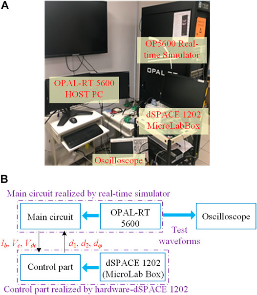
FIGURE 8. The HIL test system: (A) the picture of the HIL system; (B) the schematic diagram of the HIL system.
The steady-state waveforms of the single DAB converter with SPS, DPS and CTPS modulation methods are shown in Figure 9. The waveforms are all stable, which indicates that the DAB converters with SPS/DPS/CTPS are well designed for stand-alone operation. Additionally, Figure 10 further illustrates the effectiveness of the CTPS method on eliminating the dual side flow back currents. As seen, vh1 and vh2 always change their polarities when iL is equal to zero. Both dc side currents i1 and i2 (indicated in Figure 2) are always not less than zero.
FIGURE 9. Experimental waveforms of the single DAB converter with (A) SPS; (B) DPS; (C) CTPS.
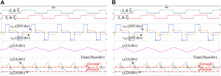
FIGURE 10. DC side current waveforms of the CTPS modulated DAB converters (A) light load; (B) heavy load.
Figures 11–13 show the dynamic performances of the DAB converter with SPS, DPS and CTPS, respectively. When the load steps between half load and full load conditions, it can be found that the dynamic performances of the DAB converter with SPS, DPS and CTPS are all good. The waveforms become stable after a short transient period, which is less than 3 ms. Similarly, when the input voltage steps between the 80% and 120% rated voltage (100 V) at full load condition, the dynamic waveforms of the DAB converter with SPS, DPS and CTPS are also good.
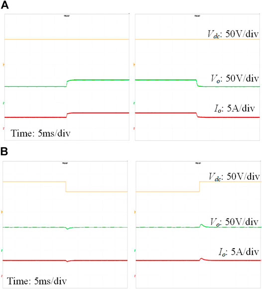
FIGURE 11. Dynamic waveforms of the single DAB converter with SPS: (A) when the load steps between half load and full load; (B) when the input voltage steps between 80% and 120% rated voltage.
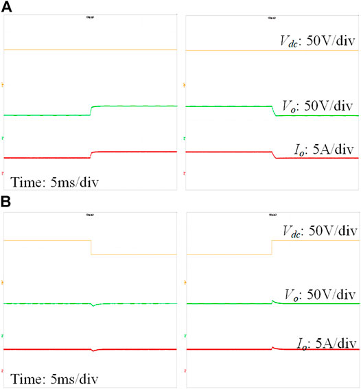
FIGURE 12. Dynamic waveforms of the single DAB converter with DPS: (A) when the load steps between half load and full load; (B) when the input voltage steps between 80% and 120% rated voltage.
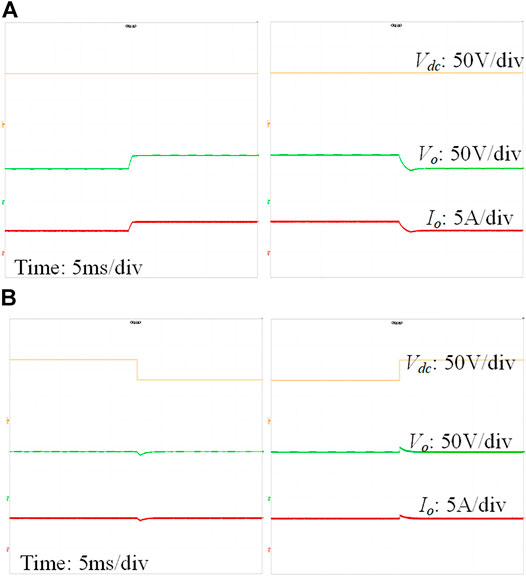
FIGURE 13. Dynamic waveforms of the single DAB converter with CTPS: (A) when the load steps between half load and full load; (B) when the input voltage steps between 80% and 120% rated voltage.
In summary, the experimental results given in Figures 9–13 show that the single DAB converter can operate properly with SPS, DPS and CTPS modulation methods.
Figure 14 shows the closed-loop operation waveforms of the DAB converter with SPS, DPS and CTPS modulations. The oscillation can be found when SPS or DPS modulation methods are applied, as shown in Figures 14A,B. This is because the input impedance of SPS- or DPS-DAB converter intersect with the output impedance of the input LC filter at 1,030 Hz, as shown in Figure 6. And the input impedance of SPS- or DPS-DAB converter shows capacitive impedance characteristics at this intersection frequency range. So, the resonance path is formed between the DAB converter with input LC filter. From Figures 14A,B, the oscillating frequency of the waveforms is around 1,030 Hz, which coincides the analysis of the Bode plots.
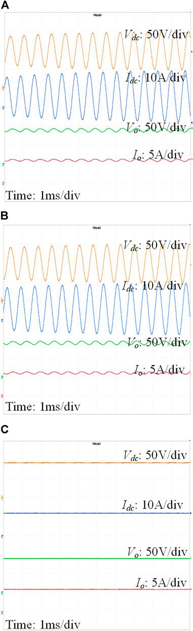
FIGURE 14. Waveforms of DAB converters in closed-loop operation (A) SPS; (B) DPS; (C) CTPS.
The dynamic performance of the CTPS-DAB converter with its LC filter is also tested and the results are shown in Figure 15. As shown, the dynamic waveforms of the CTPS-DAB converter with its LC filter are also stable under the load step change and the input voltage step change. Therefore, the experimental results prove that the CTPS modulation method presents better stability performance for the cascaded system compared to those of the SPS and DPS methods.
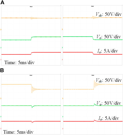
FIGURE 15. Dynamic waveforms of the CTPS-DAB converter with its LC filter: (A) when the load steps between half load and full load; (B) when the input voltage steps between 80% and 120% rated voltage.
Conclusion
The stability of the DAB-based cascaded systems with SPS, DPS and CTPS modulation methods have been assessed and compared in this paper. The open-loop and close-loop input impedances of DAB converters have been derived with respect to these modulation methods. The influences of different modulation schemes on the input impedance characteristics have been revealed. The resonant path which has been found between the SPS- or DPS-DAB converter and its LC filter can degrade the stability. Furthermore, the presented analysis has shown that the resistive input impedance of the CTPS-DAB converter ensures higher stability robustness. Experimental results verify the CTPS modulation is the optimal method for DAB-based cascaded systems as it provides the best stability performance compared to those of SPS and DPS modulation methods.
Data Availability Statement
The original contributions presented in the study are included in the article/Supplementary Material, further inquiries can be directed to the corresponding authors.
Author Contributions
FF contributed to the conception of the study and wrote the manuscript; JF performed the data analyses; HG contributed to analysis and manuscript preparation. UM and PX performed the experiment.
Funding
This research was funded by the Special project for marine economy development of Guangdong Province (GDNRC[2022]31).
Conflict of Interest
The authors declare that the research was conducted in the absence of any commercial or financial relationships that could be construed as a potential conflict of interest.
The reviewer YZ declared a shared affiliation with the author(s) HG, UM to the handling editor at the time of review.
Publisher’s Note
All claims expressed in this article are solely those of the authors and do not necessarily represent those of their affiliated organizations, or those of the publisher, the editors, and the reviewers. Any product that may be evaluated in this article, or claim that may be made by its manufacturer, is not guaranteed or endorsed by the publisher.
Appendix A1
The analytical solutions of
References
Alonso, A. R., Sebastian, J., Lamar, D. G., Hernando, M. M., and Vazquez, A. (2010). “An Overall Study of a Dual Active Bridge for Bidirectional DC/DC Conversion,” in Proceeding of the Energy Conversion Congress and Exposition (ECCE), Atlanta, GA, USA, 12-16 Sept. 2010 (IEEE), 1129–1135. doi:10.1109/ecce.2010.5617847
Cao, Y., Ngo, M., Burgos, R., Ismail, A., and Dong, D. (2021). Switching Transition Analysis and Optimization for Bidirectional CLLC Resonant DC Transformer. IEEE Trans. Power Electronics 37 (4), 3786–3800. doi:10.1109/TPEL.2021.3125265
Erickson, R. W., and Maksimovic, D. (2007). Fundamentals of Power Electronics. Norwell, MA: Springer Science & Business Media.
Fan, H., and Li, H. (2011). High-Frequency Transformer Isolated Bidirectional DC-DC Converter Modules with High Efficiency over Wide Load Range for 20 kVA Solid-State Transformer. IEEE Trans. Power Electron. 26 (12), 3599–3608. doi:10.1109/tpel.2011.2160652
Fang, F., Tian, H., and Li, Y. (2020). Coordination Control of Modulation index and Phase Shift Angle for Current Stress Reduction in Isolated AC–DC Matrix Converter. IEEE Trans. Power Electronics 36 (4), 4585–4596. doi:10.1109/TPEL.2020.3023719
Feng, F., Zhang, X., Zhang, J., and Gooi, H. B. (2020). Stability Enhancement via Controller Optimization and Impedance Shaping for Dual Active Bridge-Based Energy Storage Systems. IEEE Trans. Ind. Electronics 68 (7), 5863–5874. doi:10.1109/TIE.2020.2992947
Harrye, Y. A., Ahmed, K. H., and Aboushady, A. A. (2014). “Reactive Power Minimization of Dual Active Bridge DC/DC Converter with Triple Phase Shift Control Using Neural Network,” in Proceeding of the 2014 International Conference on Renewable Energy Research and Application (ICRERA), Milwaukee, WI, USA, 19-22 Oct. 2014 (IEEE), 566–571. doi:10.1109/icrera.2014.7016448
Hengsi Qin, H., and Kimball, J. W. (2012). Generalized Average Modeling of Dual Active Bridge DC-DC Converter. IEEE Trans. Power Electron. 27 (4), 2078–2084. doi:10.1109/tpel.2011.2165734
Hou, N., and Li, Y. W. (2019). Overview and Comparison of Modulation and Control Strategies for a Nonresonant Single-phase Dual-Active-Bridge DC–DC Converter. IEEE Trans. Power Electronics 35 (3), 3148–3172. doi:10.1109/TPEL.2019.2927930
Hua Bai, H., and Mi, C. (2008). Eliminate Reactive Power and Increase System Efficiency of Isolated Bidirectional Dual-Active-Bridge DC-DC Converters Using Novel Dual-Phase-Shift Control. IEEE Trans. Power Electron. 23 (6), 2905–2914. doi:10.1109/tpel.2008.2005103
Hua Bai, H., Ziling Nie, Z., and Mi, C. C. (2010). Experimental Comparison of Traditional Phase-Shift, Dual-Phase-Shift, and Model-Based Control of Isolated Bidirectional DC-DC Converters. IEEE Trans. Power Electron. 25 (6), 1444–1449. doi:10.1109/tpel.2009.2039648
Huang, J., Wang, Y., Li, Z., and Lei, W. (2016). Unified Triple-Phase-Shift Control to Minimize Current Stress and Achieve Full Soft-Switching of Isolated Bidirectional DC-DC Converter. IEEE Trans. Ind. Electron. 63 (7), 4169–4179. doi:10.1109/tie.2016.2543182
Inoue, S., and Akagi, H. (2007). A Bidirectional DC-DC Converter for an Energy Storage System with Galvanic Isolation. IEEE Trans. Power Electron. 22 (6), 2299–2306. doi:10.1109/tpel.2007.909248
Karthikeyan, V., and Gupta, R. (2016). Zero Circulating Current Modulation for Isolated Bidirectional Dual‐active‐bridge DC-DC Converter. IET Power Electronics 9 (7), 1553–1561. doi:10.1049/iet-pel.2015.0475
Kelkar, S., and Lee, F. (1983). Stability Analysis of a Buck Regulator Employing Input Filter Compensation. IEEE Power Electronics Specialists Conf. AES-20, 67–77. doi:10.1109/pesc.1983.7069838
Kheraluwala, M., and De Doncker, R. (1993). “Single Phase unity Power Factor Control for Dual Active Bridge Converter,” in Proceeding of the Conference Record of the 1993 IEEE Industry Applications Conference Twenty-Eighth IAS Annual Meeting, Toronto, ON, Canada, 2-8 Oct. 1993 (IEEE), 909–916. doi:10.1109/IAS.1993.299007
Middlebrook, R., and Cuk, S. (1976). “A General Unified Approach to Modelling Switching-Converter Power Stages,” in Proceeding of the 1976 IEEE Power Electronics Specialists Conference, Cleveland, OH, USA, 8-10 June 1976 (IEEE), 18–34. doi:10.1109/pesc.1976.7072895
Mueller, J. A., and Kimball, J. W. (2017). “Model-based Determination of Closed-Loop Input Impedance for Dual Active Bridge Converters,” in Proceeding of the 2017 IEEEApplied Power Electronics Conference and Exposition (APEC), Tampa, FL, USA, 26-30 March 2017 (IEEE), 1039–1046. doi:10.1109/apec.2017.7930824
Oggier, G., Garcia, G. O., and Oliva, A. R. (2010). Modulation Strategy to Operate the Dual Active Bridge DC-DC Converter under Soft Switching in the Whole Operating Range. IEEE Trans. Power Electronics 26 (4), 1228–1236. doi:10.1109/TPEL.2010.2072966
Oggier, G. G., Ordonez, M., Galvez, J. M., and Luchino, F. (2014). Fast Transient Boundary Control and Steady-State Operation of the Dual Active Bridge Converter Using the Natural Switching Surface. IEEE Trans. Power Electron. 29 (2), 946–957. doi:10.1109/tpel.2013.2256150
Shan, Z., Jatskevich, J., Iu, H. H.-C., and Fernando, T. (2018). Simplified Load-Feedforward Control Design for Dual-Active-Bridge Converters with Current-Mode Modulation. IEEE J. Emerg. Sel. Top. Power Electron. 6 (4), 2073–2085. doi:10.1109/jestpe.2018.2797998
Shi, H., Wen, H., Hu, Y., Yang, Y., and Wang, Y. (2019). Efficiency Optimization of DC Solid-State Transformer for Photovoltaic Power Systems. IEEE Trans. Ind. Electronics 67 (5), 3583–3595. doi:10.1109/TIE.2019.2914620
Shi, L., Lei, W., Li, Z., Huang, J., Cui, Y., and Wang, Y. (2017). Bilinear Discrete-Time Modeling and Stability Analysis of the Digitally Controlled Dual Active Bridge Converter. IEEE Trans. Power Electron. 32 (11), 8787–8799. doi:10.1109/tpel.2016.2640659
Song, W., Hou, N., and Wu, M. (2018). Virtual Direct Power Control Scheme of Dual Active Bridge DC-DC Converters for Fast Dynamic Response. IEEE Trans. Power Electron. 33 (2), 1750–1759. doi:10.1109/tpel.2017.2682982
Sun, J. (2011). Impedance-based Stability Criterion for Grid-Connected Inverters. IEEE Trans. Power Electron. 26 (11), 3075–3078. doi:10.1109/tpel.2011.2136439
Takagi, K., and Fujita, H. (2018). Dynamic Control and Performance of a Dual-Active-Bridge DC-DC Converter. IEEE Trans. Power Electron. 33 (9), 7858–7866. doi:10.1109/tpel.2017.2773267
Tian, Y., Loh, P. C., Chen, Z., Deng, F., and Hu, Y. (2016). Impedance Interactions in Bidirectional Cascaded Converter. IET Power Electronics 9 (13), 2482–2491. doi:10.1049/iet-pel.2015.0559
Wang, Y., De Haan, S., and Ferreira, J. (2009). “Potential of Improving PWM Converter Power Density with Advanced Components,” in Proceeding of the 2009 13th European Conference on Power Electronics and Applications, Barcelona, Spain, 8-10 Sept. 2009 (IEEE), 1–10.
Weichel, R., Wang, G., Mayer, J., and Hofmann, H. (2010). “Active Stabilization of DC-DC Converters with Input LC Filters via Current-Mode Control and Input Voltage Feedback,” in Proceeding of the 2010 IEEE Energy Conversion Congress and Exposition, Atlanta, GA, USA, 12-16 Sept. 2010 (IEEE), 3409–3413.
Weise, N. (2013). “DQ Current Control of a Bidirectional, Isolated, Single-Stage AC-DC Converter for Vehicle-To-Grid Applications,” in Proceeding of the 2013 IEEE Power & Energy Society General Meeting, Vancouver, BC, Canada, 21-25 July 2013 (IEEE), 1–5.
Wen, H., Xiao, W., and Su, B. (2014). Nonactive Power Loss Minimization in a Bidirectional Isolated DC-DC Converter for Distributed Power Systems. IEEE Trans. Ind. Electron. 61 (12), 6822–6831. doi:10.1109/tie.2014.2316229
Wu, F., Feng, F., and Gooi, H. B. (2018). Cooperative Triple-Phase-Shift Control for Isolated DAB DC–DC Converter to Improve Current Characteristics. IEEE Trans. Ind. Electronics 66 (9), 7022–7031. doi:10.1109/TIE.2018.2877115
Ye, Q., Mo, R., and Li, H. (2016). “Stability Analysis and Improvement of a Dual Active Bridge (DAB) Converter Enabled DC Microgrid Based on a Reduced-Order Low Frequency Model,” in Proceeding of the 2016 IEEE Energy Conversion Congress and Exposition (ECCE), Milwaukee, WI, USA, 18-22 Sept. 2016 (IEEE), 1–7. doi:10.1109/ecce.2016.7855458
Zhang, X., Ruan, X., and Tse, C. K. (2015). Impedance-based Local Stability Criterion for Dc Distributed Power Systems. IEEE Trans. Circuits Syst. 62 (3), 916–925. doi:10.1109/tcsi.2014.2373673
Zhao, B., Song, Q., Liu, W., and Sun, Y. (2014). Overview of Dual-Active-Bridge Isolated Bidirectional DC-DC Converter for High-Frequency-Link Power-Conversion System. IEEE Trans. Power Electron. 29 (8), 4091–4106. doi:10.1109/tpel.2013.2289913
Keywords: dual active bridge, input impedance, phase-shift modulation, stability analysis, comparison
Citation: Feng F, Fang J, Manandhar U, Gooi HB and Xie P (2022) Impedance-Based Stability Analysis of DAB Converters With Single-, Double-, or Cooperative Triple-Phase-Shift Modulations and Input LC Filter. Front. Energy Res. 10:874477. doi: 10.3389/fenrg.2022.874477
Received: 12 February 2022; Accepted: 04 April 2022;
Published: 25 April 2022.
Edited by:
Ningyi Dai, University of Macau, ChinaReviewed by:
Yuanpeng Guan, Jinan University, ChinaMeng Huang, Wuhan University, China
Yu Zeng, Nanyang Technological University, Singapore
Copyright © 2022 Feng, Fang, Manandhar, Gooi and Xie. This is an open-access article distributed under the terms of the Creative Commons Attribution License (CC BY). The use, distribution or reproduction in other forums is permitted, provided the original author(s) and the copyright owner(s) are credited and that the original publication in this journal is cited, in accordance with accepted academic practice. No use, distribution or reproduction is permitted which does not comply with these terms.
*Correspondence: Jingyang Fang, amluZ3lhbmdmYW5nQHNkdS5lZHUuY24=; Peng Xie, eGllcDlAbWFpbC5zeXN1LmVkdS5jbg==