- 1Department of Electrical Power and Machines Engineering, Faculty of Engineering, Tanta University, Tanta, Egypt
- 2Electrical Engineering Department, College of Engineering, King Khalid University, Abha, Saudi Arabia
- 3Electrical Power and Machines Department, Collage of Engineering, Kafrelsheikh University, Kafrelsheikh, Egypt
- 4Department of Electrical Power and Machines Engineering, Higher Institute of Engineering (HIE), El-Shorouk Academy, El-Shorouk City, Egypt
This paper aims at minimizing the torque ripples using variable switching frequency technique of PWM (VSFPWM) of the surface-mounted permanent magnet synchronous motor (SPMSM) for a high-performance operation of a motor-generator set. The proposed system was employed to drive the promising brushless doubly-fed reluctance generator (BDFRG) with a sensorless vector-control topology. Validity of the rotor-position/speed estimation critically affects most of the sensorless control strategies. Therefore, a simple estimation method is proposed for the positioning of rotor of the generator. The presented control strategies are confirmed with some of the obtained results to assure its controllability.
Introduction
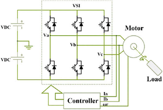
The surface-mounted permanent magnet synchronous motor (SPMSM) is very attractive type nowadays in drive systems for its numerous advantages such as, high efficiency, high torque to inertia ratio, high power density, reliability, and long life (Pandav et al., 2017a). In addition, the surface-mounted PMSM is preferred than the other type interior permanent magnet synchronous motor (IPMSM) because of its lower cost due to its simple rotor design (the permanent magnet (PM) material in SPMSM is mounted on the rotor, not inside the rotor as in the case of IPMSM). The motor-generator set is very spreading in most applications such as elevators, hybrid vehicles, and high-frequency machines (Hussien and Hassan, 2019). In the context of electric power generation and large fixed electrical power systems, a motor–generator consists of an electric motor mechanically coupled to an electric generator (or alternator) (Chokkalingam et al., 2019; Bharatiraja et al., 2017). The motor runs on the electrical input current while the generator creates the electrical output current, with power flowing between the two machines as a mechanical torque; this provides electrical isolation and some buffering of the power between the two electrical systems (Pandav et al., 2017b; Sanjeevikumar et al., 2016). In this paper, the motor-generator set can be arranged as using the SPMSM as the prime mover for a generator with doubly-fed type. For the motor side, the SPMSM is supplied with a voltage-source inverter (VSI) as given in Figure 1.
Power electronic converter acts as an interface between the electric generator and the utility grid to adjust the generator speed of the turbine. Hence, the converter rating has to be as same as that of the generator which consequently increases the overall system cost. In order to reduce the converter rating, the slip recovery machines can be used. The converter of these machines processes only the slip power in the rotor circuit resulting in a significant cost reduction compared to the full-capacity generating systems. These features have made the doubly-fed induction generators widely popular and attracting great attention from researchers (Xu et al., 2021).
Recently, Brushless Doubly-Fed Induction Machine (BDFIM) and the Brushless Doubly-Fed Reluctance Machine (BDFRM) have gained attention from researchers due to their self-cascaded arrangements (Xu et al., 2020). Although, both machines have common merits, the efficiency of the BDFRM is better than that of the BDFIM because of absence of rotor copper loss. Therefore, the Brushless Doubly-Fed Reluctance Generator (BDFRG) is preferable for variable-speed generating systems. Usually, BDFRG has two isolated windings arranged in the same fixed frame, i.e. the power winding (PW) and the control winding (CW). The PW is considered as the primary winding with a direct connection to the load/grid side. Furthermore, the CW is considered as the secondary winding which is generally connected through a bi-directional power electronic converter with the load/grid side (Chinthamalla et al., 2016; Hussien et al., 2022).
Different control techniques such as scalar control, vector control, and direct torque control are proposed for BDFRG. Out of various control strategies, the vector-control technique is preferred for high performance operation. The different techniques of vector control are mainly focused on the BDFRG rotor-position measurement aided with a rotor-position/speed encoder (Mousa et al., 2018). The required rotor position signal is needed to realize the desired angle of frame transformation for CW-side variables. The rotor-position/speed encoder increases cost and reliability problems which makes it undesirable in most drive systems. In recent years, sensorless vector-control strategies are adopted for estimation of rotor position/speed from the currents and voltages of the machine (Boldea et al., 2021; Kumar et al., 2019; Kumar and Das, 2018).
For an efficient operation of the adopted motor-generator set, this paper aims to apply the variable switching frequency PWM (VSFPWM) method for torque ripple control of the motor side (SPMSM). In addition, for the generator side (BDFRG), a new sensorless vector-control is applied and investigated for a high performance of the presented motor-generator system.
Torque Ripples Minimization Control for SPMSM
Prediction of Current Ripple
The prediction of ripple in current is described as follows (Fei Wang and Wang, 2014; Hussien et al., 2020; Jiang and Wang, 2013).
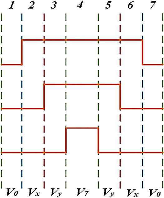
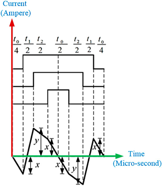
Aided with the SVPWM, Figure 2, the current ripple changes in each one cycle will considered as in Figure 3.
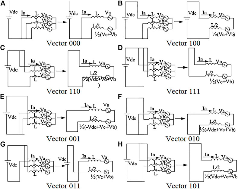
As shown in Figure 4, the slope of phase-A current is derived, during different zones, as
With the same principles, the slope of ripples for all phase currents can be given as in Table 1 (Hussien et al., 2020). The peak level of the slope can be given as in Eq. 7 with the values x and y to be plus or minus signs.

TABLE 1. Slope of current ripple for the three phases (Hussien et al., 2020).
Prediction of Torque Ripple
The relationship between current ripple and PWM torque ripple is given as (Fei Wang and Wang, 2014).
where,
where
The PWM torque ripple is obtained as
Then, the variable switching frequency PWM (VSFPWM) is attained based on the prediction process of torque ripple.
Torque Ripple Control-Based VSFPWM
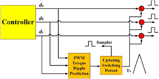
The criteria of torque ripple minimization used in this paper is specified in Figure 5. The switching period can be updated according to the following relation (Hussien et al., 2020).
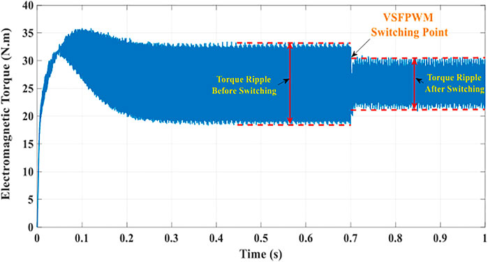
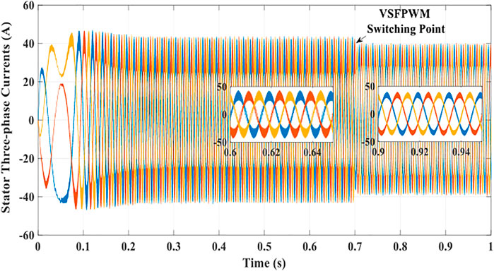
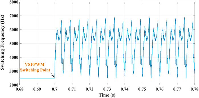
To assure the effectiveness of the proposed VSFPWM methodology for torque ripple minimization of the SPMSM drive system, some results are given in Figures 6–8.
The results ensure the controllability of the presented strategy to minimize the ripples of torque using VSFPWM for the SPMSM drives.
A New Sensolress Vector-Control Strategy of BDFIG Drive Systems
Dynamic Model of Generator
The complete modeling of BDFRG is presented in literature (Mousa et al., 2018) and briefly described as follows:
The power and control windings’ voltage equations in dq-axis and its flux linkage relations can be expressed as:
where
where
With respect to vector control, the electromagnetic torque can be expressed as follows:
Vector-Control Based PW Field-Orientation Method
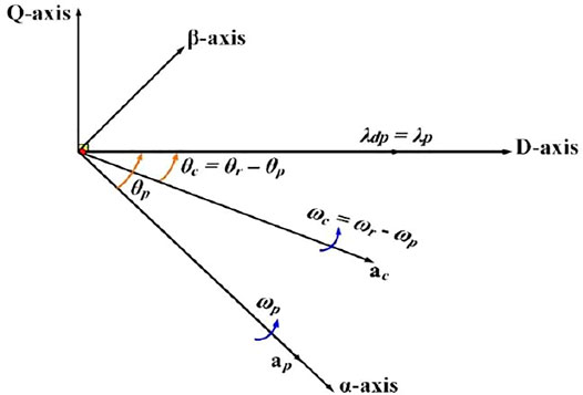
The principle advantage of the BDFRG vector-control strategy is the resultant decoupling effect between the electromagnetic torque and Qpower (Mousa et al., 2018). BDFRG vector control is based on the position of total power-winding’s flux vector,
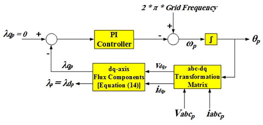
The block diagram of Phase-Locked Loop method used to estimate the flux vector magnitude of power-winding,
Primarily, angle
The angular frequency,
The torque and reactive power can be easily obtained from the proposed flux orientation of power-winding.
From Eqs. 17, 18, it is evident that, instantaneous electromagnetic torque and reactive-power control can be simply realized by controlling
Design Procedure of the Proposed Rotor Position Observer
BDFRG rotor position can be estimated using the following relation [21]:
where,
In (Mousa et al., 2018),
The main issue of this rotor-position estimation method is the integration of three-phase power-winding voltages to obtain the flux linkage using Eq. 20. This considers the main problem of the most sensorless drive systems especially at low speed conditions. In this paper, voltage-integration problem has been overcome by the proposed simple rotor-position estimation method which is outlined as:
Aided with the dq-axis components of the power-winding flux and its angle,
Then, the space-vector flux linkage is given by:
where the symbol “j” denotes the imaginary unit.
Based on Eq. 22, the space-vector power-winding flux linkage is estimated without voltage-integration. Hence, it can be simply used to estimate the BDFRG rotor-position using Eq. 19.
Stability Analysis of Proposed Position Observer
In this subsection, stability confirmation of proposed control system is clearly satisfied. Assuming that the proposed procedure initializes with an error between the position which is predicted, θr_est, and actual position, θr. Therefore, the actual d-q frame assigned on the αβ-axis PW stationary reference frame, used to obtain
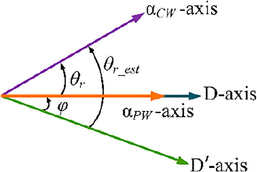
FIGURE 11. Corresponding fictitious frame transformations with the phase axis relationship of BDFRG considering the position error.
The rotor position’s estimation error is determined as φ = (θr_est - θr). Coupling component ΔicPW will be obtained in the q'-axis as a result of position error. Consequently, this term can be neglected by representing the φ = 0.
Based on the imaginary reference frame d′-q′ shown in Figure 11,
Therefore, aided with Eq. 19
The speed estimation error is considered to be
Then, derivative of position estimation error is as follows:
where Ko and Ki are the adopted sensorless system’s control parameters
where
with
It is dedicated that f(φ) is a continuous even function and f (0) = 1. Hence, the stability domain of Eq. 29 is projected to be symmetric at desired operating point, φ = 0.
Stability of large system signal is verified by using the multi-model to represent Eq. 29 as
For
From Eqs. 29, 30, it is evident that they are totally equivalent: approximation, linearization and simplification are not made. Also, considering that
The quadratic Lyapunov function is determined in order to validate the stability analysis Eq. 30, as
From the analysis, it is evident that the proposed control system, both (29) and (30), is stable by obtaining a symmetric matrix, N, attaining as follows
The convergence domain is obtained from maximum position error, φmax, related to linear matrix inequalities found in Eq. 34. From above relations, it is evident that the estimation of convergence domain can be concluded as 0 ≤ absolute(φ) ≤ 90. This proves that the theoretical convergence domain is the largest possible which validates the stability of the proposed sensorless position observer.
Results and Discussion
A sample of results is presented in this section to validate the proposed control technique. The analysis obtained are based on a six/two-pole, 4.5 kW BDFRG prototype. The overall system parameters are listed in (Mousa et al., 2018).
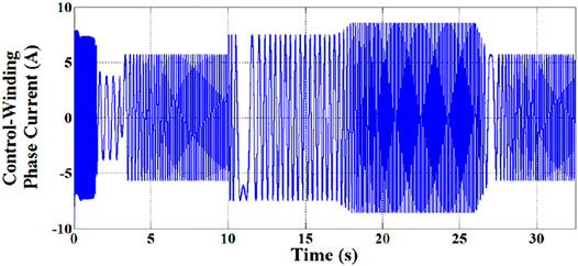
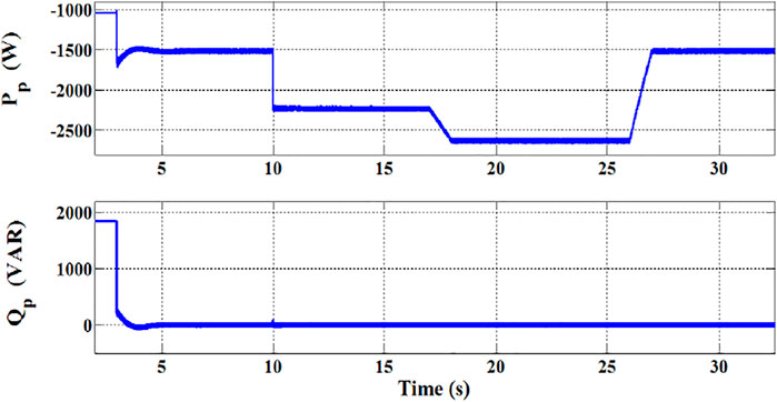
Initially up to 3 s, BDFRG is freely run with short-circuited CW terminals for the purpose of soft starting. Then, the partially power-rating converter is switched into the CW. The response of the CW phase-current during different periods corresponding to various wind speed is depicted in Figure 12. It is evident, that the over-current of converter is entirely prevented using the soft-starting method.
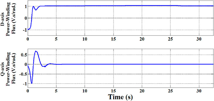
Figure 13 shows the response of dq-axis PW flux components. It is evident, that the q-axis component,
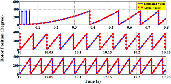
In addition, Figure 14 depicts the BDFRG estimated rotor-position and the corresponding actual value. It is evident that there is a close correlation between the estimated and actual rotor-position of the generator which validates the rotor-position estimation method of the proposed sensorless control technique.
Also, the dynamic response of active and reactive power of PW is depicted in Figure 15. It evident that the reactive power is maintained constant at zero which ensures a unity power-factor operation.
Conclusion
This paper has handled an effective method for reducing the ripples of torque using VSFPWM technique for the applications of SPMSM drives. In addition, a sensorless vector-control technique for BDFRG is proposed in this paper. The results have confirmed the controllability of the prediction process for torque ripple. Moreover, the proposed VSFPWM technique has achieved a good performance for the minimization target of torque ripple. In addition, a close correlation between the generator’s estimated and actual rotor-speed proves the efficacy of the proposed rotor-position/speed estimation method. Furthermore, the obtained results have assured the simplicity and capability of the presented simple sensorless observer of the adopted generator system.
Data Availability Statement
The original contributions presented in the study are included in the article/Supplementary Material, further inquiries can be directed to the corresponding author.
Author Contributions
All authors listed have made a substantial, direct, and intellectual contribution to the work and approved it for publication.
Conflict of Interest
The authors declare that the research was conducted in the absence of any commercial or financial relationships that could be construed as a potential conflict of interest.
Publisher’s Note
All claims expressed in this article are solely those of the authors and do not necessarily represent those of their affiliated organizations, or those of the publisher, the editors and the reviewers. Any product that may be evaluated in this article, or claim that may be made by its manufacturer, is not guaranteed or endorsed by the publisher.
Acknowledgments
The authors extend their appreciation to the Deanship of Scientific Research at King Khalid University for funding this work through General Research Project under Grant number (RGP.1/133/43).
References
Bharatiraja, C., Sanjeevikumar, P., Mahes, A., Saxena, A., Padmapriya, K., Mithra, B. K., et al. (2017). Analysis, Design and Investigation on a New Single-phase Switched Quasi Z-Source Inverter for Photovoltaic Application. International Journal of Power Electronics and Drive Systems 8 (2), 853–860. doi:10.11591/ijpeds.v8.i2.pp853-860
Boldea, I., Tutelea, L. N., Wu, C., Blaabjerg, F., Liu, Y., Hussien, M. G., et al. (2021). Fractional kVA Rating PWM Converter Doubly Fed Variable Speed Electric Generator Systems: An Overview in 2020. IEEE Access 9, 117957–117968. doi:10.1109/access.2021.3101907
Chinthamalla, R., Sanjeevikumar, P., Karampuria, R., Jain, S., and Ertas, A. H. (2016). Viliam Fedak, “A Solar PV Water Pumping Solution Using a Three-Level Cascaded Inverter Connected Induction Motor Drive”. Eng. Sci. Technol. Int. J. (JESTECH) 19 (4), 1731–1741.
Chokkalingam, B., Bhaskar, M. S., Padmanaban, S., Ramachandaramurthy, V. K., and Iqbal, A. (2019). Investigations of Multi-Carrier Pulse Width Modulation Schemes for Diode Free Neutral Point Clamped Multilevel Inverters. J. Power Electron. 19 (3), 702–713.
Fei Wang, D., and Wang, F. (2014) Current-Ripple Prediction for Three-phase PWM Converters,” IEEE Trans. Ind. Appl. 50 (1), 531–538. doi:10.1109/tia.2013.2270224
Hussien, M. G., and Hassan, A. E. “Mathematical Analysis of the Small Signal Model for Voltage-Source Inverter in SPMSM Drive Systems,” in Proceedings of the 2019 21st International Middle East Power Systems Conference (MEPCON), Cairo, Egypt, December 2019, 540–549. doi:10.1109/mepcon47431.2019.9008172
Hussien, M. G., Liu, Y., Xu, W., Junejo, A. K., and Allam, S. M. (2022). Improved MRAS Rotor Position Observer Based on Control Winding Power Factor for Stand-Alone Brushless Doubly-Fed Induction Generators. IEEE Trans. Energy Convers. 37 (1), 707–717. doi:10.1109/tec.2021.3110776
Hussien, M. G., Sanjeevikumar, P., Leonowicz, Z., Bo Holm-Nielsen, J., and Mihet-Popa, L. “Theoretical and Performance Analysis of PWM Control-Based Variable Switching Frequency for Torque Ripple Reduction in SPMSM Drive Systems,” in Proceedings of the 2020 IEEE International Conference on Environment and Electrical Engineering and 2020 IEEE Industrial and Commercial Power Systems Europe, Madrid, Spain, June 2020 (EEEIC/I&CPS Europe), 1–5.
Jiang, D., and Wang, F. (2013) Variable Switching Frequency PWM for Three-phase Converters Based on Current Ripple Prediction. IEEE Trans. Power Electron. 28 (11), 4951–4961. doi:10.1109/tpel.2013.2240701
Kumar, M., Das, S., and Kiran, K. (2019). Sensorless Speed Estimation of Brushless Doubly-Fed Reluctance Generator Using Active Power Based MRAS. IEEE Trans. Power Electron. 34 (8), 7878–7886. doi:10.1109/tpel.2018.2882473
Kumar, M., and Das, S. (2018). Model Reference Adaptive System Based Sensorless Speed Estimation of Brushless Doubly-Fed Reluctance Generator for Wind Power Application. IET Power Electron 11 (Issue 14), 2355–2366. doi:10.1049/iet-pel.2018.5344
Mousa, M. G., Allam, S. M., and Rashad, E. M. (2018). Maximum Power Extraction under Different Vector-Control Schemes and Grid-Synchronization Strategy of a Wind-Driven Brushless Doubly-Fed Reluctance Generator. ISA Trans. 72, 287–297. doi:10.1016/j.isatra.2017.10.005
Pandav, K. M., Mahajan, S. B., Sanjeevikumar, P., Badave, S. M., and Pachagade, R. (2017a). “2.4 kW Three-phase Inverter for Aircraft Application-Hardware Implementation.” in Lecture Notes in Electrical Engineering. (Singapore: Springer Journal Publications). doi:10.1007/978-981-10-4394-9_33
Pandav, K. M., Mahajan, S. B., and Sanjeevikumar, P. (2017b) “Frede Blaabjerg, “Three Phase Z-Source Multilevel Inverter System for Renewable Energy Application”,” in Proceedings of the Intl. Conf. on Renewable Energy and Resources, OMICS International Publishing, USA, July 2017, 24–25.
Sanjeevikumar, P., Bhaskar, M. S., Pandav, K. M., Pierluigi, S., and Valentin, O. (2016) “Hexuple-Inverter Configuration for Multilevel Nine-phase Symmetrical Open- Winding Converter,” in Conf. Proc., Proceedings of the IEEE First Intl. Conf. Power Electron., Intelligent Control and Energy System, IEEE-ICPEICES’16, India, July 2016, 1837–1844.
Xu, W., Hussien, M. G., Liu, Y., and Allam, S. M. (2021). Sensorless Control of Ship Shaft Stand-Alone BDFIGs Based on Reactive-Power MRAS Observer. IEEE J. Emerg. Sel. Top. Power Electron. 9 (2), 1518–1531. doi:10.1109/jestpe.2019.2963264
Keywords: SPMSM, ripple prediction of torque, VSFPWM, BDFRG, sensorless vector-control
Citation: Hussien MG, Salem Elbarbary ZM and Hassan AE-W (2022) High-Performance Sensorless Operation of Motor-Generator Set With an Improved Torque-Ripple Minimization Strategy. Front. Energy Res. 10:870850. doi: 10.3389/fenrg.2022.870850
Received: 07 February 2022; Accepted: 19 April 2022;
Published: 30 May 2022.
Edited by:
Nallapaneni Manoj Kumar, City University of Hong Kong, Hong Kong SAR, ChinaReviewed by:
Mukesh Kumar, Indian School of Mines, IndiaNarottam Das, Central Queensland University, Australia
Tian-Hua Liu, National Taiwan University of Science and Technology, Taiwan
Copyright © 2022 Hussien, Salem Elbarbary and Hassan. This is an open-access article distributed under the terms of the Creative Commons Attribution License (CC BY). The use, distribution or reproduction in other forums is permitted, provided the original author(s) and the copyright owner(s) are credited and that the original publication in this journal is cited, in accordance with accepted academic practice. No use, distribution or reproduction is permitted which does not comply with these terms.
*Correspondence: Mohamed G. Hussien, bW9oYW1lZC5odXNzaWVuM0BmLWVuZy50YW50YS5lZHUuZWc=
 Mohamed G. Hussien
 Zakaria M. Salem Elbarbary2,3