- 1School of Electrical and Electronic Engineering, Shandong University of Technology, Zibo, China
- 2Construction Branch of State Grid Jiangsu Electric Power Co., Ltd, Nanjing, China
The flexible graphite composite grounding electrode is a non-metallic grounding electrode with good electrical conductivity, corrosion resistance and non-ferromagnetic properties. In order to analyze the impulse characteristics of the graphite composite grounding electrode, this paper builds a frequency domain electrical network model and an equivalent radius iterative algorithm, considering skin effect, inductance effect, capacitance effect and spark discharge effect. The impulse characteristics of typical metal grounding electrodes and graphite composite grounding electrodes are analyzed by simulation. The research results show that: Compared with the traditional metal grounding electrode, the graphite composite grounding electrode has a smaller skin and inductance effect under the action of the impulse current, and a better current flowing capability; as the soil resistivity increases, the inductance effect and the skin effect are weakened, while the spark discharge effect is gradually enhanced and dominates. The spark discharge effect can effectively decrease the grounding resistance. The obtained critical value of the normalized parameter of 412 kA Ω, can be taken as the threshold to discriminate the conditions with dominate inductance effect from the conditions with dominant spark discharge effect.
Introduction
The grounding grid is the most basic lightning protection device in power system. Good impulse grounding performance is an important prerequisite for ensuring safe and reliable operation of power system. The grounding resistance of grounding device generated by lightning current is called impulse grounding impedance (Deng et al., 2013; He and Zhang, 2015; Zhang, 2018). Different from the power frequency current, the lightning current flows through the grounding electrode in a pulse manner in a very short time, resulting in that the impulse grounding impedance is different from the power frequency grounding resistance (Grcev, 2009a) (Tao et al., 2018). The lightning current flowing through grounding electrode and soil is a complex electromagnetic transient process accompanied by various physical effects such as inductance effect and spark discharge effect (Grcev, 2009b; Visacro and Rosado, 2009; Deng et al., 2012; Wen et al., 2016). The CDEGS, an international general grounding simulation software, can be used to calculate the impulse grounding impedance of grounding electrode. However, the calculation results of CDEGS do not consider the influence of soil ionization, which is called spark discharge effect in this paper, leading to a large error between the calculation results and the actual grounding impedance of the grounding electrode (Yang et al., 2021; Feng et al., 2015). At present, the numerical simulation algorithms for impulse characteristics of grounding devices considering the effect of soil spark discharge mainly include transmission line modeling method (TLM) and finite element method (FEM). The impulse response of grounding devices using TLM is equivalent to the wave propagation of transmission line. This method cannot consider the coupling between conductors (de Lima and Portela, 2007; Gazzana et al., 2014). The FEM method is more efficient, but the change of soil resistivity will lead to the occurrence of ill-conditioned matrix in the calculation, thus affecting the calculation accuracy (Nekhoul et al., 1996). It is difficult to consider all the physical processes like skin effect, inductance effect and spark discharge process when impulse current flew through the grounding electrode.
In recent years, flexible graphite composite grounding material as a new type of non-magnetic grounding electrode has been applied to the grounding grids of power system (Huang et al., 2019; Hu et al., 2014). Compared with traditional metal grounding materials, flexible graphite composite grounding materials have good electrical conductivity and natural corrosion resistance (Gong et al., 2016; Hu et al., 2016; Xiao et al., 2017). In order to study the impulse characteristics of graphite composite grounding electrode under the influence of skin effect, inductance effect and capacitance effect, the frequency domain electrical network model is established by MATLAB to simulate the current flow process of tower grounding electrode. Moreover, the iterative algorithm of equivalent radius is used to consider the influence of soil nonlinear ionization around the grounding electrode. The influences of various physical effects on the impulse characteristics of graphite composite grounding electrode are obtained by simulation. The research results can provide theoretical reference for optimizing the length of graphite composite grounding electrode.
Simulation Modeling Method
Frequency Domain Electrical Network Model of Grounding Electrode
In this section, the impulse process of grounding electrode in Earth is considered by frequency domain electrical network model. A simple horizontal grounding electrode is applied. In order to describe the grounding electrode more intuitively, this paper adopts the circuit modeling with lumped parameters. Firstly, the grounding electrode is gridded and each segment is equivalent to a circuit model composed of resistance, inductance, grounding capacitance and grounding conductance (Mentre and Grcev, 1994) (Lorentzou et al., 2003). The equivalent electrical network model of horizontal grounding rod is shown in Figure 1.
Suppose there are a total of r branches, n nodes, so that the branches i = 1, 2, ···, r, nodes j = 1, 2, ···, n, where Ri, Li, Mi, Ci and Gi are the resistance, self-inductance, mutual-inductance, grounding capacitance, and grounding conductance of each branch after the grounding electrode meshing;
Assuming that the GPR of each segment of the branch is equal to the average value of the GPR at both ends, as shown in Eq. 1.
According to Eq. 1, the matrix relation between GPR vector
where K is the relationship matrix between the branch and the node. When branch i is associated with node j, the corresponding value is 0.5, otherwise the value is 0.
Assuming that the current distribution on each branch is uniform, and the current at each node is equal to the average value of the branch current connected to it. Similarly, the vector relation of the current flowing into the Earth on nodes and branches can be obtained, as shown in Eq. 3.
where K T is the transposed matrix of K.
The vector
where Z is the impedance matrix of conductor grounding branch. The elements in Z are composed of the self-impedance of each branch and the mutual impedance between branches.
Inverse matrix Z and get Eq. 5.
According to the node voltage equation, Eq. 6 is obtained.
where
Eq. 7 can be obtained by Eqs 2, 3, 5, and 6.
According to Eq. 7, the vector
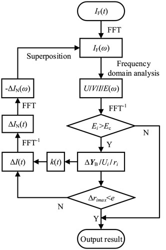
It is required to solve the impulse response curve of grounding electrode in the time domain. Firstly, the pulse current in the time domain is decomposed into a plurality of sinusoidal alternating currents with different frequencies by fast Fourier transform (FFT). Under the action of current with different frequencies, the corresponding branch admittance matrix
Iterative Algorithm Considering Spark Discharge Effect
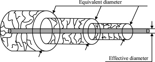
In order to consider the influence of spark discharge effect on the impulse characteristics of grounding electrode, it is assumed that the spark discharge area generated around each branch of the grounding electrode is a cylinder with uniform ionization. The equivalent model of grounding electrode during discharge is shown in Figure 2 (Shen and Raksincharoensak, 2021a; Shen and Raksincharoensak, 2021b).
Under the influence of sinusoidal alternating current at different frequencies, the grounding electrode surface and the surrounding soil will produce different electric field intensities
where ρ is the soil resistivity; ω is the angular frequency of the sinusoidal alternating current; ε is the dielectric constant of the soil.
The current density of the grounding electrode surface can be determined by the branch current flowing into the Earth. According to Eq. 8, the relationship between the electric field intensity Ei (ω) and the equivalent radius r of spark discharge can be obtained as shown in Eq. 9 (Shen et al., 2022).
The instantaneous value of electric field intensity in time domain is calculated by inverse Fourier transform of soil electric field intensity Ei (ω) around grounding electrode in frequency domain. By simplifying, the relationship between the equivalent radius
where
With the change of equivalent radius
Verification of Simulation Results
In order to verify the effectiveness of the frequency domain electrical network model and its iterative algorithm simulation results, the calculation results of this paper are compared with the calculation results of CDEGS grounding simulation software and the experimental results in the literature. Both simulations and experiments adopt round steel grounding electrodes. The grounding electrode radius is 10 mm, the length of grounding electrode is 20 m, the buried depth is 0.8 m, the impulse current waveform is 2.6/50 μs, the amplitude is 10 kA, the relative dielectric constant of sold is 9, and the soil critical breakdown field strength Ec is 400 kV/m (Mousa, 1994).
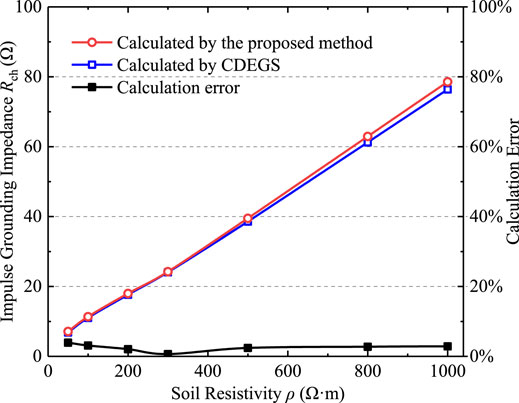
Without considering the effect of spark discharge, the variation curve of impulse grounding impedance Rch of grounding electrode under different soil resistivities is obtained by frequency domain electrical network model simulation. The calculation results are compared with the simulation results of CDEGS, as shown in Figure 4.
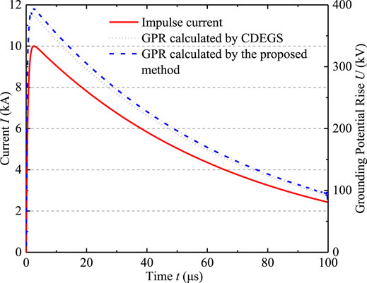
The simulation results in this paper are basically consistent with the laws of CDEGS calculations, and the maximum error is less than 4%. Figure 5 shows the time-domain voltage response curve of the grounding electrode when the soil resistivity ρ is 500 Ω m. It can be seen that the proposed method has good consistency with the calculation results of CDEGS, indicating that the calculation method of frequency domain electrical network model proposed in this paper is correct.
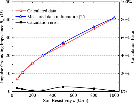
Moreover, this paper uses the equivalent radius iterative algorithm to simulate the soil discharge process, and compares its calculation results with the simulation results in literature (He et al., 2003), as shown in Figure 6. Affected by different soil resistivity, the impulse grounding impedance calculated by the equivalent radius iterative algorithm proposed in this paper is similar to the simulation experiment in literature (He et al., 2003), and the maximum error is less than 6%.
The calculated results of 20 m horizontal grounding electrode in soil with resistivity of 1,000 Ω m are compared with the results obtained from the full-scale experiments by Wen et al (Yang et al., 2022) in Table 1, where α is the impulse coefficient, which is equal to the ratio of impulse grounding impedance Rch to power frequency grounding resistance Rg. It can be seen that the calculated results are in good agreement with the experiment results of Wen et al (Yang et al., 2022). In general, the proposed simulation models and algorithms are correct, and the results are credible.
Effect of Various Physical Effects on Impulse Characteristics of Graphite Composite Grounding Electrodes
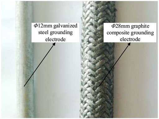
Under the action of high frequency lightning current and fault current, the grounding grid presents impedance characteristics, including resistance component and reactance component. Therefore, in order to analyze the grounding characteristics of graphite composite grounding materials, the grounding impedance characteristics should be analyzed under the action of alternating current. The physical processes affecting the grounding impedance include skin effect, inductance effect, capacitance effect and spark discharge effect. In this paper, the influence of four physical effects on graphite composite grounding materials is analyzed and calculated. The results are compared with traditional metal grounding materials (galvanized steel). The physical picture and measured parameters of grounding electrode of two materials are shown in Figure 7 and Table 2.
In the simulation, the length of grounding electrode is 10, 30, 60 m, the buried depth is 0.8m, the critical breakdown field strength of soil is 400 kV/m, the lightning current parameter is 2.6/50 μs, and the amplitude is 30 kA. In Table 2, Φ is the diameter of grounding electrode; δ is the grounding material resistivity, Ω·m; εr is the relative permeability of grounding material.
Capacitance Effect
When only capacitance effect is considered, inductance effect, skin effect and spark discharge effect should be ignored. That is, in the simulation calculation process, the grounding electrode inductance, high frequency resistance and iterative algorithm are not involved in the simulation calculation. The
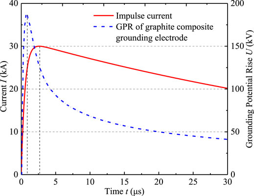
The capacitance effect will not only reduce the impulse grounding impedance, but also cause the grounding potential rise waveform on the grounding electrode lagging behind the impulse current waveform. Figure 8 shows the impulse current waveform and grounding potential rise waveform of graphite composite grounding electrode with soil resistivity ρ of 4,000 Ω m and length l of 10 m.
Skin Effect
Finite element numerical calculation method is used to compare and analyze the skin effect of grounding electrodes of different materials in the flow of high frequency current. Galvanized steel grounding electrode of diameter Φ = 12 mm and graphite composite grounding electrode of diameter Φ = 28 mm are applied during simulation according to practical grounding engineering. The current frequency is 100 kHz, and the length l of grounding electrode is 1 m. The simulation results are shown in Figure 9.

FIGURE 9. Skin effect of grounding electrodes. (A) Current density of Φ12 mm galvanized steel grounding electrode cross section. (B) Current density of Φ28 mm graphite composite grounding electrode cross section.
It can be seen that the current density distribution of galvanized steel grounding electrode is extremely uneven due to skin effect, and the current is mostly concentrated on the external surface of the grounding electrode. This results in a significant reduction in the actual area of current flowing through the grounding electrode. On the contrary, the current density distribution of graphite composite grounding electrode is relatively uniform.
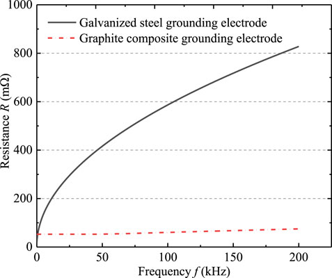
Due to the influence of high frequency current, the cross-sectional area of the actual current flowing through the grounding electrode decreases, thereby increasing the resistance of the grounding electrode. In order to compare and analyze the influence of skin effect on the grounding characteristics of two grounding materials, the resistance R of grounding electrode under different frequencies is used as the influencing factor of skin effect, which can be calculated according to Eq. 11.
where σ is the conductivity of the conductor; δ is the radial depth that the current flowing through the grounding electrode can reach due to the skin effect, and is calculated by Eq. 12.
where μ0 is vacuum permeability; μr the relative permeability of grounding material. The actual lightning current frequency is mostly concentrated in 0–200 kHz. The resistance R of graphite composite grounding electrode and galvanized steel grounding electrode in the unit length can be obtained by calculation. As shown in Figure 10, as the frequency increases, the resistance R of galvanized steel grounding electrode increases greatly. In contrast, the increase in resistance of graphite composite grounding electrode is small, which indicates that the graphite composite grounding electrode has less affected by the skin effect under the action of high frequency current.
Considering the capacitance effect, the impulse coefficient αsc and αc of the grounding electrode at different materials are calculated with and without the skin effect. In order to facilitate the analysis of the influence of skin effect on the grounding electrode impulse characteristics, the influence rate ηs of skin effect on the impulse coefficient is defined. The effect of skin effect on the impulse characteristics of grounding electrode can be solved by Eq. 13.
The effect rate of skin effect on the grounding electrodes is shown in Table 3. It can be seen that the change of impulse coefficient of galvanized steel grounding electrode is greater than that of graphite composite grounding electrode affected by lightning current. The influence of graphite composite grounding electrode is less than 1%.
On the whole, the resistance R of the grounding electrode is related to its length l, and the longer the length l, the larger the resistance R. Therefore, when the length of the grounding electrode is long, the skin effect has a great influence. In high soil resistance area, the lightning grounding current flows through the grounding electrode, and the current flowing to the surrounding soil is small, resulting in large impulse grounding impedance. At this time, the proportion of GPR of grounding electrode in the total GPR is small, so the skin effect is weak.
Inductance Effect
In order to fully consider the influence of the inductance effect, this paper divides the inductance of the grounding electrode into self-inductance and mutual inductance, and the mutual inductance can be obtained by the Neumann equation (Ma et al., 2015). Since the magnetic flux generated by the current through the conductor is respectively closed inside and outside the conductor, the self-inductance is equal to the sum of external self-inductance and inner self-inductance. The external self-inductance Le can ignore the influence of frequency and it is calculated by Eq. 14.
where μ0 is vacuum permeability; l is the length of grounding electrode; r is the radius of the grounding electrode. The internal self-inductance Li is calculated by the low frequency current, as shown in Eq. 15.
where μ0 is vacuum permeability; μr the relative permeability of grounding material; l is the length of grounding electrode. When the current frequency is high, the internal self-inductance of grounding electrode changes due to skin effect, and is solved according to Eq. 16.
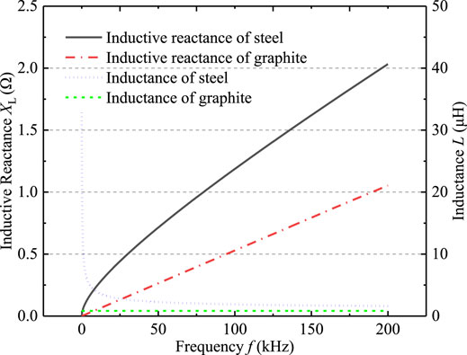
where μ0 is vacuum permeability; μr the relative permeability of grounding material; l is the length of grounding electrode; r is the radius of the grounding electrode; σ is the conductivity of the grounding electrode. As the sinusoidal alternating current at different frequencies changes, the self-inductance and inductive reactance per unit length of graphite composite grounding electrode and galvanized steel grounding electrode are shown in Figure 11.
Under the influence of 0–200 kHz AC current, the inductive reactance of graphite composite grounding electrode is smaller than that of galvanized steel grounding electrode. This is because the galvanized steel grounding electrode is the paramagnetic material, and its magnetic permeability is much larger than that of the graphite composite grounding electrode, resulting in a larger inductance of galvanized steel grounding electrode.
Considering the capacitance effect, skin effect and inductance effect simultaneously, the impulse coefficient αSLC of grounding electrode is calculated, and the influence rate ηL of inductance effect is obtained by Eq. 17.
As shown in Table 4, the galvanized steel grounding electrode is more affected than graphite composite grounding electrode due to the inductance effect. Overall, the longer the length l of grounding electrode, the stronger the inductance effect, and the greater the obstruction of current flowing to the far position of grounding electrode. With the increase of soil resistivity, the proportion of GPR generated by the inductance of grounding electrode in total GPR decreases. Therefore, the inductance effect of grounding electrode has little effect on its impulse grounding characteristics in the areas with high soil resistivity.
Without considering the spark discharge effect, the variation of impulse coefficient of calculated graphite composite grounding electrode with soil resistivity is shown in Figure 12. In most cases, the impulse coefficient αSLC is greater than the value 1. As skin effect has little effect on graphite composite grounding material, it is mainly caused by the inductive effect of grounding electrode. Figure 13 shows the impulse response curve when the soil resistivity ρ is 50 Ω m and the grounding electrode length l is 60 m. It can be seen that the grounding impedance of grounding electrode presents inductance characteristics, and the GPR waveform is ahead of the impulse current. When the grounding electrode is short or the soil resistivity is high, the impulse coefficient αSLC appears to be less than the value 1. This is because the conductivity of soil is poor, and the influence of inductance effect and skin effect are small. At this time, the grounding capacitance of grounding electrode is involved in the diffusion of high frequency current, resulting in significant capacitance characteristic of impulse grounding impedance, and the impulse grounding impedance is less than power frequency grounding resistance.
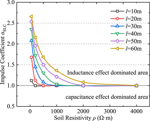
FIGURE 12. Impulse coefficient of graphite composite grounding electrode without spark discharge effect.
Spark Discharge Effect
Under the effect of the impulse current, when the electric field intensity E of the soil around the grounding electrode reaches the critical breakdown electric field intensity Ec of the soil, the soil ionization occurs due to the breakdown. The soil resistivity around the grounding electrode is greatly reduced. An iterative algorithm of equivalent radius of grounding electrode is used to simulate the spark discharge process and calculate the impact grounding impedance of grounding electrode. The influence rate ηD of spark discharge effect is calculated by Eq. 18, as shown in Table 5 and Table 6.
Where the impulse coefficient αSLC considering capacitance effect, skin effect and inductance effect; the impulse coefficient α considering capacitance effect, skin effect, inductance effect and spark discharge. The spark discharge effect of galvanized steel grounding electrode is slightly better than that of graphite composite grounding electrode, but graphite composite grounding electrode is less affected by inductance effect and skin effect, so it has better current flowing capability. Comparing the impulse grounding impedance, the inductance effect is less affected when the soil resistivity is high and the grounding electrode length is short, and the galvanized steel grounding electrode is greatly affected by the spark discharge effect, resulting in its impulse grounding impedance Rch is smaller than graphite. But as a whole, the impulse grounding impedance of graphite composite grounding electrode is mostly smaller than that of steel. In the actual engineering design of tower grounding engineering, large-size square grounding electrodes with elongated conductors are usually used. The grounding electrode is more affected by inductance effect and skin effect. Therefore, the impulse grounding characteristic of graphite composite grounding electrode is better than that of galvanized steel grounding electrode.
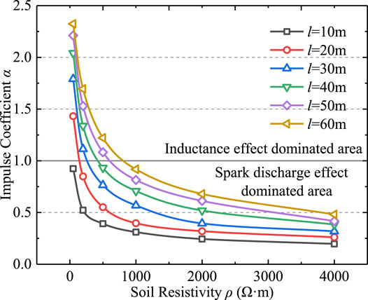
In summary, the inductance effect and skin effect will increase the grounding impedance of the grounding electrode. Conversely, the capacitance effect and sparking discharge effect can reduce the impulse grounding impedance. For graphite composite grounding electrode, the capacitance effect and skin effect have little effect, so this paper only analyzes the influence of inductance effect and spark discharge effect. It can be seen from Figure 14 that in the low soil resistivity area and the grounding electrode is long, the grounding electrode impulse coefficient α is greater than the value 1. The GPR generated by inductance effect accounts for a large proportion of the total GPR, leading to the inductance effect being dominant. However, as the soil resistivity ρ increases, the impulse coefficient α decreases and the spark discharge effect increases. When α is less than the value 1, the spark discharge effect is more dominant than inductance effect.
Optimization of Length of Flexible Graphite Composite Grounding Electrode
In practical engineering applications, in order to improve the current dispersion characteristics of tower grounding grid, the effect of inductance effect should be minimized or the effect of spark discharge effect should be increased to make the spark discharge effect of grounding electrode dominant. According to the field measurement results of lightning current, this paper selects three kinds of the most common lightning current, the waveforms are shown in Table 7.
Waveform 1 is a typical initial waveform of lightning impulse current, which is mainly used to simulate the significant inductance effect. Waveform 2 is the standard lightning current waveform recommended for lightning protection calculation. Waveform 3 is a typical secondary waveform of lightning impulse current, which is mainly used to simulate the significant spark discharge effect.
The impulse coefficient α of graphite composite grounding electrode is calculated under different lightning current waveforms.
According to the fitting of the result curve, the soil resistivity critical value ρc was estimated, which is the soil resistivity when the pulse characteristic is converted from the dominance of inductance effect to the dominance of spark discharge effect. As shown in Table 8, the inductance effect dominates when the soil resistivity is less than the corresponding critical value, otherwise the spark discharge effect dominates.

TABLE 8. Soil resistivity critical value on which dominant inductance effect switch to spark discharge effect.
In order to facilitate the optimal design of grounding electrode, it is necessary to make a general quantitative description of the dominant range of inductance effect and spark effect. Therefore, the normalization parameter S is defined as the quantitative criterion of conversion, which can be calculated by Eq. 19.
According to Table 9, when the soil resistivity ρ and the lightning impulse current front waveform time T1 and the peak value Im are known, the appropriate grounding electrode length l can be selected to ensure that the impulse characteristics are always dominated by spark discharge effect, so as to reduce the impulse impedance. For example, when the soil resistivity ρ is 500 Ω m and the lightning current is waveform 2, the grounding electrode length l is selected as 40 m, and the corresponding normalized parameter S is 375 kA Ω, which is larger than the 321 kA Ω in Table 9. The spark discharge effect dominates, and the impulse grounding impedance Rch is smaller than the power frequency grounding resistance Rg. Meanwhile, in order to facilitate engineers to conservatively estimate the impulse characteristics of graphite composite grounding electrode, the maximum value of 412 kA Ω in Table 9 is taken as the critical value of normalized parameter for converting inductance effect into spark discharge effect. It should be pointed out that the above conclusion is determined according to the soil critical breakdown field strength Ec of 400 kV/m, which has a certain deviation from the actual Ec value. When Ec>400 kV/m, the corresponding normalized parameter S is larger than the values listed in Table 9, and when Ec<400 kV/m, S is smaller than the values in Table 9.

TABLE 9. Critical value of normalized parameters on which dominant inductance effect switch to dominant spark discharge effect.
Conclusion
This paper presents a frequency domain electrical network analysis method to simulate the impulse characteristics of grounding electrodes. The impulse characteristics of typical metal grounding electrode and graphite composite grounding electrode are calculated, and the following conclusions are obtained.
1) Compared with the galvanized steel grounding electrode, the graphite composite grounding electrode has little effect on skin effect and inductance effect, and the graphite composite grounding electrode has better current dispersion ability under the impulse current.
2) The inductance effect and skin effect can increase the grounding impedance of grounding electrode, while the capacitance effect and spark discharge effect can reduce it. However, the capacitance effect is very small compared with the spark discharge effect, which can be ignored.
3) The longer the grounding electrode length, the more obvious the effect of inductance and skin effect. However, with the increase of soil resistivity, the influence of the two decreases, and the spark discharge effect increases and gradually dominates.
4) The normalized parameter S is defined to quantitatively distinguish the influence range of inductance effect and spark discharge effect. The length of graphite composite grounding electrode can be optimized by critical value S, so as to ensure that the impulse characteristics are always dominated by spark effect, and finally the purpose of reducing impulse grounding impedance is achieved. To conservatively estimate the impulse characteristics of grounding electrode, the recommended S value is 412 kA Ω as the critical value to convert inductive effect into spark discharge effect (Shen and Raksincharoensak, 2021b).
Data Availability Statement
The original contributions presented in the study are included in the article/Supplementary Material, further inquiries can be directed to the corresponding author.
Author Contributions
YH: conceptualization, writing-original draft preparation, software; TH: software; YA: funding acquisition, validation; JF: Simulation and figures; MC: project administration; HX: supervision; WS: supervision; CD: validation.
Funding
This manuscript was supported in part by the Natural Science Foundation of China under Grant 51807113, in part by the Natural Science Foundation of Shandong Province under Grant ZR202103040796 and the Natural Science Foundation of Jiangsu Province under Grant SBK2020042717.
Conflict of Interest
TH, MC, HX, WS and CD are employed by Construction Branch of State Grid Jiangsu Electric Power Co., Ltd.
The remaining authors declare that the research was conducted in the absence of any commercial or financial relationships that could be construed as a potential conflict of interest.
Publisher’s Note
All claims expressed in this article are solely those of the authors and do not necessarily represent those of their affiliated organizations, or those of the publisher, the editors and the reviewers. Any product that may be evaluated in this article, or claim that may be made by its manufacturer, is not guaranteed or endorsed by the publisher.
References
de Lima, A. C. S., and Portela, C. (2007). Inclusion of Frequency-dependent Soil Parameters in Transmission-Line Modeling. IEEE Trans. Power Deliv. 22 (1), 492–499. doi:10.1109/tpwrd.2006.881582
Deng, C., Yang, Y., Tong, X., Dong, X., and Peng, Q. (2012). Impulse Characteristics Analysis of Grounding Devices. High Voltage Eng. 38 (9), 1–8. doi:10.3969/j.issn.1003-6520.2012.09.044
Deng, C., Yang, Y., Dong, X., Ma, S., Peng, Q., and Wang, X. (2013). Development of Impulse High Current Testing System of Grounding Devices and Testing of tower Grounding Impulse Characteristics. High Voltage Eng. 39 (6), 1527–1535. doi:10.3969/j.issn.1003-6520.2013.06.035
Feng, Z., Wen, X., Tong, X., Lu, H., Lan, L., and Xing, P. (2015). Impulse Characteristics of Tower Grounding Devices Considering Soil Ionization by the Time-Domain Difference Method. IEEE Trans. Power Deliv. 30 (4), 1906–1913. doi:10.1109/tpwrd.2015.2425419
Gazzana, D. S., Bretas, A. S., Dias, G. A. D., Telló, M., Thomas, D. W. P., and Christopoulos, C. (2014). The Transmission Line Modeling Method to Represent the Soil Ionization Phenomenon in Grounding Systems. IEEE Trans. Magn. 50 (2), 103–107. doi:10.1109/tmag.2013.2283714
Gong, R., Ruan, J., Hu, Y., Wu, Y., and Jin, S. (2016). “Research on Flexible Graphite-Copper Composited Electrical Grounding Material,” in Proceeding of the 12th IET International Conference on AC and DC Power Transmission (ACDC 2016), Beijing, China (IEEE), 1–6. doi:10.1049/cp.2016.0403
Grcev, L. (2009). Time- and Frequency-dependent Lightning Surge Characteristics of Grounding Electrodes. IEEE Trans. Power Deliv. 24 (4), 2186–2196. doi:10.1109/tpwrd.2009.2027511
Grcev, L. (2009). Impulse Efficiency of Ground Electrodes. IEEE Trans. Power Deliv. 24 (1), 441–451. doi:10.1109/tpwrd.2008.923396
He, J., Zeng, R., Tu, Y., Zou, J., Guan, S., and Guan, Z. (2003). Laboratory Investigation of Impulse Characteristics of Transmission tower Grounding Devices. IEEE Trans. Power Deliv. 18 (3), 994–1001. doi:10.1109/tpwrd.2003.813802
He, J., and Zhang, B. (2015). Progress in Lightning Impulse Characteristics of Grounding Electrodes with Soil Ionization. IEEE Trans. Ind. Applicat. 51 (6), 4924–4933. doi:10.1109/tia.2015.2427124
Hu, Y., An, Y., Xian, R., Li, H., Ruan, J., Huang, D., et al. (2016). “Study on Magnetic Properties of Flexible Graphite Composite Grounding Material,” in Proceeding of the 2016 IEEE International Conference on High Voltage Engineering and Application, Chengdu, China, Sept. 2016 (IEEE), 1–4. doi:10.1109/ICHVE.2016.7800753
Hu, Y., Ruan, J., Gong, R., Liu, Z., Wu, Y., and Wen, W. (2014). Flexible Graphite Composite Electrical Grounding Material and its Application in tower Grounding Grid of Power Transmission System. Power Syst. Technol. 38 (10), 2851–2857. doi:10.13335/j.1000-3673.pst.2014.10.037
Huang, D., Xia, J., Ruan, J., Wu, Y., and Quan, W. (2019). Characteristics of the Flexible Graphite Grounding Material and its Engineering Application. IEEE Access 7, 59780–59787. doi:10.1109/access.2019.2913558
Lorentzou, M. I., Hatziargyriou, N. D., and Papadias, B. C. (2003). Time Domain Analysis of Grounding Electrodes Impulse Response. IEEE Trans. Power Deliv. 18 (2), 517–524. doi:10.1109/tpwrd.2003.809686
Ma, Z., Zhou, X., Shang, Y., and Zhou, L. (2015). Form and Development Trend of Future Distribution System. Proc. CSEE 35 (6), 1289–1298. doi:10.13334/j.0258-8013.pcsee.2015.06.001
Mentre, F. E., and Grcev, L. (1994). EMTP-based Model for Grounding System Analysis. IEEE Trans. Power Deliv. 9 (4), 1838–1849. doi:10.1109/61.329517
Mousa, A. M. (1994). The Soil Ionization Gradient Associated with Discharge of High Currents into Concentrated Electrodes. IEEE Trans. Power Deliv. 9 (3), 1669–1677. doi:10.1109/61.311195
Nekhoul, B., Labie, P., Zgainski, F. X., Meunier, G., Morillon, F., and Bourg, S. (1996). Calculating the Impedance of a Grounding System. IEEE Trans. Magn. 32 (3), 1509–1512. doi:10.1109/20.497536
Shen, X., Ouyang, T., Khajorntraidet, C., Li, Y., Li, S., and Zhuang, J. (2022). Mixture Density Networks-Based Knock Simulator. Ieee/asme Trans. Mechatron. 27, 159–168. doi:10.1109/TMECH.2021.3059775
Shen, X., and Raksincharoensak, P. (2021a). Pedestrian-aware Statistical Risk Assessment. IEEE Trans. Intell. Transport. Syst., 1–9. doi:10.1109/TITS.2021.3074522
Shen, X., and Raksincharoensak, P. (2021b). Statistical Models of Near-Accident Event and Pedestrian Behavior at Non-signalized Intersections. J. Appl. Stat., 1–21. doi:10.1080/02664763.2021.1962263
Tao, S., Zhang, X., Wang, Y., and Yang, J. (2018). Transient Behavior Analysis of Offshore Wind Turbines during Lightning Strike to Multi-Blade. IEEE Access 6, 22070–22083. doi:10.1109/access.2018.2828043
Visacro, S., and Rosado, G. (2009). Response of Grounding Electrodes to Impulsive Currents: An Experimental Evaluation. IEEE Trans. Electromagn. Compat. 51 (1), 161–164. doi:10.1109/temc.2008.2008396
Wen, X., Feng, Z., Lu, H., Tong, X., Lan, L., Chen, W., et al. (2016). Sparkover Observation and Analysis of the Soil under the Impulse Current. IET Sci. Meas. Tech. 10 (3), 228–233. doi:10.1049/iet-smt.2015.0082
Xiao, W., Hu, Y., Ruan, J., Zhan, Q., and Huang, D. (2017). Flexible Graphite Composite Electrical Grounding Material and its Grounding Application Features. Power Syst. Technol. 32 (2), 85–94. doi:10.19595/j.cnki.1000-6753.tces.2017.02.010
Yang, N., Yang, C., Xing, C., Ye, D., Jia, J., Chen, D., et al. (2021). Deep Learning‐based SCUC Decision‐making: An Intelligent Data‐driven Approach with Self‐learning Capabilities. IET Generation Trans. Dist 16, 629–640. doi:10.1049/gtd2.12315
Yang, N., Yang, C., Wu, L., Shen, X., Jia, J., Li, Z., et al. (2022). Intelligent Data-Driven Decision-Making Method for DynamicMultisequence: An E-Seq2Seq-Based SCUC Expert System. IEEE Trans. Ind. Inf. 18, 3126–3137. doi:10.1109/TII.2021.3107406
Keywords: power system grounding electrode, graphite composite grounding electrode, impulse characteristics, spark discharge effect, inductance effect, electrical network model
Citation: Hu Y, Huang T, An Y, Feng J, Cheng M, Xie H, Shen W and Du C (2022) Simulation Study on Lightning Impulse Characteristics of Flexible Graphite Composite Grounding Materials Applied to Grounding Grid of Power System. Front. Energy Res. 10:865856. doi: 10.3389/fenrg.2022.865856
Received: 30 January 2022; Accepted: 21 February 2022;
Published: 18 March 2022.
Edited by:
Xun Shen, Tokyo Institute of Technology, JapanReviewed by:
Hardeep Singh, Sophia University, JapanVikram Kamboj, Lovely Professional University, India
Copyright © 2022 Hu, Huang, An, Feng, Cheng, Xie, Shen and Du. This is an open-access article distributed under the terms of the Creative Commons Attribution License (CC BY). The use, distribution or reproduction in other forums is permitted, provided the original author(s) and the copyright owner(s) are credited and that the original publication in this journal is cited, in accordance with accepted academic practice. No use, distribution or reproduction is permitted which does not comply with these terms.
*Correspondence: Yunzhu An, YW55dW56aHUyMDA2QDE2My5jb20=
 Yuanchao Hu
 Tao Huang2
 Yunzhu An
