 Lu-Hao Liu1
 Qing-Fei Fu
- 1School of Astronautics, Beihang University, Beijing, China
- 2Department of Energy and Power Engineering, Center for Combustion Energy, Tsinghua University, Beijing, China
- 3Aircraft and Propulsion Laboratory, Ningbo Institute of Technology, Beihang University, Ningbo, China
The present article studies the spray and self-oscillation characteristics of liquid sheets generated by a series of gas-centered coaxial injectors. An experimental system has been built to investigate the impacts of gaseous core size and recess length on the breakup and self-oscillation features. The results reveal that the gaseous flow shows an apparent impact on the liquid sheet breakup length with a small gaseous core size. The atomization morphology shows the different patterns under varied pressure drops, and the spray angle is increased with larger recess ratios. Besides, there is a low oscillation frequency at which the self-oscillation phenomenon is activated. The smaller gaseous core sizes and shorter recess lengths could promote self-oscillation. The required liquid flow rate for the self-oscillation phenomena could be raised by increasing the gaseous flow rate, while the self-oscillation frequency hardly varies with it.
1 Introduction
Coaxial swirl injectors are widely used in various propulsion systems, such as liquid rocket engines, internal combustion engines, and gas turbine engines (Xue et al., 2004; Li et al., 2011; Liu et al., 2013; Liu et al., 2020; Liu et al., 2021). For instance, gas–liquid coaxial swirl injectors are commonly used in the combustion chamber of liquid rocket engines for better atomization and propellant mixing performance. The general working processes of the coaxial swirl injectors could be described as follows. The swirling effect could be induced by the liquid flowing through tangential holes. It would lead to the formation of a hollow conical liquid sheet. Then, it would expose to the high velocity airflow through the annular channel (Ding et al., 2017; Liu et al., 2018; Bai et al., 2021; Chen et al., 2021). Finally, the liquid sheet would breakup into a series of tiny droplets due to the aerodynamic force that could improve the engine performance. It is noted that the airflow velocity is much larger than the liquid velocity under the typical working conditions in the thrust engine. Therefore, this article examines the breakup processes in which the airflow velocity is much larger than that of the liquid sheet.
There exists plenty of research concentrating on the spray characteristics, such as the spray angle, breakup length, and droplet size distribution of coaxial injectors by experimental observations. For instance, Gautam and Gupta (2009) found that the introduction of a parallel gaseous flow would reduce the spray angle and its impact was more pronounced with larger gaseous velocity. Liu et al. (2006) found that the liquid channel diameter would have an apparent impact on the Sauter mean diameter (SMD) distribution, especially for the relatively large gaseous flow rate conditions. Besides, they have used the Phase Doppler Particle Analyzer to measure the droplet size distribution generated by these coaxial injectors. It was found that the spray performance improved with larger gaseous pressure drops and tangential channel diameters. Jeon et al. (2011) investigated the atomization morphology of the gas-centered coaxial injectors. It was revealed that the spray angle and droplet size would be reduced by increasing the recess ratio. Kulkarni et al. (2010) found that the interactions between the gaseous flow and liquid sheet could induce the unstable surface waves, which could be the main source to rupture the liquid sheet. Besides, Anand et al. (2017) have studied the recess ratio impacts on the atomization characteristics of the coaxial injector. It was illustrated that the variation of the recess ratio had a minor impact on the SMD value, while the spray cone angle was reduced by it.
Subsequently, it is a widely existing phenomenon that a pressure oscillation would always happen during the injector tests, which may damage the engine and reduce its performance. Therefore, the oscillation characteristics of the injector should be studied in detail. Bazarov (1996, 1998) and Bazarov and Yang (1998) have established a linear theory to describe the self-oscillation phenomena of the injector. It showed that these phenomena were determined by the liquid flow rate, gaseous flow rate, and recess length. Previous research have found that the recess ratio has a significant impact on the stability of the combustion chamber. A longer recess ratio led to a larger gas core size, which would induce self-oscillation phenomena during the atomization processes. Yang et al. (2008) revealed that there existed three flow patterns inside the coaxial injector with different recess lengths. Im et al. (2005) studied spray and acoustic signals during self-oscillation phenomena. The experimental results showed that the self-oscillation frequency could be influenced by a pressure drop and injector geometric parameters. The self-oscillation frequency could be amplified quickly with larger liquid pressure drops. They also found that larger gas–liquid momentum ratios could suppress the self-oscillation phenomena apparently (Im and Yoon, 2008). Kang et al. (2016) also investigated self-oscillation impacts on atomization features, such as spray morphology and spray angle. They found that the spray was tree shaped when the self-oscillation phenomena happened. The reasons for the distinguished difference in the spray morphology were that the self-shock oscillation phenomena influenced the breakup processes of liquid film, which induced periodic oscillation. Self-pulsation is good for the spray and could uniformize mass flux along the radius direction and increase the spray angle in the field. Besides, Eberhart et al. (2012) studied the stable boundaries of the self-oscillation phenomena of gas–liquid coaxial injectors and found that the Kelvin–Helmholtz instability could be the reason for the induction of the self-excited oscillatory waves. The abovementioned results mainly showed the impacts of flow and injector geometric parameters on the breakup and droplet size distribution features of coaxial injectors. They could provide some useful information on the physical mechanism behind these phenomena.
However, the study of gas–liquid coaxial swirl injector self-excitation oscillation phenomena mainly focused on the liquid-centered coaxial swirl injector, the experimental research about the self-oscillation phenomena of the gas-centered coaxial injectors, which are widely used in the thrust system and are relatively rare. Therefore, the present article investigates the spray and self-oscillation characteristics of a liquid sheet generated by different gas-centered coaxial injectors. The effects of the gas core size and injector geometric parameters on the abovementioned features have been investigated in detail. The whole article is organized as follows. An experimental system is built and the injector structures are introduced in Section 2. Then, the experimental observation results are discussed and the impacts of the recess ratio on the breakup features are highlighted in Section 3. Finally, the obtained main conclusions are summarized in Section 4.
2 Experimental Setup
2.1 Experimental System
The experimental observation system built in this study is shown in Figure 1. Water has been used as the working fluid. The surface tension and density of this fluid are
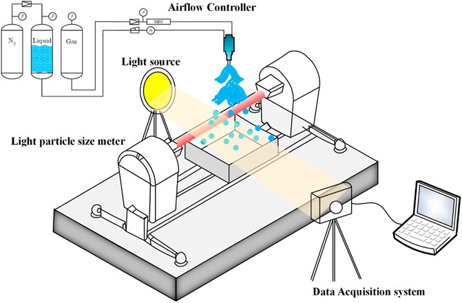
FIGURE 1. The schematic of the present experimental atomization system.
The coaxial injector schematic models are shown in Figure 2. These coaxial injectors contain a liquid and gaseous injector.
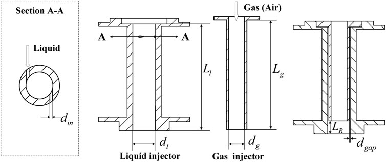
FIGURE 2. Schematic of coaxial injectors.

TABLE 1. The geometric parameters of the present gaseous injectors.
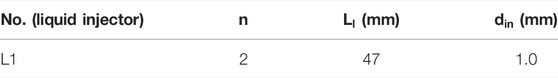
TABLE 2. The geometric parameters of the present liquid injectors.
It is shown that the gas–liquid momentum ratio is an important parameter for evaluating the coaxial injector atomization performance, which is defined as
Besides, the recessed length is another important structural parameter of the gas–liquid coaxial injectors, which would influence the atomization and self-excitation oscillation phenomena. It is defined as the ratio of the recessed length to the injector diameter, i.e.,
where
2.2 Working Condition
Different experiments have been proposed based on the gas–liquid coaxial injector cold-flow experimental platform, using water and compressed air as the working matter. In particular, the G1-1 to G3-3 gas injectors have been combined with the L1 liquid injector. The recess ratios could also be changed to investigate the impacts of these parameters on the atomization and self-oscillation performance. The detailed working conditions are shown in Table 3.
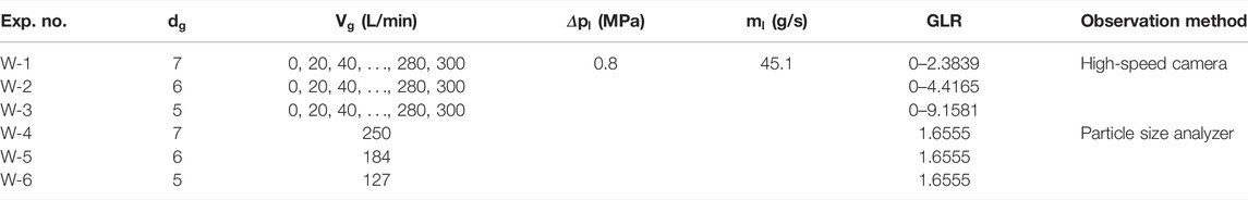
TABLE 3. Working conditions of the liquid and gas injectors to study the gas core size impacts.
It is observed that the liquid flow rates and pressure drops are fixed (45.1 g/s and 0.8 MPa) to study the impacts of different gaseous flow rates on the spray characteristics of the coaxial injectors. The gaseous flow rate varies from 0 to 300 L/min, and the corresponding gas–liquid momentum ratio varies from 0 to 9.158, correspondingly. In particular, W-1, W-2, and W-3 experiments are recorded by the high-speed camera to capture the spray morphology, breakup length, and spray angle, respectively. W-4, W-5, and W-6 experiments use the particle size analyzer to obtain the impacts of air core size on the average droplet size in the spray field.
It is indicated that various experiments have been taken to study the impacts of recess ratios on the atomization performance as well. The working conditions are shown in Table 4. The present gaseous flow rate for all injectors in Table 4’s conditions are all set as zero to eliminate the impacts of gaseous contraction impact that a liquid injector (L1) has been used. The recess ratios are from 0 to 2 and the corresponded liquid pressure drop could be varied from 0 to 1 MPa, which refers to the liquid flow rate from 0 to 48 g/s.
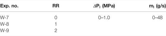
TABLE 4. Working conditions of the liquid injectors to study recess ratio impacts.
Besides, in order to study the self-oscillation characteristics of the present coaxial injectors, the following experimental conditions are given, which are shown in Table 5.
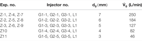
TABLE 5. Working conditions for the different self-oscillation characteristics of the coaxial injectors.
It is revealed from Table 5 that the oscillation characteristics would be measured under different gas flow rates and channel diameters. Subsequently, the injectors with no recess length are further studied to investigate the impacts of the propellant flow rate on the self-excited oscillatory properties. The oscillation characteristics of each injector are measured and analyzed as well. In particular, the experiments are performed using Z-1, Z-2, and Z-3 injector combinations with specific parameters as shown in Table 6. It should be noted that the gaseous flow rate could be changed step by step to adjust the liquid flow rate during the self-excitation oscillations under each gas flow rate.
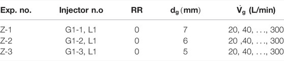
TABLE 6. The working conditions of Z-1, Z-2, and Z-3 injectors.
The atomization processes in the Z-1, Z-2, and Z-3 experiments could be captured by the high speed camera to analyze their spray features like the spray angle and breakup length. The dominant frequency of the self-oscillation phenomena could be determined by the proper orthogonal decomposition (POD) decomposition method.
3 Results and Discussion
In this section, the atomization features of the coaxial injectors like the average droplet size, breakup length, and spray angle and the effects of gaseous core size and recess length on them would be studied comprehensively. Besides, as for the self-oscillation characteristics, it includes the dominant frequency and gaseous core size. The impacts of the liquid flow rate and injector geometric parameters on the abovementioned features have been measured and analyzed in detail.
3.1 Atomization Features of Gas-Centered Coaxial Injectors
3.1.1 Impacts of the Gaseous Core Size
The spray morphology under the different gaseous core sizes are shown in Figure 3.
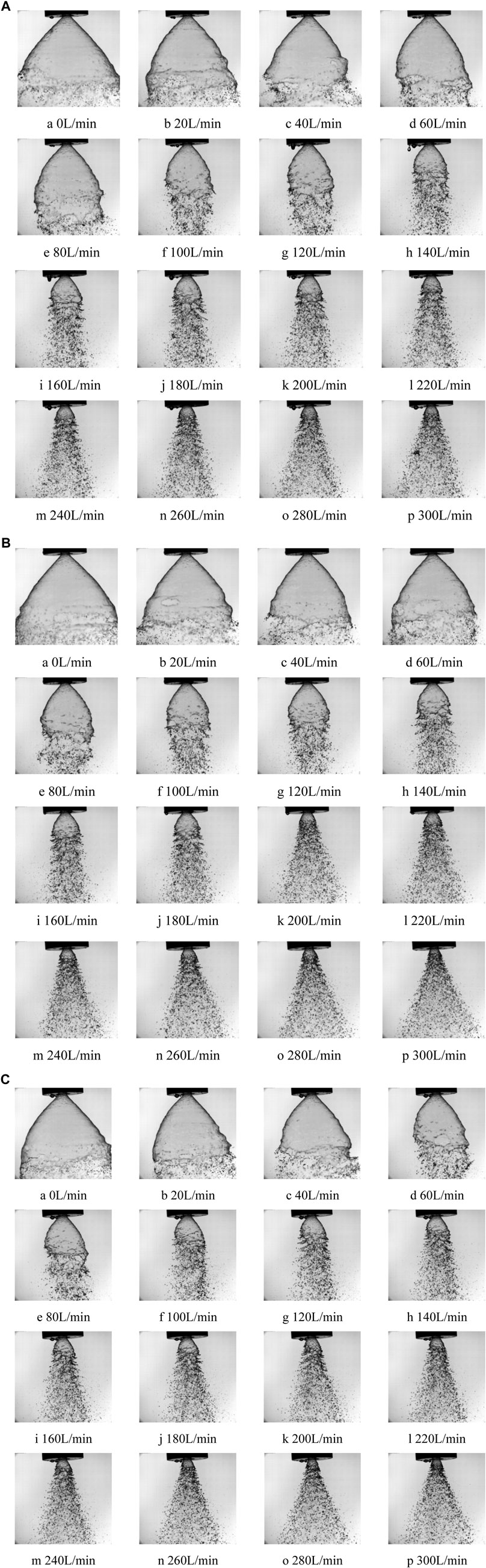
FIGURE 3. (A) Impacts of the gaseous flow rate on the atomization morphology, W-1 injector. (B) Impacts of the gaseous flow rate on the atomization morphology, W-2 injector. (C) Impacts of the gaseous flow rate on the atomization morphology, W-3 injector.
From Figure 3, it is evident that the spray morphology is quite similar for the different coaxial injectors under certain liquid flow rates. The liquid sheet shows a hollow cone shape when the gaseous flow rate is relatively low. The breakup length reduces with larger aerodynamic force. The liquid sheet then breaks up into small droplets due to the developing unstable surface waves generated by the gas–liquid shear flow.
The spray features of the different injectors have been studied quantitatively. The impacts of the gaseous flow rate on the spray cone angle are shown in Figure 4A. It is shown that the spray cone angle decreases first and then increases with larger gaseous flow rates when the liquid sheet is fully atomized. This is due to the fact that the gas flow rate from the internal gas injector is relatively fast, so the related pressure is less than the atmospheric pressure when the spray is not completely atomized. The pressure difference between the liquid sheet lets it contract inward. It is promoted with the larger gaseous flow that the spray cone angle gradually decreases. The strong air–liquid interaction completely atomizes the liquid sheet at the injector exit when the gaseous flow rate is sufficiently large, and the spray cone angle increases as well. It is revealed from the previous atomization morphology that the critical gaseous flow rate for the full atomization state is smaller with smaller gaseous core size. It could be because the gaseous flow rate is larger with smaller air core size, which leads to larger gas–liquid momentum. This ratio determines the spray pattern during the atomization processes.
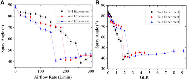
FIGURE 4. Impacts of the (A) gaseous flow rate and (B) gas-to-liquid momentum ratio on the spray cone angle for different coaxial injectors.
The impacts of the gas–liquid momentum ratio on the spray cone angle is shown in Figure 4B. It is found that the spray cone angle decreases first and then increases with a larger momentum ratio. The spray pattern changes when this ratio is about 2 and the spray is completely atomized.
The impacts of the gaseous flow rate on the breakup length have been measured as shown in Figure 5. It is illustrated that the breakup length is reduced by a larger gaseous flow rate. Since the external liquid injector structure is the same for these three experiments, the breakup length is decreased faster with smaller gas core sizes. This means that the injector with a smaller gaseous core size will have a more apparent impact on the liquid sheet breakup length, which is consistent with the measured results of the spray angle.
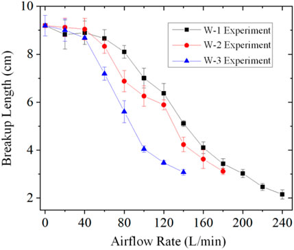
FIGURE 5. Impacts of the gaseous flow rate on the breakup length for different coaxial injectors.
Subsequently, the average droplet sizes generated by the different coaxial injectors in the spray field is measured as well. The radius distribution of the SMD for the different coaxial injectors are shown in Figure 6. The experimental measurement point is at 18 cm below the injector exit.
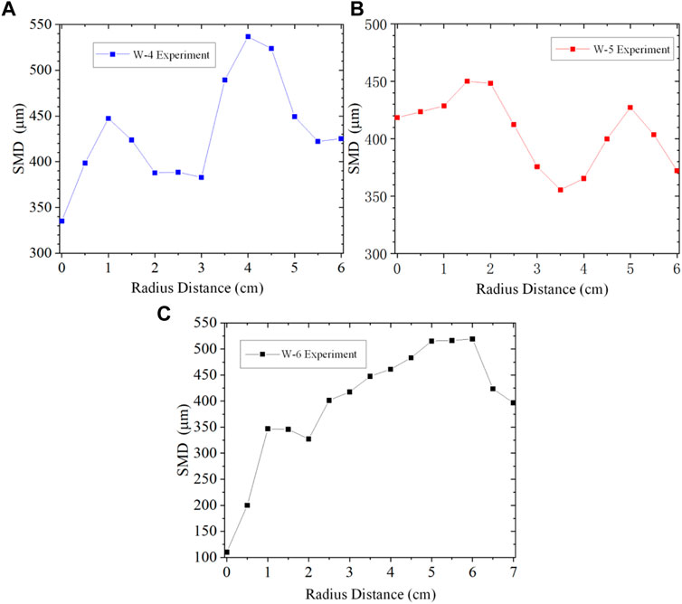
FIGURE 6. The SMD distribution along the radius distance for the different coaxial injectors: (A) W-4 experiment, (B) W-5 experiment, and (C) W-6 experiment.
As shown in Figure 6, the SMD values obtained by these three injectors vary along the radial distribution curves, and all of them show a bimodal shape. In particular, these three curves start falling when the SMD reaches the first high point when the radial distance is about 1–2 cm, then it would be raised again to the second high point at about 5 cm. Finally, the SMD is reduced by the larger radius distances. Besides, it can be seen that the bimodal tendency is suppressed by the smaller gaseous core size. It means that under a certain gaseous flow rate, the gaseous flow shows a more apparent impact on the breakup of the liquid film when the gaseous core size is smaller.
3.1.2 Impacts of the Recess Length
It is noted that the recess length also has a pronounced impact on the atomization characteristics. The geometric coefficients of the injector in experiments W-7, W-8, and W-9 are the same, and the flow rates of these three experiments are shown in Figure 7.

FIGURE 7. The flow characteristics of the three coaxial injectors.
The atomization processes of the W-7 experiment under the different pressure drops are shown in Figure 8A. It is found that the injected liquid cannot expand in total to form a liquid film when the pressure drop is lower than 0.1 MPa. It would form both small droplet and twisted ligaments. The rotating liquid column shape is hollow, twisted, and pencil shaped when the injector pressure drop further increases to 0.2 MPa. The liquid film is then divided into two parts. The upper half of the liquid film is expressed as onion shaped, while the liquid film is contracted due to the surface tension; it is then expanded again to a conical liquid film morphology. The lower part of the spray then disappears and the liquid film begins to break when the injector pressure drop reaches about 0.5 MPa. The spray is tulip shaped before a stable conical liquid film, when the pressure drop is further increased (Surya Prakash et al., 2014).
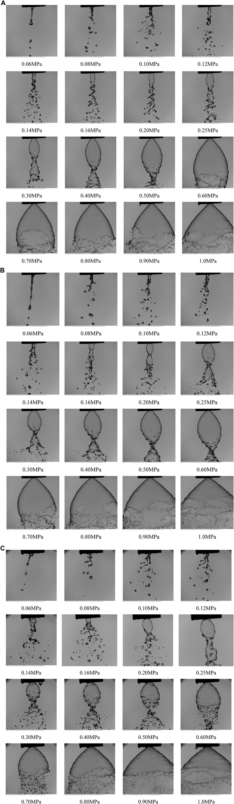
FIGURE 8. Atomization morphology generated by the (A) W-7 experiment, (B) W-8 experiment, and (C) W-9 experiment.
The subsequent atomization processes of the W-8 injector under the different pressure drops are shown in Figure 8B. It is shown that the spray in the W-8 experiment has a stronger angular momentum than the spray in the W-7 experiment due to the introduced recess length and shows a higher liquid film rotation and a larger spray cone angle under the same pressure drop.
The atomization performance of the W-9 experiment is shown in Figure 8C. The liquid film also shows a droplet-dripping, twisted-ribbon, twisted-pencil, onion-shaped, and stable-conical liquid film as the pressure drop is further increased. It reveals that the critical injector pressure drop is different for each experimental condition. The atomization features are also different for these injectors. Overall, the spray morphology in W-9 experiment is more extended and the angular momentum and spray cone angle are larger than in the W-7 and W-8 experiments.
The impacts of the recess length on the spray angle are measured and analyzed in Figure 9. It is shown that the spray angle is increased with a larger pressure drop, while the main difference is that the larger the recess length for the corresponding spray angle the larger it is for the same injector pressure drop. Therefore, different spray patterns reveal that the injector recess length has an impact on the spray characteristics of these coaxial injectors.
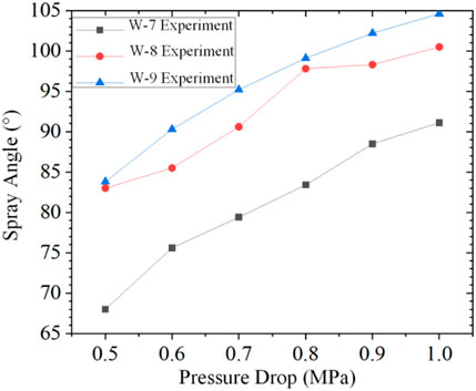
FIGURE 9. Impacts of recess length on the spray angle under different pressure drops.
The maximum width of the liquid sheet in the spray field is measured and shown in Figure 10. It is revealed that the maximum width and vertical distance is increased with a larger pressure drop. Besides, the initial maximum width increases with a longer recess length when the pressure drop is relatively low, which means that the swirl intensity is increased by the larger recess length. The balance point of the liquid sheet contraction moves downward due to the surface tension effect. The distance between the injector exit and the maximum width of the liquid sheet is shorter when the recess length is further increased.
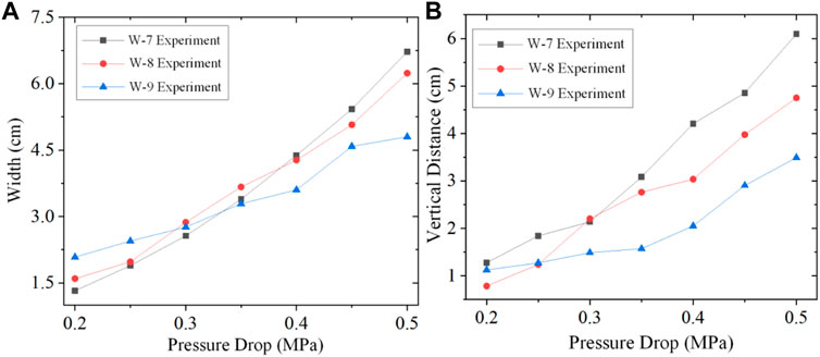
FIGURE 10. Impacts of recess length on the (A) maximum width of the liquid sheet and (B) vertical distance with the injector exit under the different pressure drops.
3.2 Self-Oscillation Features of Gas-Centered Coaxial Injectors
The self-oscillation phenomena occur for coaxial injectors under certain geometric parameters and working conditions. In the following section, the spray photographs recorded by the high speed camera and the impacts of the gaseous core size on the self-oscillation features are studied comprehensively.
3.2.1 Impacts of the Gaseous Core Size
It is noted that the self-oscillation phenomena are observed in the present experiments. The detailed processes are described as follows. First, the liquid sheet shows a conical shape when it leaves the injector exit. The stable maximum length is defined as the critical length. The liquid film breaks up into small droplets by the strong gas–liquid interaction, which happens near the central axis of the injector. The obtained spray is further expanded when the space range reaches the maximum length. The complete liquid film is thereby injected from the exit and shows a conical shape again. The abovementioned phenomena are more apparent for small liquid flow rates. The detailed processes of the different injectors are shown in Figure 11.
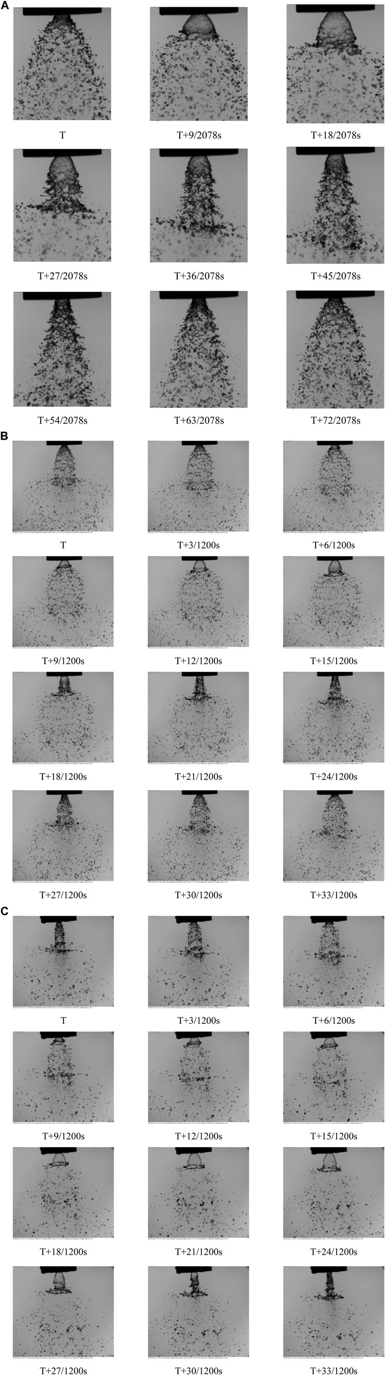
FIGURE 11. Periodic pictures of the self-oscillation injector when (A) the gaseous core size is 7 mm, the gaseous flow rate is 250 L/min, time intervals are about 9/2078 s, and the shutter time is 20
The impacts of the gaseous core size on the self-oscillation features like the critical breakup length and the oscillation frequency are analyzed. The POD is an effective way to extract information of each mode from the experimental data. It decomposes the system into several simple orthogonal modes. The modes containing a large energy are the main features of the original system, and the main features are extracted to obtain the relevant information. It should be noted that the spray density in the field is directly related to the gray value of the spray images. In particular, the gray value is increased with a larger spray density. Therefore, the oscillatory mode and its spectrum could be determined by using the POD method. According to the mode spectrum, the energy spectrum distribution (PSD) of each mode is obtained after the Fourier transform and the frequency characteristics are found from it. The obtained results are shown in Figure 12.
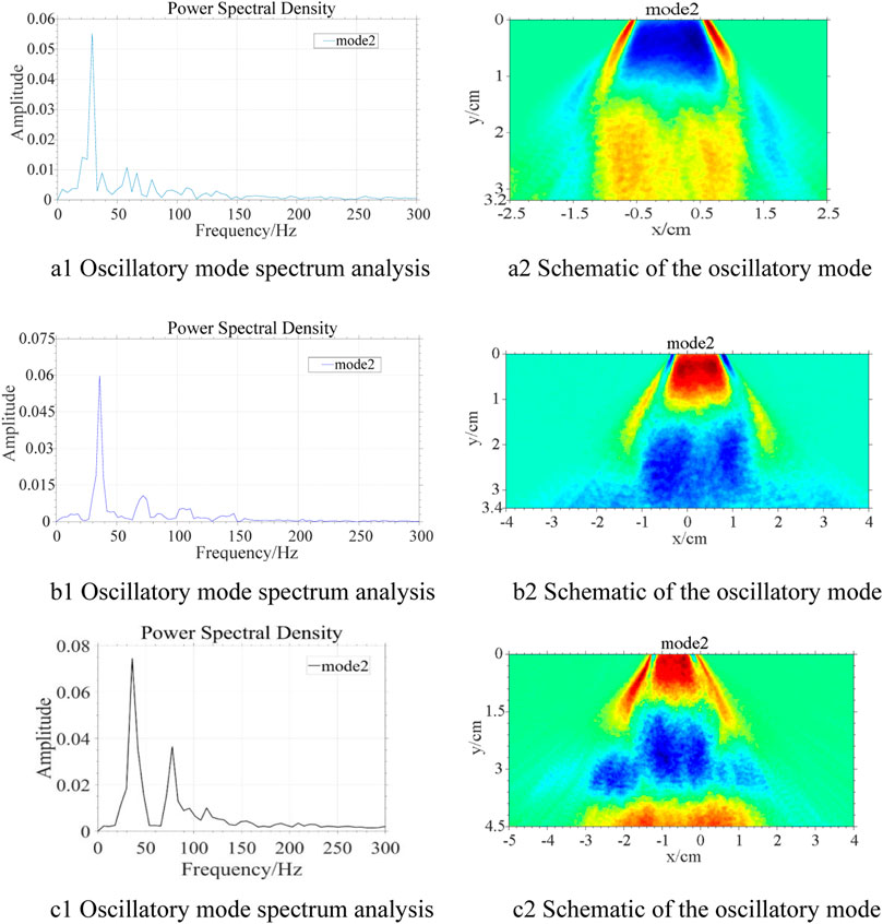
FIGURE 12. The self-oscillation characteristics (oscillatory mode spectrum and oscillatory mode) of different injectors when the air core size is (A) 7 mm, (B) 6 mm, and (C) 5 mm.
As shown in Figures 12A,B, there exist a series of low-frequency oscillations that are different from the commonly observed high-frequency oscillations in jet engines. In particular, the self-oscillation frequency is about 29 Hz when the gaseous core size is about 7 mm, and the frequency increases to 36 Hz when the gaseous core size reduces to about 6 mm. The self-oscillation intensity is amplified as its frequency is nearly the same as to when the gaseous core size further shrinks to 5 mm. Besides, as shown in Figure 12C, the spray shows more distinguished different modes, which generates various unstable surface waves along the liquid sheet surface. Therefore, the different parts of the liquid sheet lets the liquid sheet be evidently stratified when compared with the other air core size conditions.
The impacts of self-oscillation on the breakup features have been measured as well. The self-oscillation frequency is relatively low during the self-oscillation phenomena. It leads to the liquid sheet extending in a conical shape when leaving the injector exit. The maximum length at which the liquid sheet stably unfolds in the conical shape is defined as the critical breakup length. As shown in Figure 13A, the critical breakup length and spray angle increase with larger gaseous core sizes. It is revealed that the gas–liquid interaction promotes the self-oscillation intensity.
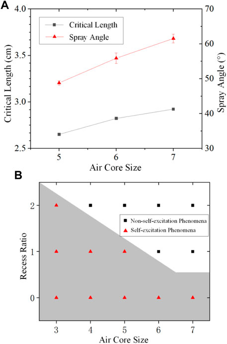
FIGURE 13. (A) The breakup features of spray under various air core sizes. (B) Parameter boundaries of self-excited oscillatory phenomena.
Besides, previous experiments have shown that the injector geometric parameters influence the self-oscillation phenomena as well. The criteria determining whether the self-oscillation phenomena would happen are shown in Figure 13B. The larger gaseous core sizes suppress the self-oscillation phenomena, while the recess length shows an opposite impact on the activation of the self-oscillation phenomena as the other parameters are kept the same.
3.2.2 Impacts of the Airflow Rate
In the following subsection, the impacts of the airflow rate and air core size on the self-oscillation phenomena are studied under different working conditions. The experimental results reveal that these phenomena are suppressed by changing the flow rate. The variations of the liquid pressure drop and flow rate for the different gaseous flow rates are measured as shown in Figure 14 when the self-oscillation phenomena are activated.
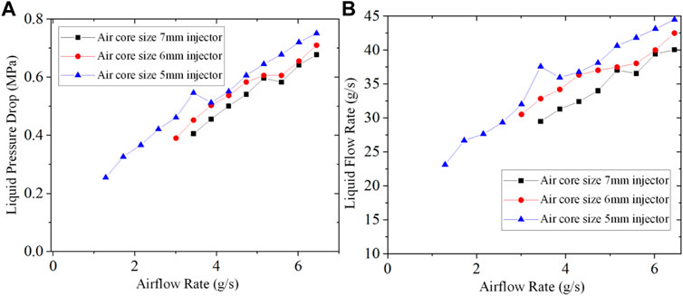
FIGURE 14. Impacts of the gaseous core size on the (A) liquid pressure drop and (B) liquid flow rate under the different gaseous flow rates.
The critical liquid flow rate increases with larger gaseous flow rates. There exist two spray patterns, i.e., a steady state spray and conical liquid film when the gas–liquid momentum ratio is relatively large. Therefore, the activation of the self-oscillation phenomena should satisfy a certain momentum ratio. Besides, the injector shows the self-oscillation phenomena when the gaseous core sizes and flow rates are relatively small. The required gaseous flow rate is larger with a larger gaseous core size for the possible self-oscillation phenomenon. Furthermore, the self-oscillation intensity is larger with a greater liquid flow rate and pressure drop.
The impacts of the gaseous core size on the parametric range for activating self-oscillation phenomena under the different gas–liquid momentum ratios are shown in Figure 15A.
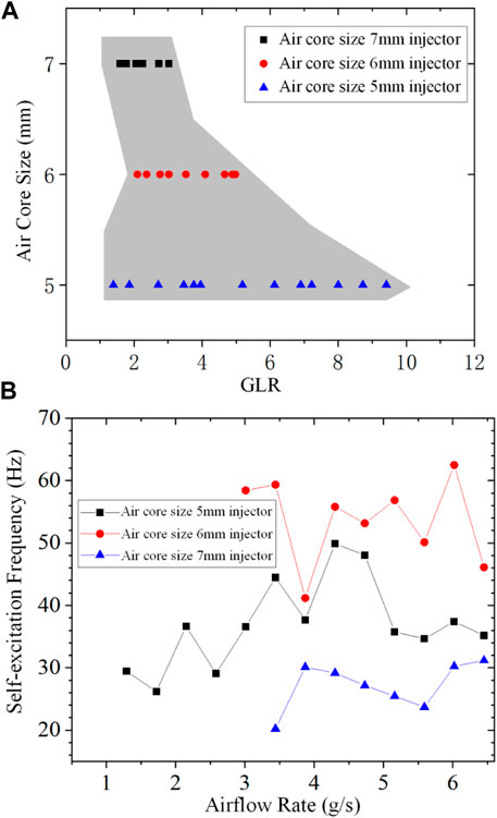
FIGURE 15. Impacts of the gaseous core size on (A) the activation of self-oscillation phenomena under the different gas–liquid momentum ratios under the different gaseous flow rates and (B) the self-oscillation frequency under the different gaseous flow rates.
The smaller gaseous core sizes widen the momentum ratio range to activate the self-oscillation phenomena. The impacts of the gaseous core sizes on the self-oscillation frequencies under the different gaseous flow rates is obtained by analyzing the spray photographs with the eigenorthogonal decomposition method.
As shown in Figure 15B, the self-oscillation frequency nearly does not change with the larger gaseous flow rates. In particular, it shows a maximum oscillation frequency when the gaseous core size is 6 mm, and the oscillation frequency is further reduced when the gaseous core sizes are about 5 and 7 mm. The physical mechanism behind the present tendency could be investigated in further research.
4 Conclusion
The present article investigates the spray and self-oscillation characteristics of a liquid sheet generated by a series of gas-centered coaxial injectors. An experimental observation system has been established to study the impacts of the gaseous core size and recess lengths on the breakup features like the breakup length, spray angle, and the corresponding self-oscillation characteristics. The main conclusions are as follows.
As for the spray characteristics of the liquid sheets generated by coaxial injectors, the gaseous flow shows a more apparent impact on the liquid sheet breakup when the gaseous core size is relatively small. This shows various SMD radius distributions with the different gaseous core sizes. Besides, the atomization morphology shows different patterns for the different injector pressure drops. There exists the drop-dripping, twisted-sheet, twisted-pencil, onion-shaped, and stable conical liquid sheet when the pressure drop is further increased and the spray angle becomes larger in addition to increases in the recess length.
As for the self-oscillation features of these coaxial injectors, the injector geometric parameters and the airflow rate impacts have been investigated. It is illustrated that there exists a relatively low-frequency oscillation for the coaxial injectors when the self-oscillation phenomena are activated. The parametric ranges between the gas–liquid momentum ratio and gaseous core size for the stable self-oscillation was obtained as well. The smaller gaseous core size and shorter recess length promoted the self-oscillation phenomena. The required liquid flow rate for activating the self-oscillation was raised by increasing the gaseous flow rate, while the self-oscillation frequency hardly varied with it.
The spray and self-oscillation characteristics of liquid sheets from the various gas-centered coaxial injectors have been obtained based on the abovementioned conclusions, which provide some useful information in making clear the detailed physical processes and improvements to the atomization quality in many industrial aspects.
Data Availability Statement
The raw data supporting the conclusion of this article will be made available by the authors, without undue reservation.
Author Contributions
LL: writing, experiment, and analyzing; YH: writing and data processing; SZ: experiment; QF: supervision and funding.
Funding
This research is supported by the National Natural Science Foundation of China (Grant Nos. 11872091, 11922201, and U1837211).
Conflict of Interest
The authors declare that the research was conducted in the absence of any commercial or financial relationships that could be construed as a potential conflict of interest.
Publisher’s Note
All claims expressed in this article are solely those of the authors and do not necessarily represent those of their affiliated organizations, or those of the publisher, the editors, and the reviewers. Any product that may be evaluated in this article, or claim that may be made by its manufacturer, is not guaranteed or endorsed by the publisher.
References
Anand, R., Ajayalal, P., Kumar, V., Salih, A., and Nandakumar, K. (2017). Spray and Atomization Characteristics of Gas-Centered Swirl Coaxial Injectors. Int. J. Spray Combustion Dyn. 9 (2), 127–140. doi:10.1177/1756827716660225
Bai, X., Cao, P., Li, Q., and Cheng, P. (2021). The Break Phenomenon of Self-Pulsation for Liquid-Centered Swirl Coaxial Injectors. Int. J. Multiphase Flow 142, 103708. doi:10.1016/j.ijmultiphaseflow.2021.103708
Bazarov, V. (1996). “Influence of Propellant Injector Stationary and Dynamic Parameters on High Frequency Combustion Stability,” in Proceeding of the 32nd AIAA/ASME/SAE/ASEE Joint Propulsion Conference and Exhibit, Lake Buena Vista,FL,U.S.A, July 1996 (American Institute of Aeronautics and Astronautics), 3119. doi:10.2514/6.1996-3119
Bazarov, V. (1998). “Non-linear Interactions in Liquid-Propellant Rocket Engine Injectors,” in Proceeding of the 34th AIAA/ASME/SAE/ASEE Joint Propulsion Conference and Exhibit, Cleveland,OH,U.S.A., July 1998 (American Institute of Aeronautics and Astronautics), 4039. doi:10.2514/6.1998-4039
Bazarov, V. G., and Yang, V. (1998). Liquid-Propellant Rocket Engine Injector Dynamics. J. Propulsion Power 14 (5), 797–806. doi:10.2514/2.5343
Chen, C., He, X., Liu, C., Yang, Y., and Tang, Z. (2021). Experimental Study on the Flow Field Distribution Characteristics of a Gas-Liquid Swirl Coaxial Injector under Ambient Pressure. Aerospace Sci. Tech. 114, 106757. doi:10.1016/j.ast.2021.106757
Ding, J.-W., Li, G.-X., and Yu, Y.-S. (2017). The Instability and Droplet Size Distribution of Liquid-Liquid Coaxial Swirling spray: An Experimental Investigation. Exp. Therm. Fluid Sci. 82, 166–173. doi:10.1016/j.expthermflusci.2016.11.014
Eberhart, C., Lineberry, D., and Frederick, R. (2012). “Propellant Throttling Effects on Self-Pulsation of Liquid Rocket Swirl-Coaxial Injection,” in Proceeding of the 48th AIAA/ASME/SAE/ASEE Joint Propulsion Conference & Exhibit, Atlanta, Georgia, July 2012 (American Institute of Aeronautics and Astronautics), 4204. doi:10.2514/6.2012-4204
Gautam, V., and Gupta, A. K. (2009). Cryogenic Flow and Atomization from a Coaxial Injector. J. Propulsion Power 25 (1), 33–39. doi:10.2514/1.28921
Im, J. H., Kim, D., Yoon, Y., Roh, T., and Koo, J. (2005). “Self-pulsation Characteristics of a Swirl Coaxial Injector with Various Injection and Geometric Conditions,” in Proceeding of the 41st AIAA/ASME/SAE/ASEE Joint Propulsion Conference & Exhibit, Tucson, Arizona, July 2005 (American Institute of Aeronautics and Astronautics), 3749. doi:10.2514/6.2005-3749
Im, J. H., and Yoon, Y. (2008). “The Effects of the Ambient Pressure on Self-Pulsation Characteristics of a Gas/liquid Swirl Coaxial Injector,” in Proceeding of the 44th AIAA/ASME/SAE/ASEE Joint Propulsion Conference & Exhibit, Hartford,CT, July 2008 (American Institute of Aeronautics and Astronautics), 4850. doi:10.2514/6.2008-4850
Jeon, J., Hong, M., Han, Y. M., and Lee, S. Y. (2011). Experimental Study on spray Characteristics of Gas-Centered Swirl Coaxial Injectors. J. Fluids Eng. 133 (12), 121303. doi:10.1115/1.4005344
Kang, Z., Li, Q., Cheng, P., Zhang, X., and Wang, Z.-g. (2016). Effects of Self-Pulsation on the spray Characteristics of Gas-Liquid Swirl Coaxial Injector. Acta Astronautica 127, 249–259. doi:10.1016/j.actaastro.2016.05.038
Kulkarni, V., Sivakumar, D., Oommen, C., and Tharakan, T. J. (2010). Liquid Sheet Breakup in Gas-Centered Swirl Coaxial Atomizers. J. Fluids Eng. 132 (1), 011303. doi:10.1115/1.4000737
Li, T., Nishida, K., and Hiroyasu, H. (2011). Droplet Size Distribution and Evaporation Characteristics of Fuel spray by a Swirl Type Atomizer. Fuel 90 (7), 2367–2376. doi:10.1016/j.fuel.2011.03.011
Liu, H.-F., Li, W.-F., Gong, X., Cao, X.-K., Xu, J.-L., Chen, X.-L., et al. (2006). Effect of Liquid Jet Diameter on Performance of Coaxial Two-Fluid Airblast Atomizers. Chem. Eng. Process. Process Intensification 45 (4), 240–245. doi:10.1016/j.cep.2005.08.003
Liu, J., Zhang, X.-Q., Li, Q.-L., and Wang, Z.-G. (2013). Effect of Geometric Parameters on the spray Cone Angle in the Pressure Swirl Injector. Proc. Inst. Mech. Eng. G: J. Aerospace Eng. 227 (2), 342–353. doi:10.1177/0954410011432233
Liu, L., Yang, L., Fu, Q., and Cui, X. (2018). Improved Modeling of Free Power-Law Liquid Sheets by Weighted-Residual Approximations. Int. J. Multiphase Flow 107, 146–155. doi:10.1016/j.ijmultiphaseflow.2018.05.022
Liu, L. H., Yang, L. J., and Fu, Q. F. (2020). Droplet Size Spatial Distribution Model of Liquid Jets Injected into Subsonic Crossflow. Int. J. Aerospace Eng. 12 (1), 931729. doi:10.1155/2020/9317295
Liu, L., Fu, Q., and Yang, L. (2021). Linear Stability Analysis of Liquid Jet Exposed to Subsonic Crossflow with Heat and Mass Transfer. Phys. Fluids 33 (3), 034111. doi:10.1063/5.0040538
Surya Prakash, R., Gadgil, H., and Raghunandan, B. N. (2014). Breakup Processes of Pressure Swirl spray in Gaseous Cross-Flow. Int. J. Multiphase Flow 66 (7), 79–91. doi:10.1016/j.ijmultiphaseflow.2014.07.002
Xue, J., Jog, M. A., Jeng, S. M., Steinthorsson, E., and Benjamin, M. A. (2004). Effect of Geometric Parameters on Simplex Atomizer Performance. AIAA J. 42 (12), 2408–2415. doi:10.2514/1.2983
Keywords: coaxial injector, self-oscillation, recess length, spray angle, SMD (Sauter mean diameter)
Citation: Liu L-H, Han Y-F, Zhang S-Q and Fu Q-F (2022) Experimental Study on the Spray and Self-Excitation Oscillation Characteristics of Gas-Centered Coaxial Injectors. Front. Energy Res. 10:865431. doi: 10.3389/fenrg.2022.865431
Received: 29 January 2022; Accepted: 11 April 2022;
Published: 10 May 2022.
Edited by:
Xiao Liu, Harbin Engineering University, ChinaReviewed by:
Zongjie Hu, Tongji University, ChinaQing-Lian Li, National University of Defense Technology, China
Copyright © 2022 Liu, Han, Zhang and Fu. This is an open-access article distributed under the terms of the Creative Commons Attribution License (CC BY). The use, distribution or reproduction in other forums is permitted, provided the original author(s) and the copyright owner(s) are credited and that the original publication in this journal is cited, in accordance with accepted academic practice. No use, distribution or reproduction is permitted which does not comply with these terms.
*Correspondence: Qing-Fei Fu, ZnVxaW5nZmVpQGJ1YWEuZWR1LmNu