 Mohammad Amir
 Anjani Kumar Prajapati
 Shady S. Refaat
- 1Department of Electrical Engineering, Faculty of Engineering and Technology, Jamia Millia Islamia Central University, Delhi, India
- 2Department of Electrical Engineering, MMM University of Technology, Gorakhpur, India
- 3Department of Electrical Engineering, Texas A&M University, Doha, Qatar
- 4School of Physics, Engineering and Computer Science, Department of Engineering, University of Hertfordshire, Hatfield, United Kingdom
Today’s stochastic grid system is experiencing huge voltage fluctuations, which is responsible for power quality issues in the smart microgrid network due to its intermittent nature as well as penetration of hybrid renewable resources. Thus, the dynamic performance evaluation and their control are essential to sustaining the stability of the grid network. A d-q controller mechanism is suggested to maintain the balance of the distributed generation network and grid side network. A dynamic control mechanism of voltage source converter (VSC) is presented in the MPPT-based wind power generating station, where an induction generator generates the power by the optimal control of the wind energy-based subsystem. The distributed hybrid generation (solar PV and wind) subsystem’s output terminal is linked to the DC bus bar’s common link via the VSC. A VSI is utilized to convert the desired DC power to alternating current power. To regulate and improve the performance of the proposed hybrid power generating systems (HPGS), a supercapacitor (SC) is used to smooth out the ripple on the distribution side in the power grid. Furthermore, the dynamic stability of grid-connected solar PV and wind power generation systems is investigated. This article also proposed an effective control scheme for the SC in HPGS under the influence of weak grid conditions. This article aimed to validate the efficiency of the VSI topology; a PI controller stability enhancement approach is used in a proposed grid system under various disturbance conditions. Finally, the simulation results and FFT-based power quality response analysis are validated through the effective utilization of an SC.
1 Introduction
Recently, the use of grid-connected hybrid renewable energy resources (like solar, wind, and hydro) increases rapidly because of the huge expansion in the load demand on the distributed generating system (Kim et al., 2008). But on the other hand, it prompts significant issues and consequences by the intermittent nature of these hybrid energy resources (Salimi et al., 2021; Sun et al., 2021). Despite the availability of energy resources, grid modernization and consumers interest are increasing in the energy market (Amir and Khan, 2021). To meet the desired electricity demand, the most effective solution is to use affordable sustainable energy sources (Armghan et al., 2020; Sanguesa et al., 2021; ). According to the energy reports (MNRE, 2019), in India, 56 percent of wind energy and 34 per cent of solar power supplies fulfill the consumer’s electricity demand. That was generated by a key factor in promoting sustainable energy sources such as PV and wind-based resources and their interconnection with the on/off the grid (ToghaniHolari et al., 2020). The solar and wind energy hybrid power generation systems (HPGS) were primarily extended because the solar power plant’s common accessibility and output generating power are dependent on the following environmental factors: individual irradiance accessibility, ambient temperature, and wind velocity (Okundamiya, 2021). These resources produce a discontinuous and irregular voltage as a consequence of the substantial impact of hybrid RES by the climate and weather variation (Ni et al., 2021; Praveen Kumar et al., 2021). To help with these issues, the hybrid renewable energy network is integrated with the grid network to identify resource reliability. Furthermore, the MPPT control technique is required to maximize the generation and control the most unusual power sources (BhatNempu and Jayalakshmi, 2020). Various generation control methods have comprised MPPT control ((perturbation and observation (P and O), hill-climbing, etc.), intelligent-based genetic hybrid system, fuzzy-based control, artificial neural network (Amir and Zaheeruddin, 2019), and other machine learning approaches to maximize the distributed power from variable renewable resources (Chandrasekaran et al., 2021). On the other hand, various research studies proposed the optimal controller design and their optimization approach for the grid-connected photovoltaic (PV) power generation system. Although the control approach was presented and mainly focused on the hybrid development of the wind-photovoltaic-based stand-alone system (Soliman et al., 2018), there is a huge challenge in the practical control design for large stand-alone photovoltaic and wind-based hybrid power generation systems. The dynamic stability of a grid-connected distributed generation station is coupled with different stages of the power transformer (Urooj et al., 2021) and converter mechanism, which is having a simultaneous diesel dynamo, and dynamic energy storage to utilize the maximum generation curve for the development of remote emergency backup systems.
The basic control structure of a grid-connected hybrid resource topology in a smart grid is shown in Figure 1. To improve the effectiveness of battery systems with HPGS, various research studies were performed (Amir and Srivastava, 2018; Shayeghi et al., 2020). A self-control approach of charge control was built with BSS at different levels. The utilization of reactive power (Q) limiters to increase the dynamic stability of the grid-connected wind–photovoltaic HPGS throughout the DC-link has been demonstrated in the study by Krishan and Suhag (2020).To stabilize the power, super capacitors (SC) were deployed in a hybrid microgrid system (Ponnuru et al., 2021). It should be taken into consideration that nearly all the suggested control HPGS approaches had been mostly dependent on wind and PV subsystems. This is caused by the availability and potential of hybrid wind and PV to supplement other resources. However, in recent years, wind energy is usually an enormous renewable energy resource that has recently been (Sharma and Suhag, 2018) regularly evolving in the direction of commercialized distributed generation in smart microgrids (Kumar et al., 2021). It is stated that the utilization of ocean energy may come up with an important role in the emerging remote power generation technology in the coming years (Patel et al., 2020). Typically, among all types of the available power station like wind plants and ocean energy, the wind power station is usually having the key thing of many gripping as well as favorable options for power generation credited into its attributes regarding excessive potential stability in smart grid operation (Sanki et al., 2021). However, various control analyses of WPGS methods have been performed and demonstrated in the study by Punna et al. (2021). The research presented in the study by Argyrou et al. (2021) is a feasibility analysis of dynamic control of the photovoltaic–wind hybrid sustainable energy system in islands in Malaysia. In most cases (Wang and Lin, 2007), the investigation and implementation of SC for optimal performance evaluation are examined through the root-loci results and analysis under the inherent value of resources to control generating output. A schematic framework of an HPGS grid-connected system with SC is demonstrated in Figure 1.
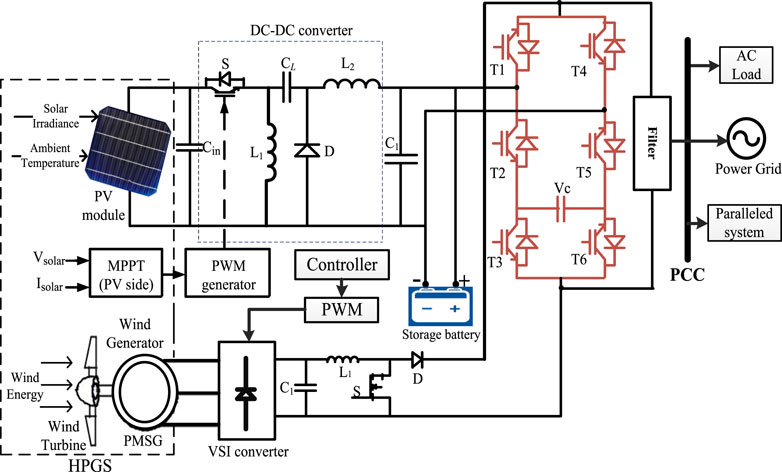
FIGURE 1. Schematic block illustration of the grid-connected HPGS through inverter’s topology.
Earlier, Al-Dhalaan et al. (1998) research work aimed the utilization of self-commutation-based inverters. The controlling parameters such as V/F are necessary for islanding detection. Some control techniques regarding islanding detection and their control are presented (Pinto and Panda, 2016). However, Ravikumar and Venkatanarayanan (2020) showed a framework of converter control and employed for grid-connected solar PV systems. This research investigates a power regulatory control in hybrid (solar and wind) distributed power systems based on the MPPT control. To ensure the effective utilization of hybrid resources, the Fuzzy-based FIS method is employed to achieve the MPPT for the hybrid (solar PV module and WT) subsystem. In this article, we will examine the transient stability and Q compensation control in the HPGS using a supercapacitor. It provides efficient utilization of energy resources and decreases consumption of battery storage, thus enhancing battery health (Faessler, 2021). The proposed system is investigated with the MATLAB Simulink tool.
This article offers the dynamic stability enhancement strategy and the performance steady-state characteristics of the HPGS, which is delivering power to the demand-side loads, for the improvement in the HPGS variables under grid (Amir and Srivastava, 2019). Also, a voltage stabilization scheme is presented for the supercapacitor (SC) in the HPGS under the influence of weak grid conditions. HES, based on the PV system connected to the weak grid, was considered for the evaluation of the system. The novel control scheme was designed to enhance quality power issues, also caused the reduction of ripples in the content through the VSI system with the DC link, and also improved the stability range of the HPGS by retaining the performance of the SC. Also, the proposed HES was designed and simulated in the MATLAB-R2021b tool, and the enhancement in the SC and PI controller scheme over variation in different parameters like improvisation using d-q control in DC link voltage was verified. Respectively, a significant drop in the ripple contents was present in VSI normal operation, and finally, the better dynamic performance of HPGS was integrated to the weak grid.
The remaining part of the article proceeds as follows: In Section 2, the design and mathematical modeling are presented. The control mechanism of the HPGS and converter topology is discussed in Section 3. The results of the suggested SC and controller topology for the proposed HPGS model are presented in Section 4. At last, the key conclusions and future framework of the HPGS are shown in the last section.
2 Design of the Grid-Connected HPGS Model
The wind energy subsystem and PV subsystems are coupled to the grid of the distributed network, as referred from Figure 1. The step-up converter connected to the PV module consists of an MPPT tracking algorithm. Although the power delivered to the grid via a hybrid system is fluctuating in nature, a supercapacitor (SC) is used to minimize the ripples and harmonics (Dai et al., 2016). The material used for constructing the supercapacitor has the characteristics of higher quick repose time, high power density, and does not require any cooling system (Urooj et al., 2020; Adil et al., 2022). The supercapacitor also maintained a balanced active power operation of the converter topology so that the interconnected converter and inverter can perform smoothly. The control mechanism for the VSI topology is presented in equations ((Eqs 1, 3, 5) for “d” parameter and (Eqs 2, 4, 6) for “q” parameter). The VSI control is shown in Figure 1, in which computation and control of grid power through LC filter (Naidu et al., 2019), a DC link network line, and a multilevel converter topology.
The dynamic control units of all these subsystems can be expressed from Eqs 1–6, where (
2.1 Design of a Solar PV Subsystem With a Converter Circuit
Generally, the PV module shows a non-linear power characteristic, which varies as solar irradiation (in kW/m2) and ambient temperature vary. The model’s classes of grid systems with PV cells have been described in several pieces of the literature (Estévez-Bén et al., 2020). As a distributed intermittent power resource, a solar PV module is reflected as the significant importance in the HPGS. The operational framework of a solar PV cell formulates the key characteristic in building a solar PV module by Eq. 7 (Patel, 2006). The photovoltaic module is made up of various PV cells interconnected in sequences of the array. The PV module is developed by a series of PV cells that are associated in a particular order. The schematic circuit of the stand-alone PV cell with the diode is shown in Figure 2A.
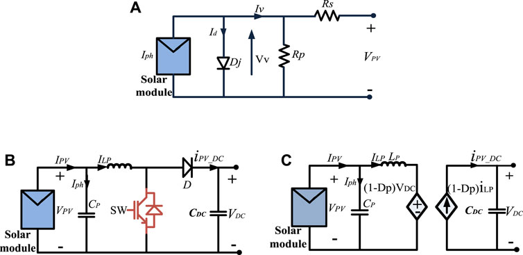
FIGURE 2. (A) Circuit of stand-alone single photovoltaic cell, (B) dynamic PV, converter circuit diagram, and (C) equivalent diagram.
This circuit consists of a PV cell that is composed of the power supply current
Here,
Additionally, generated current (
where T is the cell temperature (in oK) and G is the inversion (in K) and photovoltaic irradiance (in kW/m2). Individually, for instance, the electron energy is related within semiconductors (
Here Fc is typically the filter capacitance,
The power and current characteristics with respect to the voltage of a PV module are demonstrated in Figure 3. The proposed solar PV module is simulated for average insolation (800 W/m2) with a temperature of 27
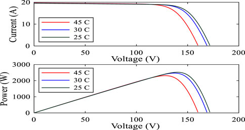
FIGURE 3. I-V and P-V characteristics of 4 series modules and 2 parallel strings at 25
2.2 Mathematical Modeling of Solar PV Inverters
The main objective is to feed extracted HPGS power via the boost conversion stage into the distributed grid by distributed grid-side converters. This is accomplished by the control of DC-link voltage as mentioned in the study by Hoon et al. (2016). In this research work, a VSI was linked to the distributed grid through an L-type filter for better response. Similarly, boost converters or the PV inverters have been controlled by the controlling of the duty cycles, and hence, output voltage was regulated. Various techniques based on PWM can be employed to generate the duty cycle for the inverters. A bipolar modulation has been preferred due to its low leakage current. This is important for transformer-less PV systems. There are two switching states in bipolar modulation: 1). SW1, SW4 are on, and SW2, SW3 are off, and 2). SW1, SW4 are off, and SW2, SW3 is on. Required expressions are given by Eq. 8.
where
High-order filters have been used for the suppression of desired harmonics; it is a combination of L and C together. Therefore, higher frequency harmonics have been suppressed by the LCL filter. A damping-based resistor is generally employed in the design of an L-C-L filter to rectify the system resonance issues that may be responsible for instability in a hybrid grid system (Teodorescu, 2011).
The FFT-based THD analysis of voltage characteristics is shown in Figure 4. Initially, when the load is not increasing, the THD in the distributed voltage is found at 14.67% and the waveform has a nominal value of RMS voltage.
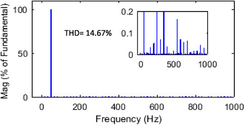
FIGURE 4. FFT window for RL load voltage.
2.3 WPGS for VSC Designed
The design of the wind power generation control system is based on a mass-spring-damper control system (Kumar et al., 2021) that can be modeled as
where the gear operator is symbolized by p, the floater wind speed is denoted by
In Eq. 19,
The control mechanism of WPGS for VSC is designed based on d and q axis parameters related to the particular translation for the LPMG, which is modified in the control operator associated with the VSC. The operation of the WPGS control operator is to get optimum energy coming from the wind energy resources and enhance the energy in the LPMG. In research (Kulkarni et al., 2016), we can evaluate the energy loss in the particular LPMG and the effective energy transformed from the wind resources to manage and simply by d and q axis parameters of the LPMG (
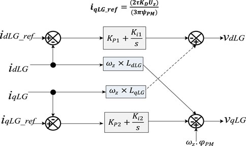
FIGURE 5. Representation of controller framework used for the design of WPGS.
2.4 Implementation of DC-DC/DC-AC Topologies
Solar and wind are both energy resources that are intermittent in nature. Thus, stability can be improved by the hybrid resources of these two systems to comply with the remote areas. These systems can be further employed for the application of storage systems through the admittable converter systems, that is, AC-DC converters, then DC-DC converters, and again DC-AC converters. The load demands can be consummated by these renewable sources combined with storage systems and various converter/inverter systems. This hybrid system has shown diverse dominance to supply the energy demand by converter topology. Eqs 21, 22 used for the DC-to-DC converter for boost operation are expressed as follows:
Eqs 21, 22 are representing the converter state vector model and its output,
The output voltage on a per-unit basis across the VSI terminals is given as follows, in Eq. 23:
In Eq. 23,
where [X] is representing the state vector, [U] is the control input vector, and
Here,
where
2.4.1 Mathematical Modeling of a DC-DC Boost Converter
DC-to-DC converters bring forth the loads and PV modules. DC-to-DC boost converters have inherent properties like higher power density and faster response during transient periods. The primary components of the DC-to-DC converters are inductance (L), a diode (D), filter capacitance (C), and a high-power semiconductor (MOSFET/IGBT) switch. Usually, they are used in PV inverter systems to find their application for the control of power extraction in PV systems with the appropriate implementation of MPPT algorithms (Elbarbary and Alranini, 2021). The purpose of MPPT in the PV-based subsystem is to continuously extract maximum power from solar PV modules irrespective of the load condition or weather. In general, an efficient MPPT algorithm can be defined based on three main aspects: fast dynamic response, high accuracy under the steady-state condition, and robustness to disturbances. Considering these aspects, the Perturb and Observe (P&O) algorithm is widely employed for maximum power (Kollimalla and Mishra, 2013). To vary the duty cycle (
where
Here,
2.5 Supercapacitor and DC-DC Converter
The equivalent circuit of the supercapacitor (SC) is shown in Figure 6A. In addition to the capacitance (CSC) of the SC, the optimal placement of SC represents as well as holds into consideration reactive power compensation using SC. From Figure 6A, the dynamic computation of the SC is employed and represented by Eq. 31.
where SC is the voltage (
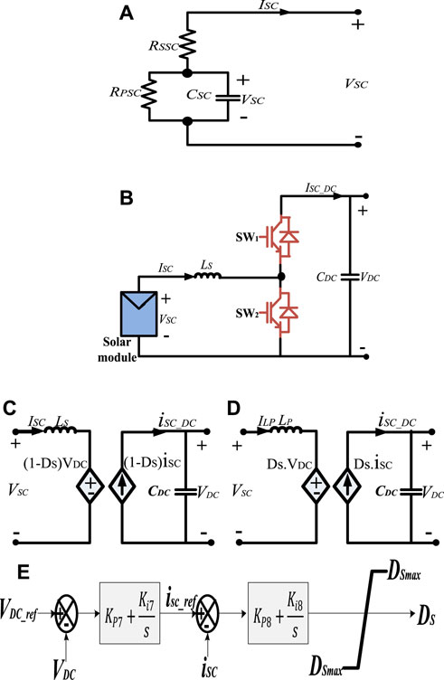
FIGURE 6. (A) Equivalent circuit of an SC, (B) DC-DC converter comprises two switches (SW1 and SW2), (C) simplified structure, (D) Framework of a back-to-back DC-DC converter. (E) Control structural layout of the DC/DC converter topology for SC.
The simplified layout of the control schemes is presented in Figure 6B. The DC-DC converter comprises two switches (SW1 and SW2), which are operated in a switch operation. The converter is enabled by the boost setting of the circulation current. Switch SW2 works as a switch, whereas SW1 works as a diode, and the energy is fed by the SC to the DC link. Furthermore, once operating the DC-DC converter in the supercharged condition, the transitioning approach is usually overlooked. Figures 6C,D describe the active mean value of bidirectional DC-DC topology, which is step-down and setting of desired voltage. The mathematical expression of the converter mode topology is given in the following text.
a) In the boost mode:
b) In the buck mode:
where
The control configuration of a typical bilateral DC-to-DC converter via DC link and the SC is capable of maintaining the active power flow, as presented in Figure 6E. Generally, a bidirectional DC-to-DC converter-based controller is employed, which is dependent on current control loops. The external current control loop measures the
3 Control Mechanism and Performance Evaluation by the Proposed Controller
This section depicts the proposed control approach for the HPGS. The main goal of controlling the HPGS is to decrease harmonics and ripples in the grid, ensuring that the network’s stability is maintained. The solar PV modules and wind power generating system reached to the distributed load via the DC-to-DC step-up-based converter and a controlled VSC. Although the bidirectional DC-to-DC converter maintains the DC side voltage, the controlled VSI is responsible for supply grid power management. The detailed study of the control mechanism is discussed for different aspects.
3.1 Control Mechanism of Step-Up Converter Integrated With the Solar PV Subsystem
The power generated by the solar PV module is fluctuating and changes with the solar irradiance and temperature. To operate the HPGS efficiently, the maximum power delivered by the PV module needs to monitor constantly. To achieve this objective, the step-up DC/DC converter associated with the PV module is regulated to control the
3.2 Control Mechanism of WPGS for VSC Designed
The controller layout of voltage d-q axis parameters is represented in Figure 7A. The controller is associated with the VSI, which is utilized to manage the distributed energy transmitted via the VSI, and also to stabilize the voltage value of the PCC at the grid side. To get the optimal control associated with the active grid elements, the active power of the VSI is carried out within the d-q axis lined up at the PCC. As a result, the energy transmitted using the voltage source inverter associated with the PCC is managed by the
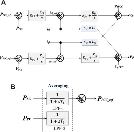
FIGURE 7. (A) VSI external control mechanism and (B) block diagram with LPF-1 and LPF-2 for
The active power is controlled through the VSI via reference PCC of the HPGS (PV and wind power generating systems). Thus, the control mechanism allows the VSI to smoothly transmit the HPGS-based electricity to the grid. It can be achieved by applying the external control scheme as presented in Figure 7B. The developed HPGS power is transferred through the low-pass filter (LPF).
The time constant of low-pass filters is symbolized by T1 and T2, respectively, as shown in Figure 7B. To minimize the power variation caused by wind, speed fluctuation (T1) should be chosen equivalent to the wind duration (Tw). However, another constant can be chosen, that is, T1 to control the power developed by PLG and the PV module.
3.3 Control Through P&O-Based MPPT Controller
The voltage controller associated with a grid-connected inverter has been designed in three parts: voltage regulator for
It is observed from Figure 8 that
where magnitude
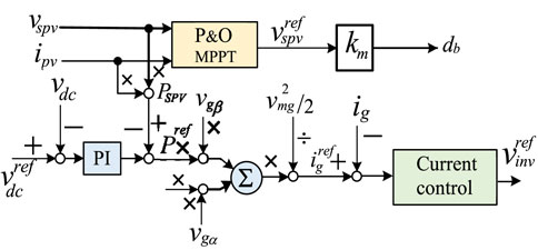
FIGURE 8. Inverter control block with PI and current controller.
In Eq. 38, PR-based controller is signified by
3.4 DC Link Voltage Balancing Controller
In a grid-connected VSI, two control loops (external and internal) are typically employed (Hossain et al., 2017). The external control loop is employed to power control and control power fed into the distribution power grid through the DC link. However, the inner control loop is employed for current control and manages the power quality problems in faster response (Hossain et al., 2017). There are different types of proportional control schemes for the outer control power loop which depends on grid operation. But the most common control scheme is PI through the DC link voltage controller presented in Figure 9.
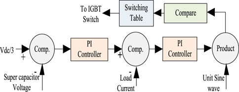
FIGURE 9. DC link voltage balancing by PI-based controller.
For the control of DC-link voltage, a closed-loop controller is needed to adjust within a specified voltage limit. The reference parameters of DC link voltages are adjusted by a voltage controller-based external loop, which controls the injected distributed grid current values. DC voltage was fed through a proposed PV module to regulate a reference current (iref) for injected grid current (igrid). The DC voltage control is usually controlled using a PI-based controller. A PI controller is employed for DC link voltage balance. This PI controller representation is shown in Figure 9.
3.4.1 Converter Performance Evaluation Under Proposed PI Control Scheme
To decrease the error and enhance the dynamic stability of VSI (Dong et al., 2019), the operational capacity of the PI controller utilizes P control flow in VSI.
Figure 10A displays the duty ratio (in %) with respect to output voltage for the testing of VSI. From this response, it is observed that because the load variation scenario at t = 0.2 s characteristic is fluctuating, it further achieves a new stable state after t = 0.35 s.
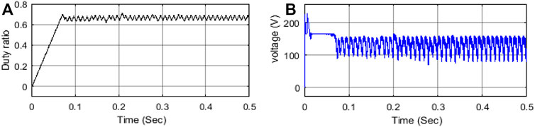
FIGURE 10. (A) Duty ratio and (B) VSI output.
3.5 Operational Control of SC for Stability Enhancement Under Weak Grid Condition
In Figure 11, the inverter configuration has been shown, which is connected through an inductor–capacitor–inductor (LCL) filter scheme. Here DC side of the inverter is interconnected with a supercapacitor (SC). A buck-boost (DC-to-DC) converter has taken advantage of connecting SC, which employs an inductor
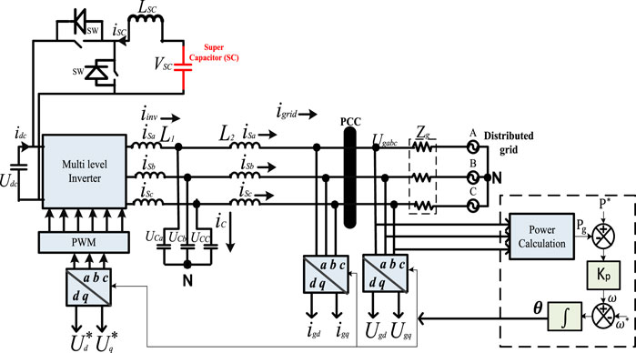
FIGURE 11. Optimal placement of the SC connected HPGS under weak grid.
3.5.1 Control Scheme for the HPGS Integrated to a Weak Grid
Figure 12 exhibits the control structure for the control of DC link voltage and reactive power connected to the LCL filter, where
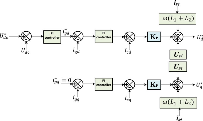
FIGURE 12. Voltage control scheme through PI controller for the grid-connected VSI.
where
The control scheme discussed previously is not appropriate for the poor grid connection. The following reasons are listed below in three steps.
a) Change in input current/power directly reflected into the reference currents is given in Eqs 41, 42.
where
b) The voltage control loop has a smaller bandwidth than the grid current control. So, in a poor grid-connected system where grid impedance is considered, the feed-forward-decoupled control scheme for
But the main issue is here that
In Eqs 47, 48,
c) Due to the presence of the terms
In Eqs 51, 52,
Due to the presence of the terms
4 Results Analysis and Discussion
4.1 Validation Through Variation in Solar PV Power
The specific range of solar irradiance of the solar PV module is shown in Figure 13A. The variation in irradiance was taken for 0.5 s in the MATLAB simulation tool. The fluctuation of the solar power irradiance is supposed to consist of substantial imbalances due to the intermittent nature of the local atmospheric circumstances.
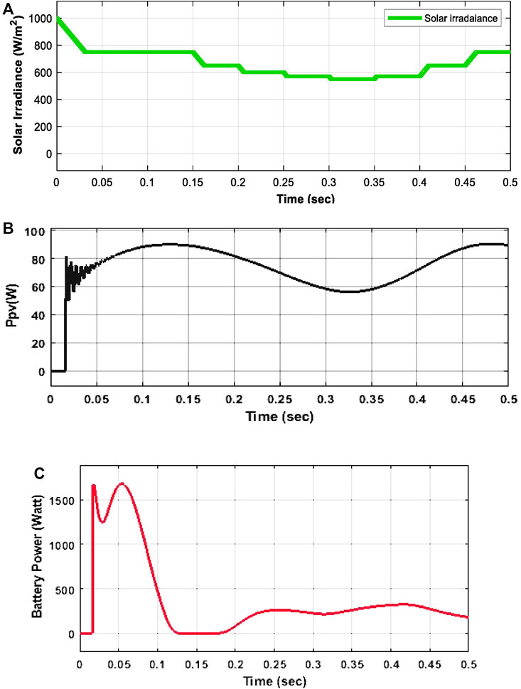
FIGURE 13. (A) Solar irradiance pattern (in W/m2). (B) Power of the solar PV module. (C) Battery power.
The dynamic response of the voltage of the PV module is shown in Figure 13B. The PV generation characteristic is displayed in Figure 13B and the resulting distributed energy of the PV module through controlled VSI boosts output and reduction of unwanted harmonics in the load side. Furthermore, it is observed the distributed energy of the particular PV module is certainly impacted by the variation of solar irradiance and maximize their value up to 10 kW.
Figure 13C displays the relative response of the battery charging energy provided to the distribution grid via a dc-link connection. Active response of the analyzed method is obtained within the variations of the solar power. It is noticed that if the PI control scheme is investigated together with the battery, then the effective energy is given directly into the distributed main grid. Furthermore, when the SC is generally absent, the distributed generated energy into the main grid fluctuates substantially.
4.2 Variation in the Capacity of SC
These subsections investigating the effect of different sizes of SC are used for stability evaluation. In Figure 14A, the relative dynamic response of the stored energy is given to distributed grid for three different ratings of SC. Three different supercapacitors with a capacity of 60/30/95 kW are typically used in the stability analysis of the HPGS.
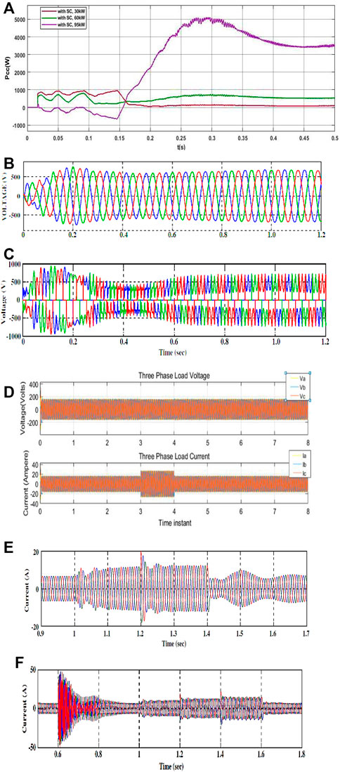
FIGURE 14. (A) Comparative dynamic stability performance of the different rating SC to the effectively stored energy into the distributed grid. (B) Solar PV module via DC-to-AC inverter during no-load scenario. (C) V characteristics of wind energy subsystem. (D) Measured three phase V and I waveforms under no load. (E) Current stability response of HPGS under RL load. (F) Current stability response of the HPGS with SC operation under RL load.
From the simulation results, validation of response characteristics illustrated in Figures 14B,C, it has resulted that at the 50 Hz constant frequency, under RL and without load conditions, the proposed HPGS generates an overrated RMS voltage of 960 V or 1.02 kV (peak). Now, the simulated loads are added at PCC through a DC bus system.
Here in Figure 14C, we can examine that specific voltage drops in the HPGS demonstrated at 0.25–0.6 s. After 0.6 s duration, the load will be removed, and we have noticed that the reduced rated voltage is now stabilized.
From Figure 14D, the stability of a grid-connected HPGS has been successfully investigated at no load; also, during 3–4 s, I waveforms tend to stabilize. To reduce the fluctuation of a connected grid system, a supercapacitor-based energy storage technology was deployed. Furthermore, a d-q control technique is proposed for maintaining the power flow balance and obtaining maximum power from an HPGS coupled to the grid system. The d-q based control scheme is proposed to suppress power variation from the distributed energy resources to the distribution grid, while maximum energy extracts were obtained through a P&O-based MPPT controller. The results presented for the power quality are considerably higher by enabling the integration of an effective distributed HES approach operated by the PI controller.
To stabilize the current drop phenomena, the proposed RL load is presented to the HPGS referred from Figure 14E. It was observed that SC was integrated with DC bus along with RL load at 0.67 s, as depicted from Figure 14F. When SC is placed into the HPGS along with sudden RL load, the proposed system maintained their current and frequency values at rated values of 425 V (RMS value) or 590 V (peak value). Furthermore, these results show that the optimal placement of SC by VSI voltage is controlled, even though the DC bus voltage is controlled. It is depicted that, in the current response, roughly transients are there because of switching time in the SC. Thus, nevertheless, of these slight transients, the simulated results show a stability enhancement approach in the performance of the proposed HPGS.
4.3 Power Quality Analysis of the Proposed HPGS
The grid-side harmonics of the proposed HPGS model is reduced, that is, 1.06% THD. Figure 15A shows the output power was ensured comparable with IEEE standards 519–2014 (Kanjiya et al., 2015). Since the voltage of the DC buses was modified by modifying the resonance frequency using a PI controller, it should also be specified that the recommended converter has the highest converter efficiency for boost operation.
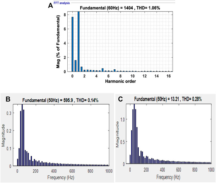
FIGURE 15. (A) THD analysis after synchronized grid voltage. (B) THD of proposed HPGS voltages under RL load. (C) THD of proposed HPGS current under RL load.
The FFT algorithm based THD of the V and I in the proposed simulated HPGS as shown in Figures 15B,C under the RL load scenario was examined as per the IEEE THD range (<5%) (Kanjiya et al., 2015).
Simulated results of the proposed PI control scheme conclude that the SC enables the HPGS to achieve the optimal implementation and limits reactive power at a steady state. The PI controller was utilized to achieve the active power flow through the DC link in the HPGS and stored SC energy to maintain the load level. The PI controller uses different modes to get optimal results from the HPGS.
5 Conclusion
This article has successfully contributed to the stable dynamic responses of SC and validated the power quality results for the proposed HPGS model. The designed wind PMSG coupled with a suitable solar PV module which supplied energy to an RL load through the controlled application of a VSI for DC/AC, a battery storage subsystem, a DC/DC boost converter, and an LCL based filter for harmonic elimination. The intermittent characteristics of wind speed and solar irradiation obtained from sunlight have no adverse effect over the integrated load and fed continuous stable load voltage and current profiles associated through the DC/AC inverter. During modeling eigenvalue analysis of the hybrid system, it was established that the designed SC has controlled damping oscillations and supplemented the stability of HPGS under the influence of sudden load changing operating conditions. The proposed dc-link voltage control strategy has improved the active power flow with the utilization of SC for HPGS under the influence of the different grid scenarios (weak/sudden load change). This article has analyzed the optimal oscillation control approach to enhance the dynamic grid performance and power quality control of HPGS under a scenario of a weak grid. Simulated results of HPGS have proven the effective utilization of the HPGS under a steady-state scenario. Analysis with the comparison of obtained results from the PI controller approach reveals that the transient/dynamic responses have better flexible controllability. The dc-link voltage controller can be robust for the wide range of grid voltage and impedance control under multi microgrid systems. The proposed novel controller approach is very efficient in controlling the constant bus voltage and fed ripples free power under the influence of sudden disturbances. So forth, the tuning of the proposed control scheme can be improved further to maintain the quality of power being supplied to AC loads integrated with remote control microgrid. In a future study, the real-time implementation of the HPGG model and its dynamic performance analysis to evaluate the optimal sizing of the HPGS with an intelligent controller (AL-Jumaili et al., 2021) scheme for the smart microgrid systems.
Data Availability Statement
The original contributions presented in the study are included in the article/supplementary material; further inquiries can be directed to the corresponding authors.
Author Contributions
Conceptualization and writing original draft; MA: formal analysis and editing; AP: investigation and supervision; SR. All authors listed have made a substantial, direct, and intellectual contribution to the work and approved it for publication.
Funding
This work was supported by the Qatar National Library.
Conflict of Interest
The authors declare that the research was conducted in the absence of any commercial or financial relationships that could be construed as a potential conflict of interest.
Publisher’s Note
All claims expressed in this article are solely those of the authors and do not necessarily represent those of their affiliated organizations, or those of the publisher, the editors and the reviewers. Any product that may be evaluated in this article, or claim that may be made by its manufacturer, is not guaranteed or endorsed by the publisher.
Acknowledgments
The authors are thankful to the journal editor and the anonymous reviewers for their insightful comments and suggestions which greatly improved the manuscript. Open Access funding provided by the Qatar National Library.
Abbreviations
IG, induction generator; PV, photovoltaic module;
References
Adil, M., Abdelkareem, M. A., Sayed, E. T., Rodriguez, C., Ramadan, M., and Olabi, A.-G. (2022). “Progress of Metal Chalcogenides in Supercapacitors,” in Encyclopedia of Smart Materials. Elsevier, 424–433. doi:10.1016/b978-0-12-815732-9.00153-4
Al-Dhalaan, S., Al-Majali, H. D., and O'Kelly, D. (1998). HVDC Converter Using Self-Commutated Devices. IEEE Trans. Power Electron. 13, 1164–1173. doi:10.1109/63.728343
Al-Jumaili, A. H. A., Mashhadany, Y. I. A., Sulaiman, R., and Alyasseri, Z. A. A. (2021). A Conceptual and Systematics for Intelligent Power Management System-Based Cloud Computing: Prospects, and Challenges. Appl. Sci. 11, 9820. doi:10.3390/APP11219820
Amir, M., and Khan, S. Z. (2021). “Assessment of Renewable Energy: Status, Challenges, COVID-19 Impacts, Opportunities, and Sustainable Energy Solutions in Africa,”. Energy Built Environ.3 (3), 348–362. doi:10.1016/j.enbenv.2021.03.002
Amir, M., and Srivastava, S. K. (2019). “Analysis of Harmonic Distortion in PV–Wind-Battery Based Hybrid Renewable Energy System for Microgrid Development. In: Mishra S., Sood Y., Tomar A. (eds). Applications of Computing, Automation and Wireless Systems in Electrical Engineering. Lecture Notes in Electrical Engineering553 (Singapore: Springer)
Amir, M., and Srivastava, S. K. (2018). “Analysis of MPPT Based Grid Connected Hybrid Renewable Energy System with Battery Backup,” in. 2018 Int. Conf. Comput. Power Commun. Tech. (Gucon) Sep. 2018, 903–907. doi:10.1109/GUCON.2018.8674902
Amir, M., and Zaheeruddin, “A. N. N. (2019). Based Approach for the Estimation and Enhancement of Power Transfer Capability. In: 2019 International Conference on Power Electronics, Control and Automation (ICPECA), 1–6. doi:10.1109/ICPECA47973.2019.8975665
Argyrou, M. C., Marouchos, C. C., Kalogirou, S. A., and Christodoulides, P. (2021). Modeling a Residential Grid-Connected PV System with Battery-Supercapacitor Storage: Control Design and Stability Analysis. Energ. Rep. 7, 4988–5002. doi:10.1016/j.egyr.2021.08.001
Armghan, H., Yang, M., Armghan, A., and Ali, N. (2020). “Double Integral Action Based Sliding Mode Controller Design for the Back-To-Back Converters in Grid-Connected Hybrid Wind-PV System,” Int. J. Electr. Power Energ. Syst. 127, 106655. doi:10.1016/j.ijepes.2020.106655
Bhat Nempu, P., and Jayalakshmi, N. S. (2020). “Coordinated Power Management of the Subgrids in a Hybrid AC–DC Microgrid with Multiple Renewable Sources. IETE J. Res. 2063. doi:10.1080/03772063.2020.1726829
Chandrasekaran, K., Selvaraj, J., Amaladoss, C. R., and Veerapan, L. (2021). “Hybrid Renewable Energy Based Smart Grid System for Reactive Power Management and Voltage Profile Enhancement Using Artificial Neural Network,” Energy Sources, Part A Recover. Util. Environ. Eff. 19, 2419–2442. doi:10.1080/15567036.2021.1902430
Dai, K., Wang, X., Yin, Y., Hao, C., and You, Z. (2016). Voltage Fluctuation in a Supercapacitor during a High-G Impact. Sci. Rep. 6, 38794. doi:10.1038/srep38794
Dong, R., Liu, S., Liang, G., An, X., and Xu, Y. (2019). Output Control Method of Microgrid VSI Control Network Based on Dynamic Matrix Control Algorithm. IEEE Access 7, 158459–158480. doi:10.1109/access.2019.2949909
Elbarbary, Z. M. S., and Alranini, M. A. (2021). Review of Maximum Power point Tracking Algorithms of PV System. Febe 1, 68–80. doi:10.1108/FEBE-03-2021-0019
Estévez-Bén, A. A., Alvarez-Diazcomas, A., Macias-Bobadilla, G., and Rodríguez-Reséndiz, J. (2020). “Leakage Current Reduction in Single-phase Grid-Connected Inverters - A Review. Appl. Sci. 10, 1–26. doi:10.3390/app10072384
Faessler, B. (2021). Stationary, Second Use Battery Energy Storage Systems and Their Applications: A Research Review. Energies 14, 2335. doi:10.3390/en14082335
Hlaili, M., and Mechergui, H. (2016). Comparison of Different MPPT Algorithms with a Proposed One Using a Power Estimator for Grid Connected PV Systems. Int. J. Photoenergy 2016, 1–10. doi:10.1155/2016/1728398
Hossain, M., Pota, H., Issa, W., and Hossain, M. (2017). Overview of AC Microgrid Controls with Inverter-Interfaced Generations. Energies 10, 1300. doi:10.3390/en10091300
Jadoon, Z. K., Shakeel, S., Saleem, A., Khaqan, A., Shuja, S., ul-Hasan, Q., et al. (2017). A Comparative Analysis of PID, Lead, Lag, Lead-Lag, and Cascaded Lead Controllers for a Drug Infusion System. J. Healthc. Eng. 2017, 1–13. doi:10.1155/2017/3153252
Kanjiya, P., Khadkikar, V., and Zeineldin, H. H. (2015). “Optimal Control of Shunt Active Power Filter to Meet IEEE Std. 519 Current Harmonic Constraints under Nonideal Supply Condition. IEEE Trans. Ind. Electron. 62, 724–734. doi:10.1109/TIE.2014.2341559
Kazimierczuk, M. K. (2000). Transfer Function of Current Modulator in PWM Converters with Current-Mode Control. IEEE Trans. Circuits Syst. 47, 1407–1412. doi:10.1109/81.883339
Kim, S. K., Jeon, J. H., Cho, C. H., Ahn, J. B., and Kwon, S. H. (2008). “Dynamic Modeling and Control of a Grid-Connected Hybrid Generation System with Versatile Power Transfer,” IEEE Trans. Ind. Electron.. 4, 1677–1688. doi:10.1109/TIE.2007.907662
Kollimalla, S. K., and Mishra, M. K. (2013). “Adaptive Perturb & Observe MPPT Algorithm for Photovoltaic System,” in 2013 IEEE Power and Energy Conference at Illinois (PECI). 2013, 42–47. doi:10.1109/PECI.2013.6506032
Krishan, O., and Suhag, S. (2020). Power Management Control Strategy for Hybrid Energy Storage System in a Grid‐independent Hybrid Renewable Energy System: a Hardware‐in‐loop Real‐time Verification. IET Renew. Power Generation 14, 454–465. doi:10.1049/iet-rpg.2019.0578
Kulkarni, S. H., Anil, T. R., and Gowdar, R. D. (2016). Wind Energy Development in India and a Methodology for Evaluating Performance of Wind Farm Clusters. J. Renew. Energ. 2016, 1–11. doi:10.1155/2016/6769405
Kumar, K., Alam, M., and Dutta, V. (2021). Energy Management Strategy for Integration of Fuel Cell-Electrolyzer Technologies in Microgrid. Int. J. Hydrogen Energ. 46, 33738–33755. doi:10.1016/j.ijhydene.2021.07.203
MNRE (2019). “Status of Solar Wind Renewable Energy in India,” Available at: https://efaidnbmnnnibpcajpcglclefindmkaj/viewer.html?pdfurl=https%3A%2F%2Fmnre.gov.in%2Fimg%2Fdocuments%2Fuploads%2Ffile_f-1608040317211.pdf&clen=7493391&chunk=true.
Naidu, B. R., Panda, G., and Chitti Babu, B. (2019). “Dynamic Energy Management and Control of a Grid-Interactive DC Microgrid System,” in Smart Power Distribution Systems. Elsevier, 41–67. doi:10.1016/b978-0-12-812154-2.00003-1
Ngo and Santoso, T. S. (2016). Improving Proportional-Resonant Controller for Unbalanced Voltage and Frequency Variation Grid,” in. 2016 IEEE/PES Transm. Distribution Conf. Exposition (T&d) May 2016, 1–5. doi:10.1109/TDC..7520071
Ni, F., Zheng, Z., Xie, Q., Xiao, X., Zong, Y., and Huang, C. (2021). “Enhancing Resilience of DC Microgrids with Model Predictive Control Based Hybrid Energy Storage System,” Int. J. Electr. Power Energ. Syst. 128, 106738. doi:10.1016/j.ijepes.2020.106738
Nwaigwe, K. N., Mutabilwa, P., and Dintwa, E. (2019). An Overview of Solar Power (PV Systems) Integration into Electricity Grids. Mater. Sci. Energ. Tech. 2, 629–633. doi:10.1016/j.mset.2019.07.002
Okundamiya, M. S. (2021). Size Optimization of a Hybrid Photovoltaic/fuel Cell Grid Connected Power System Including Hydrogen Storage. Int. J. Hydrogen Energ. 46, 30539–30546. doi:10.1016/j.ijhydene.2020.11.185
Ozdemir, S. (2016). Z-source T-type Inverter for Renewable Energy Systems with Proportional Resonant Controller. Int. J. Hydrogen Energ. 41, 12591–12602. doi:10.1016/j.ijhydene.2016.01.140
Patel, M. R. (2006). Wind and Solar Power Systems: Design, Analysis, and Operation, Second Edi. Taylor & Francis.
Patel, N., Kumar, A., Gupta, N., Ray, S., and Babu, B. C. (2020). Optimised PI‐4VPI Current Controller for Three‐phase Grid‐integrated Photovoltaic Inverter under Grid Voltage Distortions. IET Renew. Power Generation 14, 779–792. doi:10.1049/iet-rpg.2019.0507
Penalba, M., Cortajarena, J.-A., and Ringwood, J. (2017). Validating a Wave-To-Wire Model for a Wave Energy Converter-Part II: The Electrical System. Energies 10, 1002. doi:10.3390/en10071002
Pinto, S. J., and Panda, G. (2016). Improved Decoupled Control and Islanding Detection of Inverter-Based Distribution in Multibus Microgrid Systems. J. Power Elect. 16, 1526–1540. doi:10.6113/JPE.2016.16.4.1526
Ponnuru, S., Ashok Kumar, R., and Jothi Swaroopan, N. M. (2021). Intelligent Control and Power Management of Wind-Solar Integration of Renewable Energy Sources Using Microgrid. Mater. Today Proc. 45, 2323–2328. doi:10.1016/j.matpr.2020.10.687
Praveen Kumar, T., Subrahmanyam, N., and Sydulu, M. (2021). Power Flow Management of the Grid-Connected Hybrid Renewable Energy System: A PLSANN Control Approach. IETE J. Res. 67, 569–584. doi:10.1080/03772063.2019.1565950
Punna, S., Manthati, U. B., and Chirayarukil Raveendran, A. (2021). “Modeling, Analysis, and Design of Novel Control Scheme for Two-Input Bidirectional DC-DC Converter for HESS in DC Microgrid Applications,” Int. Trans. Electr. Energ. Syst. 10, 1–23. doi:10.1002/2050-7038.12774
Ravikumar., S., and Venkatanarayanan., S. D. (2020). GWO BASED CONTROLLING OF SEPIC CONVERTER IN PV FED GRID CONNECTED SINGLE PHASE SYSTEM. Microprocess. Microsyst., 103312. doi:10.1016/j.micpro.2020.103312
Salimi, M., Radmand, F., and Firouz, M. H. (2021). “Dynamic Modeling and Closed-Loop Control of Hybrid Grid-Connected Renewable Energy System with Multi-Input Multi-Output Controller,” J. Mod. Power Syst. Clean. Energ.. 1, 94–103. doi:10.35833/MPCE.2018.000353
Sanguesa, J. A., Torres-Sanz, V., Garrido, P., Martinez, F. J., and Marquez-Barja, J. M. (2021). A Review on Electric Vehicles: Technologies and Challenges. Smart Cities 4, 372–404. doi:10.3390/smartcities4010022
Sanki, P., Mazumder, S., Basu, M., Pal, P. S., and Das, D. (2021). Moth Flame Optimization Based Fuzzy-PID Controller for Power-Frequency Balance of an Islanded Microgrid. J. Inst. Eng. India Ser. B 102, 997–1006. doi:10.1007/s40031-021-00607-4
Sharma, R., and Suhag, S. (2018). Power Quality and Stability Improvement of Hybrid Energy System under Weak Grid Environment. Arab J. Sci. Eng. 43, 3065–3081. doi:10.1007/s13369-018-3109-2
Shayeghi, H., Monfaredi, F., Dejamkhooy, A., Shafie-khah, M., and Catalão, J. P. S. (2020). “Assessing Hybrid Supercapacitor-Battery Energy Storage for Active Power Management in a Wind-Diesel System,” Int. J. Electr. Power Energ. Syst. 125, 2021. doi:10.1016/j.ijepes.2020.106391
Soliman, M. A., Hasanien, H. M., Azazi, H. Z., El‐kholy, E. E., and Mahmoud, S. A. (2018). Hybrid ANFIS‐GA‐based Control Scheme for Performance Enhancement of a Grid‐connected Wind Generator. IET Renew. Power Generation 12, 832–843. doi:10.1049/iet-rpg.2017.0576
Sun, J., Zhang, H., Wang, Y., and Fu, M. (2021). Optimal Tracking Control of Switched Systems Applied in Grid-Connected Hybrid Generation Using Reinforcement Learning. Neural Comput. Applic 33, 9363–9374. doi:10.1007/s00521-021-05696-2
Teodorescu, P. (2011). Grid Converters for Photovoltaic and Wind Systems, First. John Wiley & Sons, Ltd.5. doi:10.1002/9780470667057.ch2
Toghani Holari, Y., Taher, S. A., and Mehrasa, M. (2020). “Power Management Using Robust Control Strategy in Hybrid Microgrid for Both Grid-Connected and Islanding Modes,” J. Energ. Storage 39, 102600. doi:10.1016/j.est.2021.102600
Urooj, S., Amir, M., Khan, A., and Tariq, M. (2021). An Adaptive Neuro-Fuzzy Based Methodology for Harmonic Analysis of a Power Transformer. 1, 1–10.
Urooj, S., Singh, T., Amir, M., and Tariq, M. (2020). Optimal Design of Power Transformer with Advance Core Material Using ANSYS Technique. Eur. J. Electr. Eng. Comput. Sci. 4, 1–17. doi:10.24018/ejece.2020.4.5.249
Wang, L., and Lin, T. J. (2007). “Stability and Performance of an Autonomous Hybrid Wind-PV-Battery System,” 2007 Int. Conf. Intell. Syst. Appl. Power Syst. ISAP 2007. doi:10.1109/ISAP.2007.4441622
Hoon, Y., Radzi, M. A. M., Hassan, M. K., and Mailah, N. F., “DC-link Capacitor Voltage Regulation for Three-phase Three-Level Inverter-Based Shunt Active Power Filter with Inverted Error Deviation Control,” Energies, Vol. 9, 7, 2016, doi:10.3390/en9070533
Zhang, L., Harnefors, L., and Nee, H.-P. (2010). “Power-Synchronization Control of Grid-Connected Voltage-Source Converters,” IEEE Trans. Power Sys. 25, 809–820. doi:10.1109/TPWRS.2009.2032231
Keywords: dynamic stability, HPGS, induction generator, photovoltaic array, supercapacitor, supply power grid, THD, smart grid
Citation: Amir M, Prajapati AK and Refaat SS (2022) Dynamic Performance Evaluation of Grid-Connected Hybrid Renewable Energy-Based Power Generation for Stability and Power Quality Enhancement in Smart Grid. Front. Energy Res. 10:861282. doi: 10.3389/fenrg.2022.861282
Received: 24 January 2022; Accepted: 14 February 2022;
Published: 10 March 2022.
Edited by:
Shabana Urooj, Princess Nourah bint Abdulrahman University, Saudi ArabiaReviewed by:
Krishnakumar R. Vasudevan, GE Global Research, IndiaAhmed AL-Jumaili, University of Fallujah, Iraq
Copyright © 2022 Amir, Prajapati and Refaat. This is an open-access article distributed under the terms of the Creative Commons Attribution License (CC BY). The use, distribution or reproduction in other forums is permitted, provided the original author(s) and the copyright owner(s) are credited and that the original publication in this journal is cited, in accordance with accepted academic practice. No use, distribution or reproduction is permitted which does not comply with these terms.
*Correspondence: Anjani Kumar Prajapati, ZWVkYWtwQGdtYWlsLmNvbQ==; Shady S. Refaat, c2hhZHkua2hhbGlsQHFhdGFyLnRhbXUuZWR1