- 1Key Laboratory of Fluid Transmission Technology of Zhejiang Province, Zhejiang Sci-Tech University, Hangzhou, China
- 2Hangzhou Weiguang Electronic Co., Ltd., Hangzhou, China
- 3Department of Application and Engineering, Zhejiang Economic and Trade Polytechnical, Hangzhou, China
A wear-ring is an important part of the centrifugal pump. The leakage flow in the wear-ring clearance and main flow at the impeller inlet form crossed mixed flows perpendicular to each other. Large eddies and shocks are produced at the intersection of the two flows due to great velocity difference and different directions, resulting in flow losses, unsteady flow, and even flow-induced vibration. Consequently, the pump performance, pressure pulsation and vibration, and other characteristics will be greatly affected. In this paper, 5 incident angles between the incident section of the wear-ring clearance and the circumferential direction of impeller inlet, i.e., the original angle (90°), 75°, 60°, 45°, and 30°, were formed with a low-specific-speed centrifugal pump as the study object. Unsteady flow calculation and fluid–structure interaction calculation were performed on centrifugal pumps with different wear-ring clearances; the effect of the incident angle of the wear-ring clearance on the distribution of pressure pulsation and vibration performance of centrifugal pump was analyzed. The results showed that the improved efflux angle of the wear-ring clearance could effectively weaken the impact disturbance of the leakage flow in the wear-ring clearance to the main flow at the inlet. Accordingly, the flow status at the inlet of the centrifugal pump was improved, flow losses were reduced, the efficiency of the centrifugal pump was improved, and the vibration amplitude and vibration energy of the pump were also reduced.
Introduction
The leakage flow in the wear-ring clearance and main flow at the impeller inlet form crossed mixed flows perpendicular to each other. Large eddies and shocks are produced at the intersection of the two flows due to great velocity difference and different directions, resulting in flow losses, unsteady flow, and even flow-induced vibration. Consequently, the pump performance, pressure pulsation and vibration, and other characteristics will be greatly affected. Wu et al. (Xianfang et al., 2021) studied the effect of the front and rear wear-ring clearance on the pump performance and investigated the changes in the pump performance by a test and numerical simulation. Yan et al. (Yan et al., 2019) found that the wear-ring clearance leakage seriously affects the pump performance. Adistiya et al. (Adistiya and Wijayanta, 2019) studied the effect of the wear-ring clearance by changing the clearance, so as to get higher efficiency. The study of Zheng et al. (Zheng et al., 2020) found that the changes in the wear-ring clearance cause a decrease in the lift, efficiency, and pressure pulsation of a centrifugal pump, and that the clearance efflux angle has a great influence on the pressure distribution at the impeller inlet. Liu et al. (Liu, 2014) found that the pressure distribution in the anterior clearance is greatly affected by the size and radial position of the wear-ring clearance. The study of Li et al. (Li, 2012) found that clearance expansion reduces the efficiency of the centrifugal pump, but the amplitude decreases as the viscosity increases. According to the study of DaqiqShirazi et al. (DaqiqShirazi et al., 2018), when the wear-ring clearance is small, disc friction efficiency has the greatest effect on the efficiency; with the increase of the wear-ring clearance, the volumetric efficiency decreases, but the friction efficiency increases, and the overall efficiency does not decrease significantly. Chen et al. (Chen et al., 2012) indicated that the reason for the decrease in the lift and efficiency of the centrifugal pump is as follows: a small wear-ring clearance reduces the internal turbulence and hydraulic loss, and the increase of clearance decreases the eccentric vortex. Gupta et al. (Gupta and Childs, 2006) established a compressible fluid model for leakage flow of the front and rear wear-ring clearance and obtained the dynamic performance of leakage flow. Zhang (Zhang et al., 2017) found that, within a certain clearance range, the clearance leakage has little effect on pressure fluctuation at the impeller inlet and in the center area; beyond this range, the fluctuation of the whole flow passage increases obviously, but clearance change has little effect on the fluctuation of a guide vane. Yu et al. (Yu, 2019) studied the effect of tip clearance on the performance of low-specific-speed mixed-flow pumps and found that the changes in the size of the tip clearance have a greater effect on the external performance under high flow. Anish et al. (Anish and Sitaram, 2017) found that pressure fluctuation is still controlled by the blade passing frequency in the clearance. Hao (Hao and Tan, 2018) studied the effect of different radial clearances on vibration noise by the fluid–structure interaction (FSI) method and found that increasing the radial clearance will not only reduce the efficiency but also reduce the vibration and noise. In addition to the effect of the wear-ring clearance on the efficiency, lift, and other performance of the pump, the leakage flow in the wear-ring clearance and main flow at impeller inlet form crossed mixed flows perpendicular to each other. Large eddies and shocks are produced at the intersection of the two flows due to great velocity difference and different directions, resulting in flow losses, unsteady flow, and even flow-induced vibration (Sergio and Francesco, 2016; Norrbin et al., 2017; Shi et al., 2017-7). At present, the studies on the wear-ring clearance of centrifugal pumps mainly focus on the effect of clearance flow on the pump performance, and the effect on pressure pulsation and vibration performance is seldom involved. In this paper, the pressure pulsation and vibration performance of the pump under different incident angles were studied by changing the incident angle of the wear-ring clearance of the centrifugal pump. This study showed that the improved efflux angle of the wear-ring clearance could effectively weaken the impact disturbance of the leakage flow in the wear-ring clearance to the main flow at the inlet. Accordingly, the flow status at the inlet of the centrifugal pump was improved, flow losses were reduced, the efficiency of the centrifugal pump was improved, and the vibration amplitude and vibration energy of the pump were also reduced.
Centrifugal Pump Model
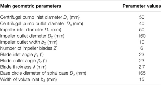
In this paper, the speed of the model pump n = 2,950 r/min, the design flow Qd = 11 m3/h, and the rated lift Hd = 40 m. The pump inlet diameter Ds = 50 mm, the outlet diameter Do = 40 mm, the impeller inlet diameter D1 = 50 mm, the impeller outlet diameter D2 = 160 mm, the impeller outlet width b2 = 10 mm, the number of impeller blades Z = 6, the blade inlet angle β1 = 23°, the blade outlet angle β2 = 23°, the blade thickness δ = 2.7 mm, the volute base circle diameter Db = 165 mm, and the volute inlet width b2 = 15 mm. The model pump is shown in Figure 1. The main geometric parameters of the prototype pump are shown in Table 1.

FIGURE 1. Diagram of computational domain of flow field and rotor. (A) Computational domain of flow field. (B) Computational domain of rotor.
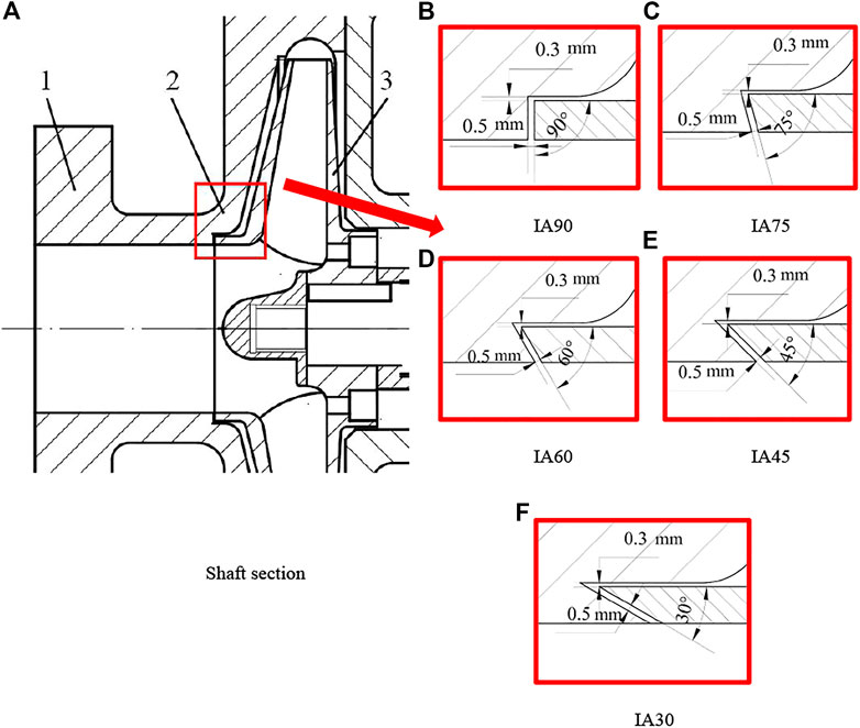
In this paper, the incident angle of the wear-ring clearance was changed to 90° (IA90), 75° (IA 75), 60° (IA 60), 45° (IA 45), and 30°(IA 30) by changing the outer contour of 1-pump and 2-impeller wear-rings; the same wear-ring clearance (0.3 mm) and same incident position were maintained; the diagram of the incident angle of different wear-ring clearances is shown in Figure 2.
Numerical Calculation Method and Test Apparatus
Numerical Calculation Method
The model in this paper was the SST k–ω model. When the compressibility of the fluid is not considered, this model can be expressed as (Menter, 1992; Versteeg and Malalasekera, 1995)
where
In this paper, the velocity inlet and free outflow were used in the numerical calculation of the whole flow field of the centrifugal pump. The walls of the impeller flow domain and those in contact with the solid region of the impeller were set to rotate walls, the walls of other flow domains were set to stationary walls, and all walls were set to smooth walls. The coupling between speed and pressure was realized by the SIMPLEC algorithm. The second-order upwind and central difference scheme were adopted for the spatial dispersion of the convective term and diffusive term, respectively. In the unsteady calculation of the whole flow field, the time step of every 1° rotation of the impeller was taken as a time step, and a rotation cycle contained 360 time steps in total. The speed of the model pump was 2,950 r/min, the time step was 5.64972 × 10⁻⁵ s, and the convergence residual accuracy of each physical quantity was set to 10−5.
In the FSI calculation, the calculation of the three parts, the flow field, solid structure field, and data transfer of the FSI surface, converged. The convergence criterion in the data transfer of the FSI surface was
where,
The criterion for determining the convergence of the FSI load data transfer is:
Figure 3 shows a diagram of the flow field domain and rotor mesh. Figures 4A,B are mesh independence verification diagrams of the flow field domain and impeller rotor domain, respectively. According to the mesh independence verification, the number of mesh cells finally selected herein for the flow field and rotor domain was 6.06 × 10⁶ and 15.31 × 10⁴, respectively.

FIGURE 3. Diagram of flow field domain and rotor mesh. (A) Impeller flow. (B) Rotor structure mesh. (C) Whole flow field mesh. (D) Partial enlarged drawing.
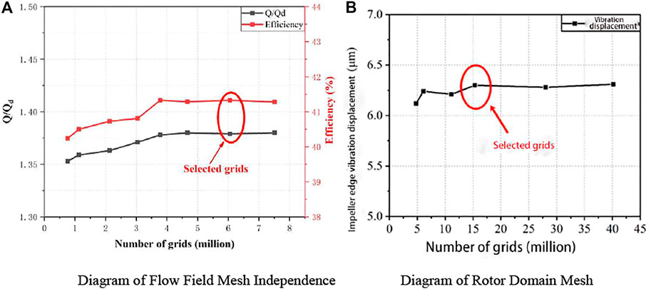
FIGURE 4. Diagrams of mesh independence verification. (A) Diagram of flow field mesh independence. (B) Diagram of rotor domain mesh.
Test Apparatus
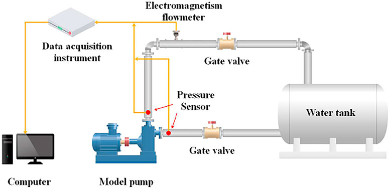
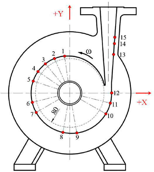
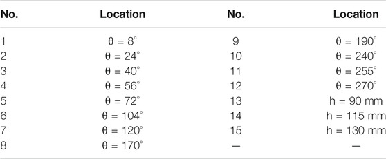
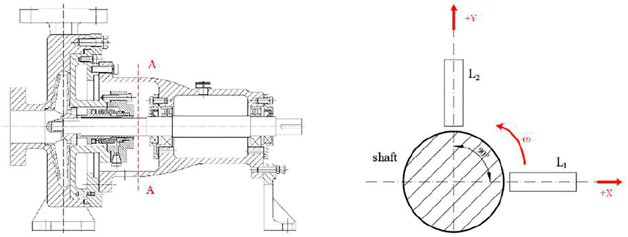
The test apparatus and piping system are shown in Figure 5. The pressure pulsation sensor used herein is a high-frequency dynamic pressure sensor. Its model is GYS-I, its measuring range is -0.01–1 MPa, its accuracy is 0.2, and its frequency response is 10 kHz. The installation position of the sensor is shown in Figure 6 and Table 2. In this paper, a non-contact electric vorticity sensor with a sensitivity of 4 mV/μm and a range of 0–2 mm was used to measure the vibration displacement of the centrifugal pump. The installation position of the vibration sensor is shown in Figure 7.
Results and Discussion
Effect of Wear-Ring Incident Angle on Pump Pressure Pulsation
Figure 8 shows the comparison of the experimental value and calculation results of the pressure pulsation of the prototype pump (IA90) at different observation points under design conditions. According to the figure, under the design flow (11 m3/h), the main frequency of pressure pulsation at different observation points was near the blade frequency, and the maximum amplitude of the experimental value and calculation results was at observation point EP15. In general, under design conditions, the experimental value and calculation results of pressure pulsation have a consistent distribution trend, with the main frequency at the blade frequency (with an error of only 0.2%). This verified that the numerical calculation method used herein is accurate and reliable.
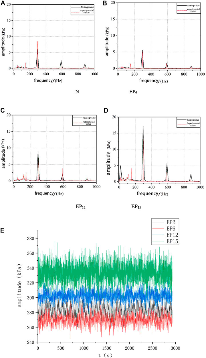
FIGURE 8. Comparison of experimental value and calculation results of pressure pulsation of the prototype pump (IA90) at different observation points under design conditions and the original pressure signal.
In order to further analyze the flow status in the wear-ring clearance and at the impeller inlet, 4 observation points were arranged in the wear-ring clearance and on the near wall of the impeller inlet, respectively. The position of observation points is shown in Figure 9. SP1∼SP4 are observation points in the wear-ring clearance; SP5∼SP8 are observation points on the near wall of the impeller inlet.
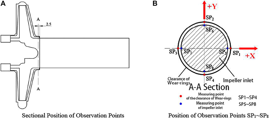
FIGURE 9. Diagram of position of observation points for wear-ring pressure pulsation. (A) Sectional position of observation points. (B) Position of observation points SP1∼SP8.
Figure 10 shows the frequency domain distribution at observation points in the wear-ring clearance under the design flow and different incident angles of the wear-ring clearance. This figure shows that the pressure pulsation frequency domain of centrifugal pumps with the different incident angles of the wear-ring clearance also shows strong asymmetry. The frequency domain of pressure pulsation is mainly in the low-frequency band. The intermediate frequency is mainly the frequency multiplier (295 Hz) of the blade passing frequency. The reason for this is that after a long anterior flow domain, the flow gradually becomes orderly and the high-frequency pulsation is gradually weakened. The main frequency of each observation point is different and is mainly concentrated in the multiplier and shaft frequency multiplier and shaft frequency. The pulsation amplitudes in each frequency domain decrease with the decrease of the incident angle of the wear-ring clearance. The reason is that the decrease of the incident angle of the wear-ring clearance makes the flow in the wear-ring clearance more orderly. Compared with the maximum amplitude of pressure pulsation of IA90, the maximum amplitude of pressure pulsation of IA75, IA60, IA45, and IA30 decreased by 5.9%, 44.3%, 49.6%, and 42.7%, respectively.
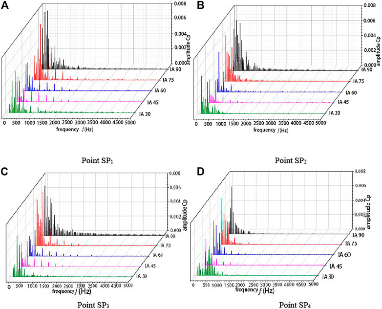
FIGURE 10. Comparison of shaft frequency and blade frequency of pressure pulsation in wear-ring clearance under design conditions and different incident angles of wear-ring clearance. (A) Point SP1. (B) Point SP2. (C) Point SP3. (D) Point SP4.
Figure 11 shows the comparison of the RMS values of pressure pulsation in the wear-ring clearance under the design conditions and different incident angles of the wear-ring clearance. It can be seen from Figure 11 that compared with IA90, the RMS values in each band of IA75 did not change greatly. This indicates that IA75 has no obvious effect on pressure pulsation in the wear-ring clearance. However, compared with the IA90 model, the amplitude of pressure pulsation in the low-frequency band of IA60, IA45, and IA30 models was greatly improved, while the amplitude of the low-frequency RMS value decreased by 30.8%, 44.0%, and 37.4%, respectively. The amplitude of the RMS value of pressure pulsation in the middle frequency band of IA60, IA45, and IA30 models also decreased significantly and was 22.4%, 29.3%, and 32.2% lower than that of the IA90 model, respectively. The amplitude of the RMS value of pressure pulsation in the high-frequency band of the three models was also greatly improved and was 12.4%, 9.3%, and 24.2% lower than that of the IA90 model. Thus, it can be seen that the decrease of the incident angle of the wear-ring clearance can effectively reduce the amplitude of pressure pulsation in the low-frequency band and has little effect on the amplitude of pressure pulsation in the high-frequency band.

FIGURE 11. Comparison of RMS values of pressure pulsation in wear-ring clearance under different incident angles of wear-ring clearance. (A) Low band. (B) Mid band. (C) High band.
Effect of Wear-Ring Incident Angle on Pump Vibration Performance
Figure 12 shows the comparison of time domain and frequency domain of the results of the vibration displacement experiment and numerical simulation of the IA90 centrifugal pump. According to Figure 12, the time–domain diagram of vibration displacement shows obvious periodicity and has six peaks and troughs; experimental values are slightly greater than calculated ones; the amplitude is mainly concentrated in the shaft frequency and blade frequency. The experimental values at the design flow and the FSI calculation results have a consistent trend, which indicates that the results of the FSI calculation adopted in this paper are relatively accurate.
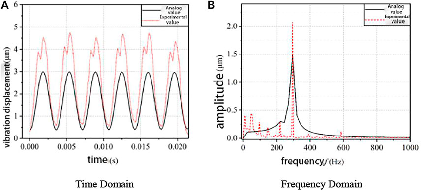
FIGURE 12. Time domain and frequency domain of simulated vibration and experimental vibration. (A) Time domain (B) Frequency domain.
Figure 13 shows the distribution diagram of the time domain and frequency domain of radial force on the pump impeller under the design flow and different incident angles. As shown in Figure 13C, the radial force on the impeller shows obvious periodicity; the decrease of the incident angle of the wear-ring clearance will gradually decrease the radial force on the impeller, and the pulsation amplitude of the radial force will also gradually decrease; however, from the frequency domain distribution of the radial force, the changes in the incident angle of the wear-ring clearance have a greater influence on the pulsation amplitude of the radial force at the shaft frequency and have a minor influence on the pulsation amplitude of the radial force at the blade frequency.
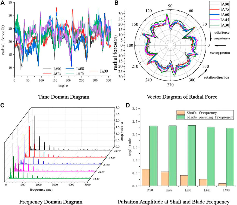
FIGURE 13. Time domain diagram and frequency domain diagram of radial force of centrifugal pump under different wear-ring incident angles and the design flow. (A) Time domain diagram. (B) Vector diagram of radial force. (C) Frequency domain diagram. (D) Pulsation amplitude at shaft and blade frequency.
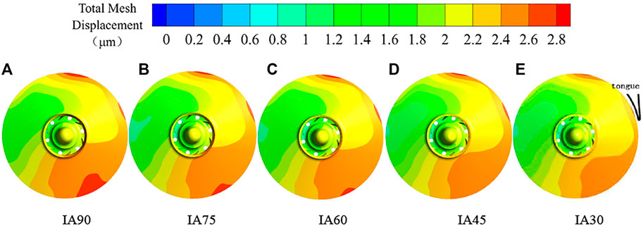
Figure 14 shows the overall vibration displacement diagram of the impeller rotor system of a centrifugal pump under different incident angles of the wear-ring clearance at t = 0.02 s. It can be seen from the figure that the maximum vibration displacements of centrifugal pumps with different incident angles of the wear-ring clearance appeared at the outer edge of the impeller, mainly at the highest and lowest point along the gravity direction and at the cutwater, and the minimum displacements appeared at the furthest distance from the cutwater. The maximum vibration displacement of IA90 under the original incident angle of the wear-ring clearance was 2.78 μm, while the vibration displacement of IA75 was slightly greater and was 2.72 μm. The maximum vibration displacement of IA60, IA45, and IA30 gradually decreased with the decrease of the incident angle of the wear-ring clearance. Moreover, the average of the deformed area decreased significantly; the maximum vibration displacement was 2.63, 2.59 and 2.55 μm, respectively. This shows that the decrease of the incident angle of the wear-ring clearance can effectively inhibit the vibration of the centrifugal pump impeller.
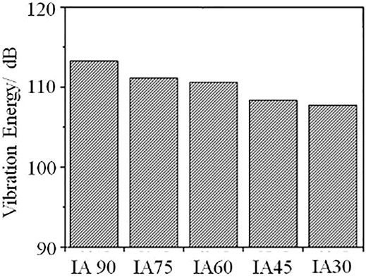
In order to further study the vibration performance of the centrifugal pump, the root mean square of the vibration power spectrum signal was calculated and was defined as the vibration energy RMS [1,66]. Figure 15 shows the vibration energy distribution of the impeller under different incident angles. As shown in this figure, the changes in the incident angle of the wear-ring clearance have a certain effect on the vibration energy of the pump. The vibration energy of the pump impeller gradually decreases and is inhibited to some extent with the gradual decrease of the wear-ring incident angle.
Conclusion
In this paper, IA30 is the best case of clearance shape from the analyzed ones; the pressure pulsation and vibration performance of the centrifugal pump under 5 different incident angles of the wear-ring clearance were analyzed by calculating the unsteady flow and FSI in the whole flow field of the centrifugal pump. The main conclusions are as follows:
1) Small incident angles of the wear-ring clearance will weaken the impact and disturbance of the wear-ring jet flow on the main flow, thus reducing the pressure pulsation of the pump, and the smaller the incident angle, the smaller the pressure pulsation amplitude.
2) The decrease of the incident angle of the wear-ring clearance can effectively reduce the amplitude of pressure pulsation in the low-frequency band and has little effect on the amplitude of pressure pulsation in the high-frequency band.
3) The analysis of the radial force on the impeller and vibration displacement and vibration energy of the impeller showed that the decrease of the incident angle of the wear-ring clearance will decrease the radial force on the impeller and also inhibit the vibration amplitude and vibration energy of the impeller.
4) The smaller the incident angle of the orifice ring gap, the higher the head and efficiency. This is because with the decrease of the incident angle of the orifice ring gap, the leakage of the front orifice ring gap decreases gradually, which improves the volumetric efficiency and thus the head and efficiency.
Data Availability Statement
The raw data supporting the conclusion of this article will be made available by the authors, without undue reservation.
Author Contributions
XJ and JY conceived of the presented idea. XJ developed the theory and performed the computations. JY encouraged XJ to investigate and supervised the findings of this work. BL, LZ, and ZZ were involved in planning and supervised the work, All authors discussed the results and contributed to the final manuscript.
Funding
This work was supported by the National Natural Science Foundation of China (Grant No. 51906221) and the Joint Fund of Zhejiang Natural Science Foundation (Grant No. LZY21E060002).
Conflict of Interest
BL was employed by the company Hangzhou Weiguang Electronic Co. Ltd.
The remaining authors declare that the research was conducted in the absence of any commercial or financial relationships that could be construed as a potential conflict of interest.
Publisher’s Note
All claims expressed in this article are solely those of the authors and do not necessarily represent those of their affiliated organizations, or those of the publisher, the editors and the reviewers. Any product that may be evaluated in this article, or claim that may be made by its manufacturer, is not guaranteed or endorsed by the publisher.
References
Adistiya, Suryana., and Wijayanta, A. T. (2019). Effect of Clearance gap on Hydraulic Efficiency of Centrifugal Pump. THE 4TH INTERNATIONAL CONFERENCE INDUSTRIAL, MECHANICAL, ELECTRICAL, CHEMICAL ENGINEERING 5. doi:10.1063/1.5098228
Anish, S., and Sitaram, N. (2017). Computational Study of Radial gap Effect between Impeller and Diffuser on the Unsteadiness of Vaned Diffuser in a Centrifugal Compressor. J. Mech. Sci. Technol. 31 (11), 5291–5298. doi:10.1007/s12206-017-1023-2
Chen, B., Li, X., and Zhu, Z. (2022a). Time-Resolved Particle Image Velocimetry Measurements and Proper Orthogonal Decomposition Analysis of Unsteady Flow in a Centrifugal Impeller Passage. Front. Energ. Res. 9. doi:10.3389/fenrg.2021.818232
Chen, B., Li, X., Zhu, Z., and Zhu, Zu. Chao. (2022b). Investigations of Energy Distribution and Loss Characterization in a Centrifugal Impeller through PIV experiment. Ocean Eng. 247 (2022), 110773. doi:10.1016/j.oceaneng.2022.110773
Chen, S. X., Pan, Z. Y., Wu, Y. L., and Zhang, D. Q. (2012). Simulation and experiment of the Effect of Clearance of Impeller Wear-Rings on the Performance of Centrifugal Pump. IOP Conf. Ser. Earth Environ. Sci. 15, 072017. doi:10.1088/1755-1315/15/7/072017
DaqiqShirazi, M., Torabi, R., Riasi, A., and Nourbakhsh, S. A. (2018). The Effect of Wear Ring Clearance on Flow Field in the Impeller Sidewall gap and Efficiency of a Low Specific Speed Centrifugal Pump. ARCHIVE Proc. Inst. Mech. Eng. C J. Mech. Eng. Sci. 1989-1996 (vols 203-210) 232 (17), 3062–3073. doi:10.1177/0954406217729420
Gupta, M. K., and Childs, D. W. (2006). Rotordynamic Stability Predictions for Centrifugal Compressors Using a Bulk-Flow Model to Predict Impeller Shroud Force and Moment Coefficients[J]. J. Eng. Gas Turbines Power 132 (9), 1211–1223. doi:10.1115/1.2720519
Hao, Y., and Tan, L. (2018). Symmetrical and Unsymmetrical Tip Clearances on Cavitation Performance and Radial Force of a Mixed Flow Pump as Turbine at Pump Mode. Renew. Energ. 127 (NOV), 368–376. doi:10.1016/j.renene.2018.04.072
Li, W. G. (2012). An Experimental Study on the Effect of Oil Viscosity and Wear-Ring Clearance on the Performance of an Industrial Centrifugal Pump[J]. J. Fluids Eng. 134 (1), 014501. doi:10.1115/1.4005671
Liu, Houlin. (2014). Investigation into Transient Flow in a Centrifugal Pump with Wear Ring Clearance Variation [J]. Adv. Mech. Eng. 6, 354–359. doi:10.1155/2014/693097
Menter, F. R. (1992). Influence of Freestream Values on K-ω Turbulence Model Predictions. AIAA J. (6), 1651–1659. doi:10.2514/3.11115
Norrbin, C. S., Childs, W. D., and Phillips, S. (2017). Including Housing-Casing Fluid in a Lateral Rotordynamics Analysis on Electric Submersible Pumps. J. Eng. Gas Turbines Power Trans. Asme. doi:10.1115/gt2016-58087
Sergio, Baragetti., and Francesco, V. (2016). Effects of Geometrical Clearances, Supports Friction, and Wear Rings on Hydraulic Actuators Bending Behavior. Math. Probl. Eng. 2016, 1–17.
Shi, W., Gao, X., Zhang, Q., Zhang, D., and Ye, D. (2017-7-01201). Numerical Investigations on Effect of Wear-Ring Clearance on Performance of a Submersible Well Pump. Adv. Mech. Eng. 97 (7), 168781401770415. doi:10.1177/1687814017704155
Versteeg, H. K., and Malalasekera, W. (1995). An Introduction to Computational Fluid dynamics[M]. British: Longman Group Ltd.
Xianfang, W., Xinlai, D., Minggao, T., and Houlin, L. (2021). Experiment and Simulation about the Effect of Wear-Ring Abrasion on the Performance of a marine Centrifugal Pump. Adv. Mech. Eng. 13, 168781402199811. doi:10.1177/1687814021998115
Yan, J., Zuo, Z., Guo, W., Hou, H., Zhou, X., and Chen, H. (2019). Influences of Wear-Ring Clearance Leakage on Performance of a Small-Scale Pump-Turbine. Proc. Inst. Mech. Eng. A: J. Power Energ. 234, 454–469. doi:10.1177/0957650919865052
Yu, Zhiyi. (2019). Numerical Analysis for the Effect of Tip Clearance in a Low Specific Speed Mixed-Flow Pump. Adv. Mech. Eng. 11, 3. doi:10.1177/1687814019832222
Zhang, W., Yu, Z., and Zhu, B. (2017). Influence of Tip Clearance on Pressure Fluctuation in Low Specific Speed Mixed-Flow Pump Passage. Energies 10 (2), 148. doi:10.3390/en10020148
Keywords: incident angle, wear-ring clearance, pressure pulsation, vibration performance, vibration energy, centrifugal pump
Citation: Jia X, Yu J, Li B, Zhang L and Zhu Z (2022) Effect of Incident Angle of Wear-Ring Clearance on Pressure Pulsation and Vibration Performance of Centrifugal Pump. Front. Energy Res. 10:861134. doi: 10.3389/fenrg.2022.861134
Received: 24 January 2022; Accepted: 21 February 2022;
Published: 29 March 2022.
Edited by:
Lei Tan, Tsinghua University, ChinaReviewed by:
Alin Bosioc, Politehnica University of Timișoara, RomaniaAly Abdelbaky Elbatran, Arab Academy for Science, Technology and Maritime Transport (AASTMT), Egypt
Copyright © 2022 Jia, Yu, Li, Zhang and Zhu. This is an open-access article distributed under the terms of the Creative Commons Attribution License (CC BY). The use, distribution or reproduction in other forums is permitted, provided the original author(s) and the copyright owner(s) are credited and that the original publication in this journal is cited, in accordance with accepted academic practice. No use, distribution or reproduction is permitted which does not comply with these terms.
*Correspondence: ZuChao Zhu, emh1enVjaGFvMDFAMTYzLmNvbQ==
 XiaoQi Jia
 Jilin Yu1
 Li Zhang
 ZuChao Zhu