 Zhiwei Jia
 Yihong Tian
 Zheng Liu
94% of researchers rate our articles as excellent or good
Learn more about the work of our research integrity team to safeguard the quality of each article we publish.
Find out more
ORIGINAL RESEARCH article
Front. Energy Res., 25 April 2022
Sec. Smart Grids
Volume 10 - 2022 | https://doi.org/10.3389/fenrg.2022.860461
This article is part of the Research TopicAdvanced Digital Technologies in Digitalized Smart GridView all 13 articles
Accurate evaluation of the cable trench condition is the key to realizing its intelligent operation and maintenance, and the intelligent cable trench inspection robot is a reliable information acquisition method for the condition assessment of cable trench. According to task requirements and site’s environment, an intelligent inspection robot is designed. The crawler-type motion mechanism is determined based on the demand for sizes and obstacle-surmounting. Cartographer SLAM technology is used to map the underground cable trench environment, and a path planning method combined with the improved A∗ algorithm and dynamic window method (DWA) is presented. Multiple sensors are equipped on this robot, and various kinds of information are obtained. Based on the information obtained, a condition assessment method of an underground cable trench is proposed. An extension neural network model is constructed to assess air quality. Channel capacity and ground flatness are calculated to evaluate the internal structure of the cable trench. The water depth and water surface area are comprehensively used to evaluate the hazard of water accumulation. The evaluation results are used to realize the linkage control of the cable trench’s operation and maintenance. A field test shows that the intelligent inspection robot can reliably obtain seven kinds of information from the underground cable trench, and the proposed condition evaluation method can assess the condition of the cable trench and provide four kinds of suggestions for potential hazards.
The underground cable trench is a facility to accommodate multi-circuit power cables and accessories. It has the function of a power cable joint space and can provide a large amount of power to major industrial complexes and high-load urban areas. Tunnel pipelines, public pipelines, and open cable pipelines are being built (Kang et al., 2018). However, harmful gases which are easy to accumulate in the cable trench, coupled with the discharge caused by cable insulation aging, could lead to explosion and fire (Liu and Yin, 2007). Furthermore, the probability of this danger gradually increases over time. So it is very important to find and eliminate these hidden dangers as soon as possible for the safe operation of the power system (Commission of the European Communities, 2003). However, the internal environment of the underground cable trench is complex, the space is narrow, high-voltage lines on both sides are densely distributed, and the ground is usually not hardened, which makes manual inspection extremely dangerous and difficult. Therefore, online detection of cable trench’s working state plays a vital role in improving the stability and reliability of power system operation (Jongen et al., 2012; Hepburn et al., 2016).
In the early environmental safety monitoring for the underground cable trench, fixed monitoring equipment was used to measure some parameters in the trench (Siddiqui et al., 2017). Due to the large length and span of the cable trench, monitoring blind areas always existed in these situations, which could not effectively reflect the operation state of the overall cable environment. Some research works have been conducted on inspection robots for cable trenches. A remote-controlled cable trench tunnel monitoring robot designed by Sun et al. (2021) is inconvenient to operate in a narrow cable trench environment. Yijiahe Technology Co., Ltd. has developed an inspection robot for substations (Xing et al., 2018), but the volume is very large for the narrow space of the underground cable trench and is only suitable for use in a more open space. The underground cable trench robot designed by the Changsha University of Technology can realize the inspection function (Ling et al., 2020), but the designed mapping method has a poor effect in the cable trench environment, which affects the subsequent navigation work.
The diagnosis of the state of the cable trench internal environment is the ultimate requirement of an inspection robot. Wu and Zhang, (2014) used the corresponding sensors integrated into the monitoring device of low-voltage distribution equipment to measure the surface temperature of the incoming and outgoing lines of the distribution box and the water level of the cable trench and to analyze the cable trench environment and obtain the fault assessment. Acquiring and analyzing the actual values of thermal resistance and diffusion coefficient of soil around the power cable, Lyall et al. (2000) evaluated temperature distribution inside the cable trench in real time. The “hot spots” inside the cable trench are predicted and timely prevented in this manner. The BP neural network was applied to monitor the temperature and humidity of the internal environment of the underground cable trench in real time, and the internal environment assessment of the underground cable trench was realized (Song, 2015). Infrared thermal imaging data were gathered and transmitted to the adaptive neuro-fuzzy inference system (ANFIS) of the remote terminal unit, and a support vector machine (SVM) classifier was used to evaluate internal fault information of the cable trench (Pal et al., 2017). These aforementioned research studies assess the state of the underground cable trench and similar scenes in one or more aspects, and they mainly collect data through fixed monitoring equipment, as well as few sensors, which leads to incomplete signals and half results.
A substation inspection robot (Lu et al., 2017) integrates multiple sensors to perform fault monitoring, including the appearance image of cable equipment, sound of running equipment, and temperature of equipment joints, but no assessment method is mentioned. There is little research on the internal environment assessment method of the underground cable trench based on inspection robots at home and abroad. Since the robot carries multiple sensors to monitor complex environmental information inside the cable trench in the inspection process, if only relying on manual subjective evaluation of a certain amount of monitoring, this inspection is slow, has low credibility, and even ignores larger faults. Therefore, the consideration of engineering safety is far from enough (Wang et al., 2012).
During the task of automatic inspection, the inspection robot consumes a lot of memory in the fuselage computer. At the same time, in the process of moving, it will continuously collect the data from infrared cameras, high-definition cameras, and gas sensors around the cable trench and transmit the data to the remote cloud platform for data processing to obtain the evaluation results of the cable trench. However, remote sending and receiving of a large amount of data require sufficient connectivity, which is not always true in reality, and the delay and reliability of service processing are difficult to guarantee (Patel et al., 2017). Edge computing aims to provide elastic services with low latency and high bandwidth efficiency (Premsankar et al., 2018). To solve the problem of limited edge resources, models are deployed on the edge and cloud, respectively, through model segmentation technology for collaborative reasoning (Li et al., 2018). Taking the SLAM algorithm of a mobile robot as an example, the need to use edge nodes for computing offload on a remote cloud or a local robot was discussed in Dey and Mukherjee (2016). In this study, the edge server was placed at each node of the cable trench to form a distributed management system of the whole cable trench edge.
The on-site experiments performed on the edge intelligent evaluation system based on the underground cable trench inspection robot show that an inspection robot which can adapt to the environment is designed in this study. According to the characteristics of the underground cable trench environment, the condition assessment of the cable trench is performed by multi-sensor information fusion. Our contributions are as follows:
(1) An automatic navigation system was designed according to the constraints of the inspection robot in the underground cable trench environment, and the improved global path A* algorithm and the local path DWA algorithm were fused by an improved fusion scheme. Compared with the traditional fusion path algorithm, the detection speed of the improved fusion algorithm proposed in this study increased by 21%, and the total path became shorter. On-site experiments verified the superiority of the path planning method.
(2) In the process of robot inspection, we evaluated the underground cable trench using the multi-sensor fusion method comprehensively. The indexes of air quality, internal structure, and ponding hazards of the underground cable trench were calculated respectively, and the underground cable trench from these three dimensions was assessed. Furthermore, the linkage control strategy was designed according to the assessment results.
The remainder of this article is organized as follows. The structure of our robot structure is shown in Inspection Robot Systems. The autonomous navigation system in the underground cable trench is described in The Overall Scheme of the Autonomous Navigation Obstacle Avoidance System. The condition assessment method is proposed in Condition Assessment of the Underground Cable Trench Based on Edge Intelligence. The experimental results and conclusion are presented in Analysis of Actual Site Results and Conclusion, respectively.
To meet the strict requirements of the small and complex internal environment of the underground cable trench, such as the volume and climbing ability of the robot, the external walking mode of the cable trench inspection robot is designed as a crawler-type double drive. The crawler-type double drive has a good grasping ability and can climb the slope. The double drive mode connects the front and rear wheels for driving, which has advantages such as low power consumption, small volume, ease to control, and many more. The actual measured values of vehicle body parameters are as follows: length, width, and height: 500 × 300 × 120 mm; chassis dead weight: 8.45 kg; maximum load: 30 kg; maximum climbing angle: 35°; maximum obstacle crossing: 90 mm; and maximum span: 250 mm. The actual experiment shows that the internal environment of the underground cable trench is good.
The inspection robot needs to perform multiple tasks and assess the overall internal environment of the underground cable trench. According to the inspection task and environmental constraints, the cable trench intelligent inspection robot needs to have the following four modules:
(1) Visual module. Infrared thermal imaging and a high-definition camera are used to judge any visual anomaly inside the cable trench.
(2) Multi-sensor gas detection module. This could accurately reflect the concentration of harmful gases and combustible gases in the air of the underground cable trench.
(3) Automatic navigation module. Based on the robot operating system (ROS), the data environment of the laser radar and gyroscope is used to map and locate, and the path planning is designed to realize automatic navigation.
(4) Evaluation module. The underground cable trench diagnosis system based on edge intelligence proposed in this study is used to evaluate the internal environment of the cable trench.
Aiming at the requirements of multi-sensor information acquisition and a multitask cooperative work of the inspection robot, the system structure of the intelligent inspection robot for the underground cable trench is designed (as shown in Figure 1). The system uses multi-CPU collaborative work architecture to improve its data processing capability. The laser radar is chosen to provide positioning and mapping information. The core information calculation module adopts the core main control board of NVIDIA, equipped with an ROS operating system to provide the system platform to realize the autonomous navigation algorithm. The infrared imager, high-definition camera, and other visual sensors are also connected to the main control board of NVIDIA for processing to realize the information reading of infrared thermal imaging and high-definition images. The video data stream is uploaded to the operating terminal through WLAN.
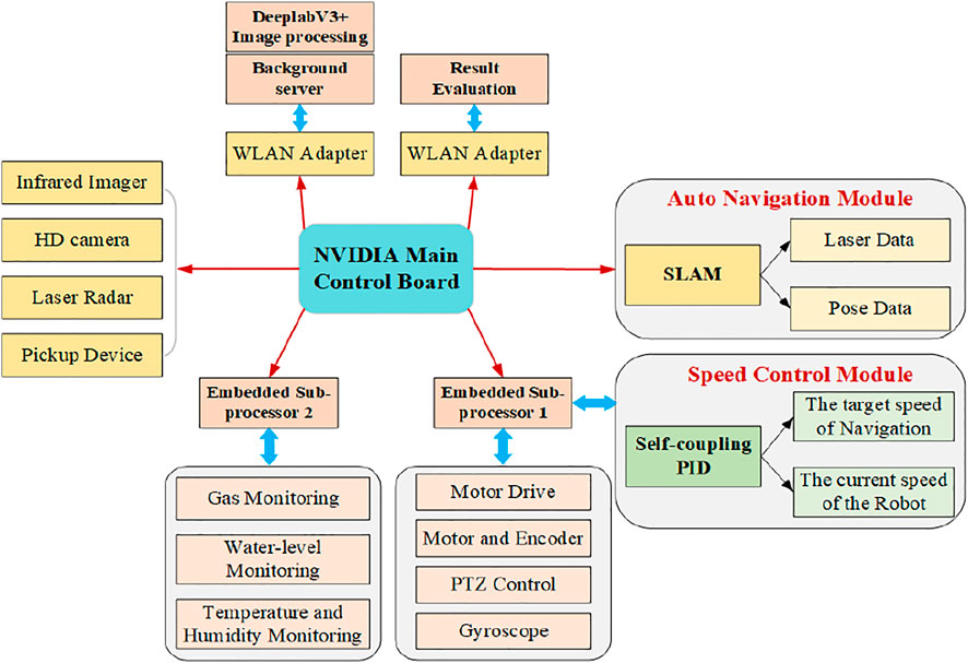
FIGURE 1. System structure of the intelligent inspection robot for the cable trench.
In addition, two embedded sub-processor modules are designed. One embedded sub-processor realizes the motion attitude control of the robot and the platform control so that the robot can complete the multidirectional and three-dimensional visual observation of the cable trench tunnel. Another embedded sub-processor module realizes the perception of the environmental information of the cable trench tunnel, which is connected with a variety of gas sensors, water level detection sensors, and temperature and humidity sensors.
Relevant sensor information was obtained, processed, and transmitted to the operation terminal and background server through WLAN for display and data evaluation. To ensure the stability and reliability of data transmission, a combination of dual wireless network cards and high-power base stations is adapted to transfer a large amount of data, strengthen the power of wireless transmission, and ensure the stability and reliability of communication.
The operation and maintenance of the underground cable trench require long-term supervision and inspection by staff, but some human negligence will inevitably lead to accidents. To avoid this situation, this study designs an underground cable trench condition evaluation system based on edge intelligence, which mainly includes the following two steps:
The robot conducts patrol inspection in the underground cable trench through the autonomous navigation system and sends its position and sensor data to the background server in real time. The autonomous navigation algorithm consists of mapping, location, and path planning, and the involved data are huge and with high real-time ability, which could hardly be processed by an upper computer through wireless communication. Without waiting for the response of the computing center through the network, edge intelligence can process data locally, which decreases system delay, promotes the response speed significantly, and is suitable for the application of this scenario.
According to the transmitted position data, the designated robot will evaluate the overall system inside the cable trench every 50 m to realize the distributed management inside the cable trench, and according to the relevant instructions automatically generated by the evaluation results, the drainage system, exhaust system, fire extinguishing system, and other prevention systems located in the corresponding sections of the underground cable trench are started intelligently to realize the edge intelligent management of the underground cable trench.
Autonomous navigation technology of the inspection robot is mainly designed from three aspects: “Where am I?”, “Where am I going?”, and “How do I get there?”. This study solves the abovementioned three problems through the following two parts: the first part is the SLAM system for real-time analysis and the second part is path planning.
To realize autonomous positioning and map construction, the inspection robot in this study adopts the open-source slam library cartographer SLAM (Hess et al., 2016) (released by Google in 2016). The hierarchical optimization idea is adopted in this algorithm. The front end uses the unscented Kalman filter (UKF) algorithm to fuse multi-source data (lidar, IMU, and encoder) for pose estimation, and a sub-map is constructed. The back end takes the sub-map as the basic unit to construct the loop constraint problem and proposes a branch and bound algorithm to speed up the construction of sub-map constraints. It overcomes the drawback that the filtering SLAM algorithm relies too much on the odometer and cannot build a large-scale map, and it is suitable for the scene such as the ground and the wall environment of the underground cable trench.
It is mainly composed of global paths and local paths. This study adopts the A * algorithm (Ammar et al., 2016) on the global path. With the combination of heuristic search and the breadth-first algorithm, the A* algorithm is the most effective direct search algorithm to solve the optimal path in a static environment.
The three improvements mentioned before are performed and compared with the original A* algorithm. Figure 2 illustrates the difference between them. The red path in Figure 2 is obtained by the original A* algorithm, and the yellow area is its search range. Meanwhile, the blue path is the result of the proposed improved A* algorithm, and the green area is its search range.
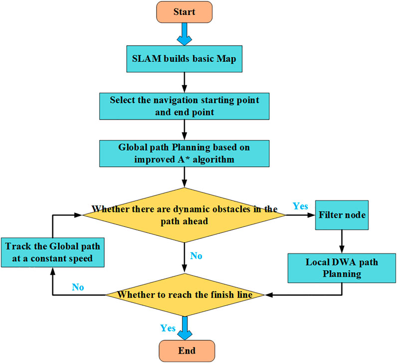
FIGURE 2. Multiple trajectory generation graphs of the robot.
Local path planning used in this study is the dynamic window method (Fox et al., 1997; Seder and Petrovic, 2007; Doopalam, 2015), which is based on the forward kinematics solution of the robot. The path was simulated from the simulating space of forwarding velocity and angular velocity, and the position control of the robot was converted into a speed control. The optimal local path is obtained by scoring the trajectory to be evaluated.
The traditional global path planning and local path planning fusion scheme is shown in the document (Cao et al., 2020; Lao et al., 2021) and the ROS official navigation fusion scheme (Move base in ROS, 2021). However, in an underground cable trench, the use of traditional methods to merge the global path and the local path will cause the following problems.
(1) The dynamic window method is used too many times in the actual experiment which increases the inspection time.
(2) Due to the narrow space of the underground cable trench, the local planning will cause the robot to produce more inflection points during the forward process.
(3) If dynamic obstacles appear in the global path, the dynamic window method will linger around the obstacles appearing in the global path for a period, which will seriously affect the work efficiency of the robot.
This study proposes a fusion algorithm of global path planning and local path planning for the underground cable trench environment. The flow chart of the fusion algorithm is illustrated in Figure 2. If the current trajectory is feasible, the robot moves along with the current trajectory at a constant speed and keeps detecting the surrounding environment in real time. The measured fusion laser data are used as the center to define a circle and the length of the robot body as the radius to expand and linger around an obstacle if a new obstacle is detected in the global path planning. DWA local planning will begin, and all global path nodes included in the obstacle are discarded. The global path nodes that are out of the obstacle and close to the navigation endpoint will be used as the endpoint of DWA local planning. Three evaluation functions are used to evaluate all the paths generated from the starting point to the endpoint, and each evaluation function is accumulated to set the trajectory with the lowest cost as the best trajectory.
The edge intelligent system of the underground cable trench is mainly analyzed and calculated by the edge computing device. First, a terminal level edge computing device is installed in the inspection robot to realize the autonomous navigation task of the robot in the internal environment of the underground cable trench. On this basis, the edge evaluation system is modeled. In this study, several fixed edge servers are installed in the internal environment of the underground cable trench. The edge server is uploaded to the cloud computing console, and the intelligent evaluation system for the underground cable trench edge is realized through the built cloud platform. The inspection robot transmits the collected sensor data to the nearest edge server during driving, realizes the distributed management of the cable trench, and visually manages the internal environment and evaluation results of the underground cable trench. Through the visual interface, the evaluation results and real-time internal environment of all sections can be displayed to the staff. The corresponding solutions are automatically generated according to the evaluation results to form a cloud edge and a collaborative underground cable trench edge intelligent evaluation system.
The network architecture of the underground cable trench edge intelligent evaluation system is shown in Figure 4, which is mainly divided into four layers:
(1) The sensing layer mainly completes the state perception of the inspection robot to the internal environment of the cable trench. The sensing layer includes the terminal level autonomous navigation system and the edge level cable trench evaluation system. It is mounted on the machine Jetson Nano and carries out the terminal level autonomous navigation system through the collected lidar data. Then, the image, gas, and robot pose data are uploaded to the nearest edge server and uploaded to the cloud.
(2) The network layer mainly uses a high-power base station and power wireless private network to complete the safe and reliable transmission of data.
(3) The platform layer is mainly based on the Internet of things management platform, which systematically evaluates the underground cable trench based on multi-sensor data and manages the corresponding drainage, exhaust, and other systems of the underground cable trench.
(4) The application layer develops the upper computer based on the tablet computer, and the staff can complete the real-time monitoring of the internal environment of the underground cable trench and the independent inspection route management through the upper computer.
To achieve a comprehensive assessment of the underground cable trench condition, the following information is obtained during inspection: infrared thermal imaging images, visible-light images, depth images, angular velocity, linear acceleration output by IMU, map from lidar, temperature, humidity information of the internal environment, and water level. Based on this information, an underground cable trench condition evaluation method is proposed. It mainly consists of three aspects:
(1) Air quality assessment in the cable trench based on the data set fusion method of sulfur dioxide, ozone, carbon dioxide, carbon monoxide, and other harmful gases.
(2) Internal structure evaluation of the cable trench based on a depth camera and IMU.
(3) Hazard assessment of ponding in the cable trench based on a visible camera, IMU, encoder, and water level sensor.
The accumulation of methane, hydrogen sulfide gas, carbon monoxide, and other harmful combustible gases produced by microbial decomposition of some animals and plants during power transmission is the main cause of fire and explosion in the cable trench. The air quality assessment method based on the fusion of gray clustering and extension neural networks (Wang and Zhang, 2021) is adopted in this study. Representative air pollutants are selected according to the gray correlation degree, and an extension neural network is constructed to evaluate the air quality. The steps of constructing the air quality assessment model are as follows:
(1) Seven detection gas data of CO2, TVOC, CH4, NH4, O3, HS, and CO are extracted and normalized, and the correlation coefficient ε_ab is calculated between different air pollutants. The value range of the absolute correlation coefficient ε_ab is distributed in the interval of [0,1]. Generally, when the absolute correlation value is greater than 0.5, there is a positive correlation between the corresponding air pollutants. To cluster air pollutants, the first thing is to determine the value of the critical value r of the correlation degree. The value range of r is generally 0.5 < r < 1. When ε_ab ≥ r, pollutants a and b are regarded as the same type.
(2) In the air quality monitoring database of the underground cable trench cloud platform, there are five air quality levels: excellent, good, light pollution, medium pollution, and heavy pollution. For each level machine, 100 measurement data at different times and different measurement positions are selected to calculate the correlation coefficient ε_ab between different pollutants. According to relevant experience, the critical value of the correlation degree r = 0.7 is selected here. If the accuracy of the final air quality assessment result does not meet the requirements, it will be adjusted. The seven pollutants are divided into the following three categories according to their correlation: (CO2 and TVOC), (CH4, NH4, O3, and HS), and (CO), which are selected as the indicator to represent each category.
(3) A matter-element model
(4) The air quality assessment results can be calculated by inputting the detected air pollutants into the trained air quality assessment model. The overall process of the cable trench air assessment is shown in Figure 3.
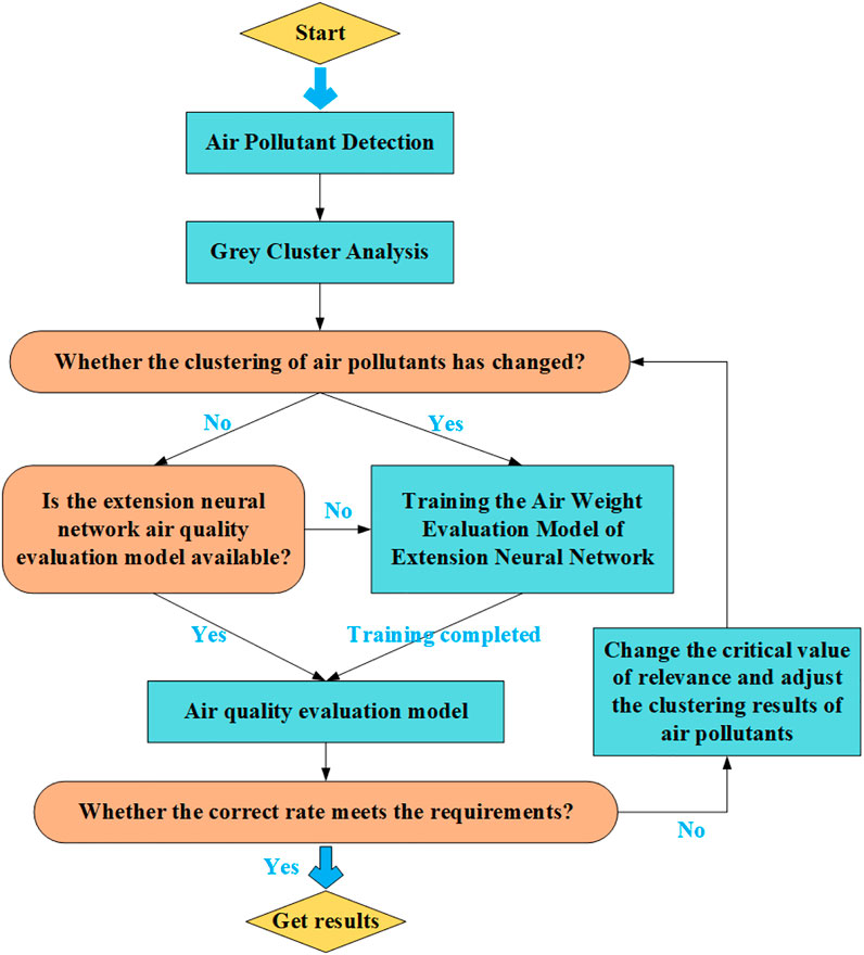
FIGURE 3. Overall process of cable trench air assessment.
Due to defects in the design and layout of the cable trench, cable suspensions and irregular cable stacks often exist in the interior, and construction materials and rubble cumulate on the bottom of the cable trench (as shown in Figure 4), which make the maintenance of the cable trench more difficult. Furthermore, the irregular layout of the cable stimulates additional eddy current on the metal sheath, leading to the operating temperature rise of the cable and local insulation aging, which affect the safe operation of the cable. Based on the information from the depth camera and IMU, the internal structure of the cable trench is evaluated from the capacity assessment of the trench and the pavement smoothness in this study.
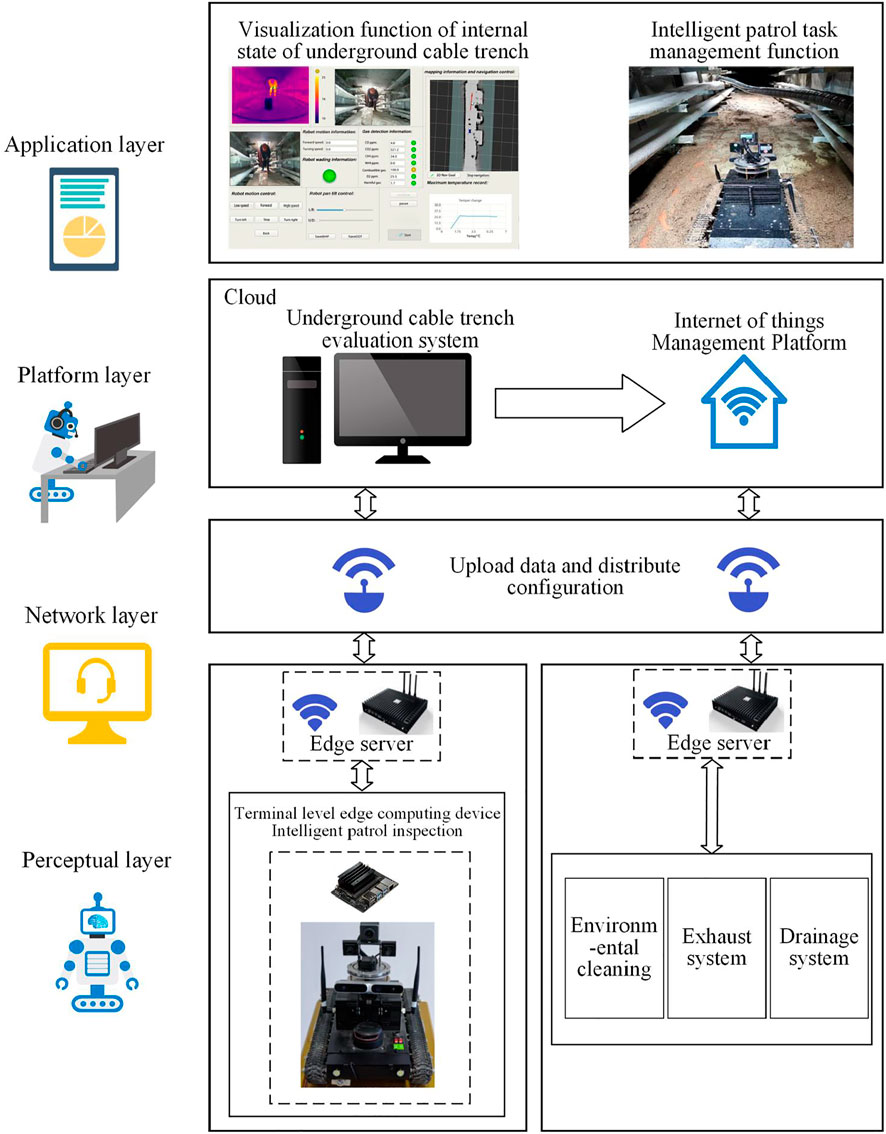
FIGURE 4. Intelligent overall block diagram of the underground cable trench edge.
To measure the pavement smoothness during the inspection, the IMU median integral is adopted to calculate the attitude of the robot on the ground during the inspection. The robot carrier coordinate system B is consistent with the IMU coordinate system, the world coordinate system is W, the origin is the carrier center during the system initialization, and the Z-axis direction is aligned with the gravity direction in the world coordinate system. The attitude calculation based on the linear acceleration from IMU is as follows:
where

FIGURE 5. Schematic diagram of robot and world coordinate systems.
The unevenness of the road is mainly affected by the change rate of the pitch angle and the roll angle of the robot in the inspection process. Therefore, the variance of the pitch angle and the roll angle of the robot in the inspection process is calculated every 50 m (e.g., Eqs 5, 6), where
To evaluate the traffic capacity of the cable trench, a depth camera with an effective range of 20 m is placed in front of the robot to obtain 3D point cloud information. The underground cable trench in the world coordinates is a map to 3D point cloud and forms the point set
All points in the set

FIGURE 6. Flow chart of cable trench trafficability evaluation.
By performing abovementioned steps, the variance of the pitch angle and roll angle of the robot and the traffic capacity of the cable are obtained every 20 m. The sum of the variance of the pitch angle and roll angle is normalized and defined as the pavement flatness coefficient. According to the investigation results of the actual condition of the cable trench and expert analysis, the classification of the safety grade of the cable trench structure evaluation is shown in Table 1 below.
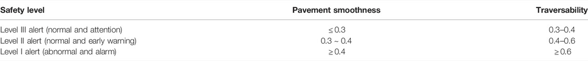
TABLE 1. Safety classification of the internal structure of the cable trench.
The underground cable trench easily accumulates water which makes internal moisture too high and leads to the oxidation and fracture of the metal cross arms on both sides of the cable trench. Meanwhile, heat dissipation of the cable is pretty slow in this situation, which accelerates the thermal aging of cable insulation. Therefore, water accumulation is an important factor to evaluate the condition of the cable trench. In this study, a visible-light camera, water level sensor, IMU, and encoder are integrated to evaluate the water accumulation in the cable trench.
Considering the situation of deep ponding, a water level sensor is placed under the robot. Water hazard in the cable trench is divided into two cases. When the water level sensor under the robot is triggered, the water hazard is evaluated by the volume of ponding; otherwise, the water hazard is evaluated by the surface area of ponding. For the first case, when the robot passes through the ponding, the water level sensor is triggered, and the current travel speed of the robot
When the ponding is too shallow to trigger the water level sensor, the ponding area is obtained from the image data taken by the visible camera. The DeepLabV3+ neural network framework (Chen et al., 2018) is used to construct the ponding segmentation model, and MobileNetV3 (Howard et al., 2019) is selected as the backbone network for preliminary feature extraction, which not only ensures the lightweight of the network but also has good performance. The context information of the image is extracted from multiple scales, combined with the output of the low-level feature by the decoding module and the backbone network, which could significantly improve the edge detection accuracy of ponding. The visible light DeepLabV3+ identification ponding process is shown in Figure 7.
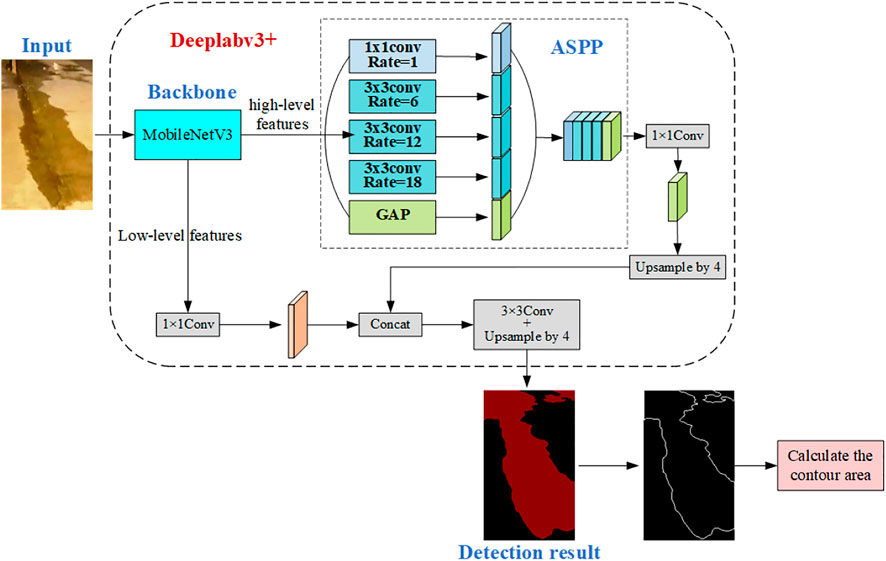
FIGURE 7. Ponding area identification process.
The field test is carried out in the cable trench environment, as shown in Figure 8. Jetson Nano is adopted as the core processor and is loaded with Ubuntu 18.04 and ROS. It collects data from lidar and depth cameras to build maps and navigate the route. Two microcontrollers (STM32F103) are selected as the chip, one of which is used to receive commands from the processor and the upper computer and control the movement of the robot. The other one is equipped with methane, ozone, combustible gas, and other harmful gas detection sensors, as well as nine-axis IMU sensors and a water level sensor.
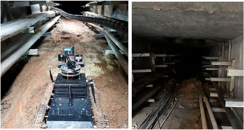
FIGURE 8. Hanging cable (left); accumulation of rubble and building materials (right).
To verify the path fusion algorithm, a man-made dynamic obstacle is set in the field test (as shown in the red box of Figure 9). The path obtained by the traditional path fusion algorithm is shown in the blue line segment in Figure 9. Due to the narrow space of the cable trench and the relatively small distance between the obstacle and wall, the traditional global path planning method generates unnecessary inflection points on the path. Furthermore, when a dynamic obstacle appears on the global path, the robot will wander around the obstacle to make redundant judgments, which affects the inspection efficiency. The red line segment in Figure 9 is the path obtained by the proposed fusion method. The robot retains the smoothness of the global path before encountering dynamic obstacles during the on-site inspection. When the dynamic obstacles appear on the global path, the global path nodes contained in the dynamic obstacles are automatically filtered, and the path avoiding the dynamic obstacles is smoother and with less judgment and higher efficiency.
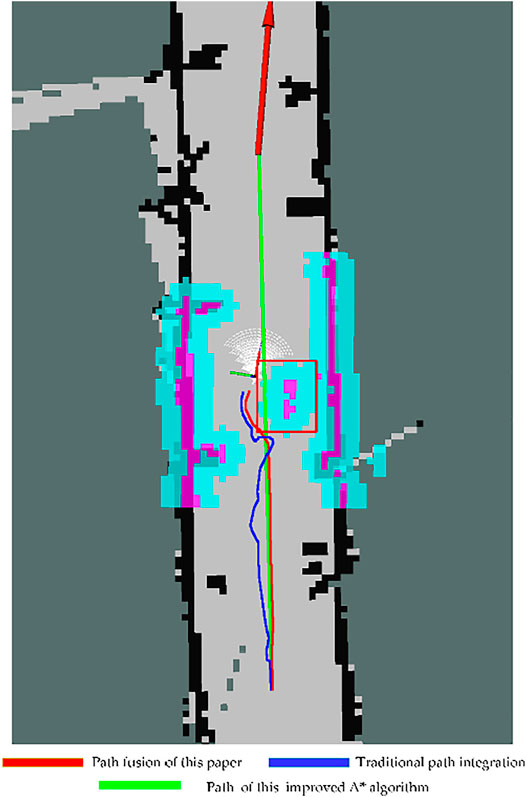
FIGURE 9. Environmental mapping and path planning of the cable trench.
To verify the effectiveness and operability further, repetitive on-site experiments were carried out using the traditional fusion path algorithm and the proposed method, respectively, with different starting points and target points. Reducing the random error caused by the operation, three cable trenches with different lengths are chosen and inspected five times each, and the average length of route and time consumption is calculated as the final results (as shown in Table 2). Compared with the traditional fusion path algorithm, the inspection speed of the improved fusion path algorithm proposed in this study increases by 21%, and the total path is shorter. The on-site experiments verified the advantages of the proposed path planning method.
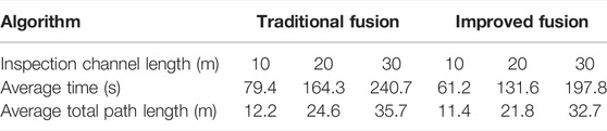
TABLE 2. Average value of traditional and improved fusion path algorithms.
The inspection robot completes the task of automatic navigation through the edge computing device mounted inside the fuselage. During movement, the image, gas, IMU, encoder, and robot position data are transmitted in real time to the nearest edge server, which is transmitted to the cloud computing platform through wireless transmission. In the cloud computing platform, combined with the position of the inspection robot in the underground cable trench, the underground cable trench is managed in a distributed manner. The data of every 50-m section of the underground cable trench are processed and analyzed in real time through the evaluation algorithm proposed in this study, and the corresponding solutions are given. The cloud platform is wirelessly transmitted to the edge server of the corresponding section through the Internet of things platform. Thus, the corresponding drainage system and exhaust system can be started, and the staff can monitor the real-time environment of the underground cable trench through the flat plate. As shown in Figure 10, the upper computer shows the information and status of the robot working in the cable trench.
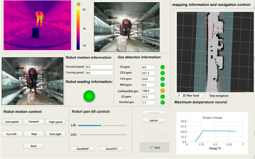
FIGURE 10. Monitoring interface of the upper computer in the cable trench.
During the field test, the proposed robot can build a map in an unfamiliar environment with a positional error of less than 8 cm. Global path planning is designed based on the improved A* algorithm, and dynamic path planning is designed based on DWM. The two algorithms are integrated to navigate the route. The path is accurately tracked to avoid obstacles, and the average speed is greater than 0.4 m/s. As shown in the upper computer, the inspection robot has an infrared thermal imaging camera, high-definition camera, and depth camera to monitor the underground cable trench and can detect the concentration of seven kinds of harmful gases. Applying the underground cable trench condition assessment method based on edge intelligence presented in this study, the internal environment of the cable trench is inspected in real time, the overall evaluation of the section is carried out every 50 m, and the overall healthy environment and countermeasures are fed back to the staff. The evaluation results are illustrated in Table 3.
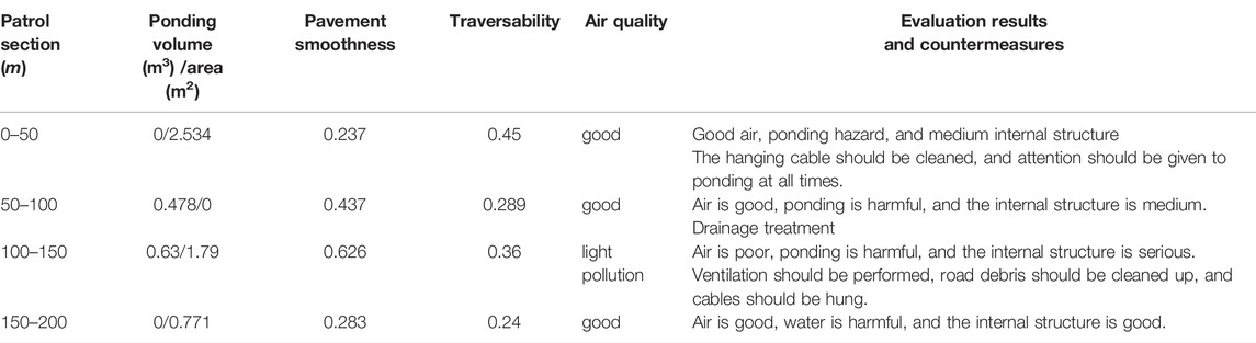
TABLE 3. Assessment results and countermeasures.
The proposed condition assessment method based on the inspected robot makes a distributed evaluation for the overall environment of the underground cable trench without manual interference. It provides a real-time condition of the cable trench from point to point and end to end. The corresponding countermeasures are given, which greatly improves the internal security of the cable trench. The feasibility and practicability of our method are verified in the field tests.
Substituting for the staff to carry out status monitoring and condition assessment in the high-risk environment of the underground cable trench, an automatic inspection robot system is proposed according to this environment, and a condition assessment method is designed based on the information collected by the robot. The designed robot has a good movement ability in the underground cable trench and can execute automatic navigation.
During the operation of the inspection robot designed in this study, all the data taken by the road section are uploaded to the background server every 50 m. Through a multi-source sensor fusion method proposed in this study, the air quality, internal structure, and ponding hazards of the underground cable trench in this road section are evaluated. At the same time, to apply the results of edge intelligent evaluation of the underground cable trench, the drainage system, exhaust system, fire extinguishing system, and alarm system of the road section can be started according to these results.
Applying the robot to an underground cable trench instead of manual inspection can reduce the inspection intensity and difficulty of staff. The stability and reliability of cable maintenance are improved significantly, and economic and social benefits are promoted a lot. The industrial application of the proposed technology in the future relies on two aspects. One is the promotion of reliability and obstacle-surmounting ability of the inspection robot platform. More field tests for the improvement of the practicality of the condition assessment method are the other aspects (Lao et al., 2021).
The raw data supporting the conclusions of this article will be made available by the authors, without undue reservation.
ZJ, ZL and SF contributed to the concept and design of the study. ZJ and ZL realized the robot. YT performed the field tests. ZJ wrote the first draft of the manuscript. YT and ZL wrote sections of the manuscript. All authors contributed to manuscript revision, read, and approved the submitted version.
This work was supported in part by the Research Foundation of Education Bureau of Hunan Province, China (Grant Nos. 19B016 and 20A028), in part by the Open Research Foundation of Hunan Province Key Laboratory of Electric Power Robot, China (Grant Nos. PROF1905 and PROF1901), and in part by the Changsha Municipal Natural Science Foundation, (Grant No. kq2014105).
The authors declare that the research was conducted in the absence of any commercial or financial relationships that could be construed as a potential conflict of interest.
All claims expressed in this article are solely those of the authors and do not necessarily represent those of their affiliated organizations, or those of the publisher, the editors, and the reviewers. Any product that may be evaluated in this article, or claim that may be made by its manufacturer, is not guaranteed or endorsed by the publisher.
Ammar, A., Bennaceur, H., Châari, I., Koubâa, A., and Alajlan, M. (2016). Relaxed Dijkstra and A* with Linear Complexity for Robot Path Planning Problems in Large-Scale Grid Environments[J]. Methodologies Appl. 20, 4149–4171. doi:10.1007/s00500-015-1750-1
Cao, Y., Zhou, Y., and Zhang, Y. (2020). Obstacle Avoidance Path Planning of mobile Robot Based on Optimized A∗ and DWA Algorithm [J]. Machine tools and hydraulics 48 (24), 246–252. doi:10.3969/j.issn.1001-3881.2020.24.034
Chen, L. C., Zhu, Y., Papandreou, G., Schroff, F., and Adam, H. (2018). Encoder-Decoder with Atrous Separable Convolution for Semantic Image Segmentation[J]. Cham: Springer.
Commission of the European Communities (2003). Background Paper Undergrounding of Electricity Line in Europe[R]. Brussels: Commission of the European Communities.
Dey, S., and Mukherjee, A. (2016).Robotic SLAM: a Review from Fog Computing and Mobile Edge Computing Perspective[C], Proceeding of the the 13th International Conference. New York, NY: ACM.
Doopalam, T. (2015). Hybrid Motion Planning Method for Autonomous Robots Using Kinect-Based Sensor Fusion and Virtual Plane Approach in Dynamic Environments[J]. J. Sensors 2015 (5), 1–13. doi:10.1155/2015/471052
Fox, D., Burgard, W., and Thrun, S. (1997). The Dynamic Window Approach to Collision Avoidance. IEEE Robotics Automation Mag. 4 (1), 23–33. doi:10.1109/100.580977
Hepburn, D. M., Zhou, C., Song, X., Zhang, G., and Michel, M. (2016).Analysis of On-Line Power cable Signals[C], Proceeding of the International Conference on Condition Monitoring & Diagnosis, April 2008, Beijing, China. IEEE.
Hess, W., Kohler, D., Rapp, H., and Andor, D. (2016).Real-time Loop Closure in 2D LIDAR SLAM, Proceedings of the 2016 IEEE International Conference on Robotics and Automation (ICRA). Stockholm, Sweden: IEEE, 1271–1278. doi:10.1109/icra.2016.7487258
Howard, A., Sandler, M., Chu, G., Chen, L. C., Chen, B., Tan, M., et al. (2019). “Searching for Mobilenetv3,” in Proceedings of the IEEE International Conference on Computer Vision, 1314–1324. doi:10.1109/iccv.2019.00140
Jongen, R., Quak, B., Tenbohlen, S., and Gulski, E. (2012).New Developments in On-Site Testing of Long Lengths of (E)HV Power Cable[C], Proceeding of the International Conference on Condition Monitoring & Diagnosis, Sept. 2012, Bali, Indonesia. IEEE.
Lyall, J. S., Nourbakhsh, G., and Zhao, H. C., "Underground Power cable Environment On-Line Monitoring and Analysis," Proceeding of the 2000 Power Engineering Society Summer Meeting (Cat. No.00CH37134), 2000, July 2000. Seattle, WA, USA, 457–462. vol. 1, doi:10.1109/PESS.2000.867629
Kang, K. J., Lee, J. W., Lee, E. D., and Kim, M-D. (2018).Intelligent Autonomous Driving Condition Monitoring and Diagnosis Robot-System of Underground Electric Power Conduit Pipe[C], Proceeding of the 2018 Condition Monitoring and Diagnosis (CMD), Sept. 2018, Perth, WA, Australia. IEEE, 1–5.
Lao, C., Peng, L., and Yu, F. (2021). Greenhouse Robot Path Planning Based on the Fusion of Improved A* and DWA Algorithm [J]. J. Agric. machinery 52 (01), 14–22. (in Chinese). doi:10.6041/j.issn.1000-1298.2021.01.002
Li, E., Zhou, Z., and Chen, X. (2018). Edge Intelligence: On-Demand Deep Learning Model Co-inference with Device-Edge Synergy[J].
Ling, Z., Tang, M., Zhang, K., fan, S., and Jia, Z. (2020). Design of cable Trench Inspection Robot System Based on Improved D * Lite Algorithm [J]. Comp. Meas. Control 28 (09), 187–190+201. (In Chinese). doi:10.16526/j.cnki.11-4762/tp.2020.09.037
Liu, K., and Yin, Y. (2007). Technical and Economic Analysis of Overhead Lines and Underground Cables in Urban Power Grid [J]. Guangdong electric power 20 (05), 25–27. (in Chinese). doi:10.3969/j.issn.1007-290X.2007.05.007
Lu, S., Zhang, Y., and Su, J. (2017). Mobile Robot for Power Substation Inspection: a Survey. Ieee/caa J. Autom. Sinica 4 (4), 830–847. doi:10.1109/JAS.2017.7510364
Move base in Ros Move Base in ROS. Available online: http://wiki.ros.org/move_base/(accessed on 3 20, 2021).
Pal, D., Meyur, R., Menon, S., Reddy, M. J. B., and Mohanta, D. K. (2017). Real-Time Condition Monitoring of Substation Equipment Using Thermal Cameras[J]. Iet Generation Transm. Distribution 12 (4), 895–902. doi:10.1049/iet-gtd.2017.0096
Patel, P., Ali, M. I., and Sheth, A. (2017). On Using the Intelligent Edge for IoT Analytics[J]. IEEE Intell. Syst. 32, 64–69. doi:10.1109/mis.2017.3711653
Premsankar, G., Di Francesco, M., and Taleb, T. (2018). Edge Computing for the Internet of Things: A Case Study [J]. IEEE Internet Things J. 5, 1275–1284. doi:10.1109/jiot.2018.2805263
Seder, M., and Petrovic, I. (2007).Dynamic Window Based Approach to mobile Robot Motion Control in the Presence of Moving Obstacles [C], Proceedings of the IEEE International Conference on Robotics and Automation, April 2007, Rome, Italy. IEEE.
Siddiqui, B. A., Pakonen, P., and Verho, P. (2017). Novel Inductive Sensor Solutions for On-Line Partial Discharge and Power Quality Monitoring. IEEE Trans. Dielect. Electr. Insul. 24 (1), 209–216. doi:10.1109/tdei.2016.005908
Song, W. (2015). Research on Wireless Sensing and Safety Status Evaluation of Underground cable Channel [D]. Kunming, China: Kunming University of Technology. (In Chinese).
Sun, T., Ye, L., Xie, J., Zhang, J., Fan, M., and Fan, H. (2021). Research and Application of Substation cable Trench Inspection Robot Communication System. J. Phys. Conf. Ser. 2031 (1), 012025. doi:10.1088/1742-6596/2031/1/012025
Wang, B., Guo, R., Li, B., Han, L., Sun, Y., and Wang, M. (2012). SmartGuard: an Autonomous Robotic System for Inspecting Substation Equipment. J. Field Robotics 29 (1), 123–137. doi:10.1002/rob.20423
Wang, T., and Zhang, X. (2021). Research on Air Quality Evaluation Method of Civil Air Defense Engineering Based on Improved Extension Neural Network [J]. Mech. Des. manufacturing 2021 (01), 286–291. (in Chinese). doi:10.19356/j.cnki.1001-3997.2021.01.066
Wu, Y-H., and Zhang, J. S. (2014). System of Fault Diagnosis and Operation Monitoring for Low-Voltage Distribution Equipment[J]. J. Mech. Electr. Eng. 31, 795–799. doi:10.3969/j.issn.1001-4551.2014.06.026
Keywords: underground cable trench, robot system, multi-sensor data fusion, condition monitoring, condition assessment
Citation: Jia Z, Tian Y, Liu Z and Fan S (2022) Condition Assessment of the Cable Trench Based on an Intelligent Inspection Robot. Front. Energy Res. 10:860461. doi: 10.3389/fenrg.2022.860461
Received: 23 January 2022; Accepted: 22 March 2022;
Published: 25 April 2022.
Edited by:
Yan Xu, Nanyang Technological University, SingaporeReviewed by:
Elmer Magsino, De La Salle University, PhilippinesCopyright © 2022 Jia, Tian, Liu and Fan. This is an open-access article distributed under the terms of the Creative Commons Attribution License (CC BY). The use, distribution or reproduction in other forums is permitted, provided the original author(s) and the copyright owner(s) are credited and that the original publication in this journal is cited, in accordance with accepted academic practice. No use, distribution or reproduction is permitted which does not comply with these terms.
*Correspondence: Zhiwei Jia, amlheWVnZUBjc3VzdC5lZHUuY24=
Disclaimer: All claims expressed in this article are solely those of the authors and do not necessarily represent those of their affiliated organizations, or those of the publisher, the editors and the reviewers. Any product that may be evaluated in this article or claim that may be made by its manufacturer is not guaranteed or endorsed by the publisher.
Research integrity at Frontiers
Learn more about the work of our research integrity team to safeguard the quality of each article we publish.