 Fangwei Xie1,2*
 Xiuwei Shi
95% of researchers rate our articles as excellent or good
Learn more about the work of our research integrity team to safeguard the quality of each article we publish.
Find out more
ORIGINAL RESEARCH article
Front. Energy Res. , 12 April 2022
Sec. Process and Energy Systems Engineering
Volume 10 - 2022 | https://doi.org/10.3389/fenrg.2022.854529
This article is part of the Research Topic Design, Simulation and Optimization of Hydraulic Machinery View all 25 articles
Valve-controlled damping adjustable damper has the characteristics of simple structure and adjustable damping, and it has always been a hot research topic. This paper establishes a mathematical model of damping characteristics of the valve-controlled damping adjustable damper and designs the experiment of the damping characteristics of the compression stroke and the recovery stroke. Through simulation and experiment, the accuracy of the mathematical model is verified, and the damping contribution rate of different key parameters under different excitation speeds is analyzed. The results show that the mathematical model of the damping characteristics can well describe the working state of the damper. The damping contribution rate of key parameters under different excitation speeds is obtained. The damping contribution of the constant through-hole diameter decreases gradually after the valve is opened for the first time. With the increase of the excitation speed, the valve plate equivalent thickness and the valve plate maximum limit clearance of the check valve gradually play a major role in the damping contribution rate. The research results can screen out the key parameters, improve the development efficiency of the damper, and provide guidance for the damper design and optimization.
As a key component of a semi-active suspension system, the valve-controlled damper is always a research hotspot (Wang, 2016; Yang et al., 2019; Cao, 2020). The damper belongs to the damping multi-state switching damper. Different damping oil circuits are designed by using multiple superimposed valve groups, the oil circuit is switched by an electromagnetic start-stop valve to realize damping adjustment, the adjustable damping damper controlled by the valve has great stability and good promotion perspective. Researchers at home and abroad have studied damper for more than one hundred years and achieved a series of results (Lindler et al., 2000; Liu et al., 2019).
Maemor et al. (2003) proposed an optimization method for the semi-active damper and optimized the area of the compensation hole of the damper with the minimum vertical acceleration as the optimization objective. The results show that the optimized damper can better cope with the change of aircraft mass than the original damper. Causemann (2003) developed a continuously variable damper. The external pilot relief valve can continuously adjust the damping force of the damper in real-time by collecting road spectrum and body posture information. Farjoud et al. (2012) established a nonlinear model of the damper, studied the influence of the parameters of the superposition valve on the damping characteristics, and verified the correctness of the mathematical model through experiments. Luczko and Ferdek (2019) designed a damping adjustable hydraulic damper with an additional inner cylinder. The purpose of changing the damping characteristics according to the road conditions is realized by selecting the appropriate structural parameters.
Zhou and Ren (2009) studied the optimal damping matching of automobile suspension and optimized the thickness of the throttle valve plate of the damper by using the design method of optimal curve fitting. Chen et al. (2013) designed a valve-controlled multi-state switching damper and analyzed the relationship between the damping force of the damper and the stroke and frequency. The experimental results show that the mathematical model has high accuracy. Xuan (2016) designed a four gear valve-controlled adjustable damper, deduced the mathematical model of damping force in the working process, and developed a prototype of the damper. The experimental results show that the valve-controlled adjustable damper can meet the application requirements. Ding et al. (2018) designed an ADS (Adjuster Damping Control) damper, established mathematical models of damping characteristics in different gears, and the influence of geometric parameters of ADS valve damping characteristics are studied. Xie et al. (2018) used Matlab to deduce the analytic expressions of deflection deformation of the single valve plate and the superimposed valve plate and analyzed the influence of geometric parameters of annular valve plate on the deflection of the valve plate. The research has a certain guiding significance for parametric modeling and the optimal design of the damper. Wang et al. (2018) took the maximum adjustment range of MRF (Magnetorheological Fluid) damper as the goal and optimized the effective length of working cylinder, piston rod diameter, and piston diameter by using the Matlab optimization toolbox. The results show that the method is accurate and reliable. Ma (2018) established an RSM (Response Surface Methodology) model of multi-point force damper, selected ten design variables, optimized the design with the indicator characteristics under multiple speed conditions proposed by the cooperative enterprise, which guided the similar engineering. Zhang et al. (2019) established a fluid-structure coupling model of the damper with ADINA, analyzed the influence of different elastic modulus and viscosity on the damping stiffness. Huang et al. (2020) established a simulation model of electro-hydraulic pneumatic coupling damper by AMESim, studied the indicator characteristics and velocity characteristics under different current and external excitation conditions, in addition, explored the influence of different structural parameters of the damper damping characteristics.
At present, many mathematicians have carried out a lot of research on the influence of different structural parameters on the damping characteristics of the damper, and have achieved some results, but most of these researches focus on qualitative analysis and the influence weight of each parameter is not given. To improve the performance of the damper, researchers use different optimization methods to optimize the design of the single tube, double tube, and magnetorheological fluid dampers (Fu, 2016). However, there are few studies on the optimization design of the valve-controlled adjustable damper. At present, the development of the damper still has to carry out the cycle “design, experimentation, evaluation, improvement”. Designers spend a lot of time and energy on repetitive work. At the same time, most adjustment of parameters still depends on experience, which has the disadvantages of low development efficiency and long cycle. With the wide application of the valve-controlled adjustable damper, the demand for the optimal design of this type of damper is more and more intense.
This paper establishes the mathematical model of damping characteristics of the valve-controlled damping adjustable damper and designs the experiment of damping characteristics of the compression stroke and the recovery stroke. Through simulation and experiment, the accuracy of the mathematical model is verified, and the damping contribution rate of key parameters of the valve-controlled damping adjustable damper under different excitation speeds is analyzed. The research results can screen out the key parameters, improve the development efficiency of the damper, and provide guidance for the damper design and optimization.
Compared with the structure of the double tube damper, the valve-controlled damping adjustable damper adds a damping control valve on the outside, and the rest of the overall structure is similar to that of the double tube damper, Figures 1–3 show the structural diagram of the damping control valve and check valve, respectively.
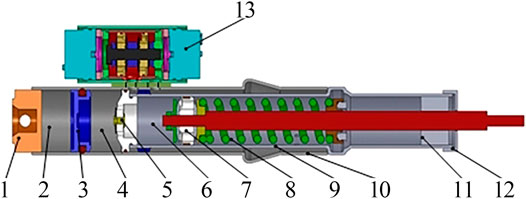
FIGURE 1. Structure of the valve-controlled damping adjustable damper. Note: 1. Mounting Base; 2. Nitrogen cavity; 3. Floating Piston; 4. Oil storage cavity; 5. Bottom Valve; 6. Compression Cavity; 7. Piston Valve; 8. Recovery Cavity; 9. Inner Cylinder; 10. Outer Cylinder; 11. Guide; 12. End Cap; 13. Damping Control Valve.
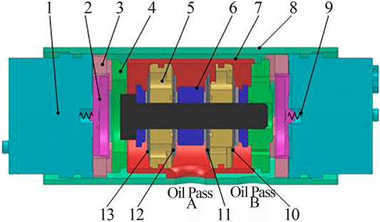
FIGURE 2. Structure of the damping control valve. Note: 1. Electromagnet; 2. Flapper valve spool; 3. Flapper valve body; 4. Transparent Cover; 5. Check valve; 6. Locate ring; 7. Inner cylinder; 8. Outer cylinder; 9. Reset spring; 10. Check Valve “d”; 11. Check Valve “c”; 12. Check Valve “b”; 13. Check Valve “a”.
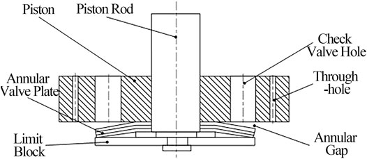
FIGURE 3. Structure of the check valve.
The valve-controlled adjustable damper consists of two parts: the main damper and the damping control valve. The main damper adopts the double tube structure, which is used as the oil channel to guide the oil in the recovery cavity and the compression cavity to the damping control valve. The piston valve of the damper reciprocates in the inner cylinder. The upper end of the inner cylinder realizes the movement guide and seal functions of the piston rod. The lower part of the inner cylinder has a bottom valve, and the lower part of the outer cylinder also has a floating piston. The floating piston can move in the lower part of the outer cylinder, and the mounting base is installed in the lower part of the outer cylinder, which is mainly used to connect with the outside.
The floating piston divides the bottom part of the outer cylinder into an oil storage cavity and nitrogen cavity. The bottom valve serves as the oil channel between the compression cavity and the oil storage cavity. The upper part of the inner cylinder has an oil hole, which can lead the oil in the recovery cavity into the clearance between the inner and outer cylinders. There are also two oil holes near the bottom valve of the outer cylinder. One oil hole penetrates the inner cylinder and is connected with the compression cavity, and the other oil hole is connected with the recovery cavity through the gap between the inner and outer cylinders. The damping control valve installed on the outer cylinder connects two oil holes, through the adjustment of the damping control valve, different damping forces are produced.
Figure 4 shows the working principle of the valve-controlled adjustable damper, and its working process can be divided into two parts: compression and recovery. The bottom valve consists of a compression valve and a compensation valve, the piston valve consists of a recovery valve and a flow valve. The oil flows between the damping control valve, the compression cavity, the recovery cavity, and the oil storage cavity through the piston valve and the bottom valve.
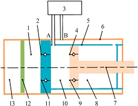
FIGURE 4. Working principle of valve-controlled damping adjustable damper. Note: 1. Oil storage cavity; 2. Compensate valve; 3. Damping control valve; 4. Flow valve; 5. Inner cylinder; 6. Outer cylinder; 7. Piston rod; 8. Recovery cavity; 9. Recovery valve; 10. Compression cavity; 11. Compression valve; 12. Float piston; 13. Nitrogen cavity.
During the compression stroke, the piston moves towards the bottom valve and the oil pressure in the compression cavity increases. There are three ways for the oil to flow from the compression cavity to the recovery cavity: the first one flows through the damping control valve; The second one flows through the flow valve; The third one flows through the compression valve. The oil in the oil storage cavity increases and the floating piston moves downward. The recovery stroke is similar to the compression stroke.
Figure 5 shows the working principle of the damping control valve. The step regulation of damping is mainly through the damping control valve. “Y1” and “Y2” are solenoid valves. “a”, “b”, “c” and “d” are check valves. When the solenoid valve is powered on, the oil circuit is opened. The solenoid valve loses power and the oil circuit is closed. During the compression stroke, the oil flows in through port “A” and out through port “B”, and the recovery stroke is the opposite.
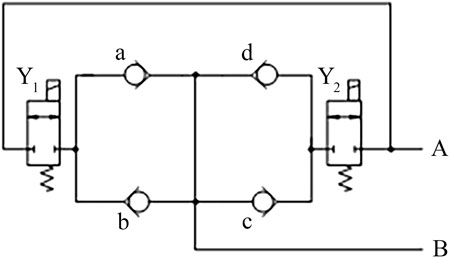
FIGURE 5. Working principle of damping control valve. Note: A: Oil pass “A”; B: Oil pass “B”.
Compression stroke: after the oil enters through port “A”, if both solenoid valve “Y1” and solenoid valve “Y2” are powered on, the oil can pass through check valve “a” and check valve “d”, and exit through port “B”; If the solenoid valve “Y1” is energized and the solenoid valve “Y2” is de-energized, the oil flows through the check valve “a” and out of the oil outlet “B”; If the solenoid valve “Y1” is de-energized and the solenoid valve “Y2” is energized, the oil flows through the check valve “d” and out of the oil outlet “B”.
Many factors affect the damping characteristics of the damper, such as the structural parameters of each valve system, the friction between the piston and the inner cylinder of the damper, the oil viscosity, the working temperature, and so on. Among them, the structural parameters of each valve system have a great influence on the damping characteristics, such as the constant through-hole diameter, the thickness of the valve plate, the limit clearance of the valve plate, and so on. To avoid the mathematical model being too complex and inconvenient for the subsequent simulation analysis and optimal design, it is necessary to simplify and assume the working process of the damper in the mathematical modeling. The simplification and assumption are as follows.
(a) The internal leakage of the damping control valve and the external leakage of the damper are ignored.
(b) It is assumed that the temperature of the damper is constant and the viscosity of the damper oil is constant.
(c) It is assumed that the damper oil is not compressible and the bubble phenomenon is not considered.
(d) The oil pressure of the recovery cavity and compression cavity is equal to the air pressure of the nitrogen cavity everywhere.
(e) It is assumed that there is no elastic deformation of the parts of the damper, such as the working cylinder and piston rod, except the annular valve plate.
The working principle of the damper compression stroke and recovery stroke is similar. This paper analyzes the compression stroke of the valve-controlled damping adjustable damper.
When the valve-controlled adjustable damper is on the compression stroke, the piston rod moves downward, the pressure of the compression cavity increases and the pressure of the recovery cavity decreases. Under the action of the piston, the oil in the damper flows from the compression cavity to the recovery cavity through the damping control valve. The pressure of the recovery cavity, compression cavity, and nitrogen cavity are P1, P2, and P3, respectively.
The piston separates the oil from the nitrogen gas. The pressure of the compression cavity and nitrogen cavity are equal. During the compression stroke, as the piston moves down, the pressure in the nitrogen cavity will also increase. According to the gas isothermal state equation:
Where P0 is the initial pressure of the nitrogen cavity (Pa); V0 is the initial volume of the nitrogen cavity (m3); xq is the nitrogen cavity piston displacement (m); r is the temperature index (r = 1.4).
In the compression stroke, the damping force is mainly caused by the pressure difference between the two ends of the piston and the friction between the piston and the working cavity:
Where Fc is the compression stroke damping force of the valve-controlled adjustable damper (N); Ad is the working cylinder area (m2); Ar is the piston rod area (m2); P1 is the oil pressure of the recovery cavity (Pa); P2 is the oil pressure of the compression cavity (Pa); Ff is the friction between the piston and the working cylinder during compression stroke (N); v is the piston movement speed (m/s); sng(v) is step function of v.
Where Ff is the friction force between the piston and the working cylinder during the compression stroke (N); Hr is the contact width between the piston and the working cylinder (m); Pn is the radial pressure on piston (Pa);
For the valve-controlled damper, the mechanical model of the piston valve system or the damper control valve system can simplify the mechanical model of the annular thin plate. The throttling gap of the ring valve divides three stages: before the first opening, after the first opening, and after the second opening. The size of the throttling gap, that is, the deflection of the valve plate is determined by the oil hydraulic pressure difference between the two ends of the valve system. The deflection of the valve plate is zero before the first opening, and the size of the throttling gap after the first opening is determined by the oil hydraulic pressure difference between the two ends of the valve system, the deflection of the annular valve plate is fixed after the second opening, which is equal to the maximum deflection after the first opening. Therefore, it is necessary to model the two states before and after opening the valve, respectively. The oil circuit diagram of the two cases is shown in Figure 6.
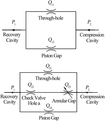
FIGURE 6. Oil circuit diagram of the compression stroke. Note: (A) Before opening the valve for the first time; (B) After opening the valve for the first time.
Figure 6A shows a schematic diagram of the oil circuit before opening the valve for the first time. When the vibration speed is small, the oil pressure is less than the valve plate pre-tightening force (Ma et al., 2013), that is, before the initial opening of the valve, the oil in the damper flows through the constant through-hole of the damping control valve and the piston gap.
The constant through-hole is a small hole with a thick wall:
Where ΔP21 is the pressure difference between the compression cavity and the recovery cavity (MPa); Ct is the flow coefficient of the constant through-hole; Nt is the number of the constant through-hole; At is the flow area of the constant through-hole (m2); ρ is the oil density (kg/m3).
The piston gap is an eccentric annular gap, and the flow through the piston gap can be expressed as:
Where ΔP21 is the pressure difference between the compression cavity and the recovery cavity (MPa); d is the inner diameter of the working cylinder (m); δ is the oil film thickness (m); e is the eccentricity; l is the gap length (m).
The constant through-hole is connected in parallel to the piston gap, and the total flow is:
Where vc1 is the piston movement speed of the compression stroke (m/s).
The pressure difference between the compression cavity and the recovery cavity can be obtained by Eq. 6. The final compression stroke is as follows:
Figure 6B shows the schematic diagram of the oil circuit after opening the valve for the first time. When the vibration speed increases, the oil pressure is greater than the valve plate pre-tightening force, that is, after the initial opening of the valve, the oil in the damper flows through the constant through-hole, throttle gap, and the piston gap, the throttle gap includes valve hole of check valve “a” and annular gap.
When the annular disc is open and the opening is fa, the throttle gap can be regarded as an annular plane gap, and the flow rate is expressed as:
Where fa is the maximum deflection of the annular disc of the check valve “a” (m); ΔP31 is the pressure difference at both ends of the check valve “a” (MPa); rc1 is the inner circle radius of the annular disc of the check valve “a” (m); rc2 is the outer circle radius of the annular disc of the check valve “a” (m).
Similar to Eq. 6, the throttle gap of the check valve “a” is connected in series with the hole of the check valve “a”, so the flow of the two is equal. The constant through-hole, throttling gap, and piston gap are parallel. The total flow after the opening of the valve can be obtained by adding the three flow rates. According to the above two groups of relationships, the total flow after the first opening of the valve is:
Where vc2 is the velocity of the piston movement after the initial valve opening of the compression stroke (m/s); Q21 is the flow of the through-hole (L/min); Q22 is the flow of the through-hole of check valve “a” (L/min); Q23 is the flow of the through the annular gap (L/min); Q24 is the flow of the through piston gap (L/min).
The flow calculation of “Q21” and “Q24” is similar to that of “Q11” and “Q12” before opening the valve for the first time. The pressure difference between the compression cavity and the recovery cavity can be obtained by Eq. 9. Finally, the damping force of the compressed stroke after opening the valve is:
The simulation analysis of damping characteristics of the valve-controlled adjustable damper can reduce the prototype experiment, evaluate the performance of the damper and improve the development efficiency.
Based on the mathematical model of the valve-controlled adjustable damper, the damping characteristic model of the valve-controlled adjustable damper is built by using Matlab software, and the damping characteristic is simulated and analyzed. Figure 7 shows the simulation flow chart of the adjustable damper.
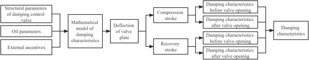
FIGURE 7. Simulation process of the adjustable damper.
The structural parameters and oil parameters of the damping control valve are internal parameters, and the external excitation is the external parameter. Combined with the mathematical model of damping characteristics, the damping characteristics of the compression stroke before and after opening the valve and the recovery stroke before and after opening the valve are solved, respectively, and the damping characteristic curve of the whole damper is drawn finally. According to the test requirements of damping characteristics of the damper, the external excitation signal is set as a sinusoidal signal with an amplitude of 50 mm.
The vibration speed of the damper are 0.05, 0.13, 0.26 0.39 and 0.52 m/s, the corresponding excitation frequencies are set at 0.16, 0.42, 0.83, 1.24 and 1.66 Hz, respectively. To improve the simulation efficiency, we choose the second gear of the damping valve as the simulated target, and Table 1 shows the main structural parameters of the damper under this target.
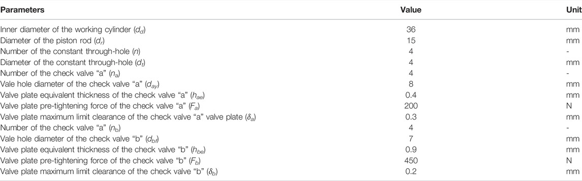
TABLE 1. Key structural parameters of the valve-controlled damping adjustable damper.
As shown in Figure 8, the indicated power characteristic curve of the valve-controlled adjustable damper can obtain by substituting the set parameters into the simulation program.
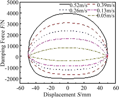
FIGURE 8. Indicator diagram of the damper.
As shown in Figure 8, when the excitation speed is 0.05, 0.13, 0.26, 0.39, and 0.52 m/s, the maximum compression damping force is 431 N, 909 N, 1268 N, 1690 N, and 2047 N, respectively, and the maximum recovery damping force is 780 N, 1638 N, 2348 N, 3099 N, and 3935 N, respectively. With the increase of the excitation speed, the damping force also increases and the maximum damping force appears in the stroke center of the damper. During the compression stroke, when the displacement is −20–20 mm, the damping force is basically unchanged. The damping force change rate gradually decreases from the maximum stroke to the stroke center, the curve is smooth, and the damping force is not distorted.
To ensure the accuracy and reliability of contribution rate analysis and damper parameter optimization results, it is necessary to verify the accuracy of the mathematical model of damping characteristics. Therefore, an experimental study on the valve-controlled adjustable damper is carried out.
Figure 9 shows a test bench for the valve-controlled adjustable damper. The test bench mainly consists of three parts: mechanical system, hydraulic system, and measurement and control system. The mechanical part is mainly composed of the bench and damper fixtures. The hydraulic part mainly includes a hydraulic pump station, electro-hydraulic servo valve, actuator, and other hydraulic auxiliary components. The measurement and control system mainly includes a monitoring computer, displacement sensor, force sensor, servo amplifier, etc.
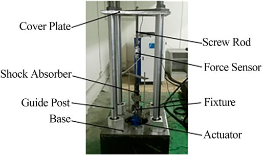
FIGURE 9. Picture of the experimental bench.
During the experiment, it is necessary to ensure the vertical installation of the damper. The lower lug of the damper is connected to the actuator through a clamp, and the upper end of the damper is connected to a force sensor to adjust the gear of the damper. The test method of fixed stroke and variable frequency is adopted.
According to the vibration speed of the damper, the excitation frequencies of the corresponding actuators are set at 0.16, 0.42, 0.83, 1.24, and 1.66 Hz, respectively (Xie et al., 2015). After three to five working cycles, according to the damping force and displacement signals collected by the acquisition card, the characteristic curves of the indicator diagram under each excitation frequency are drawn, as shown in Figure 10 and Table 2.
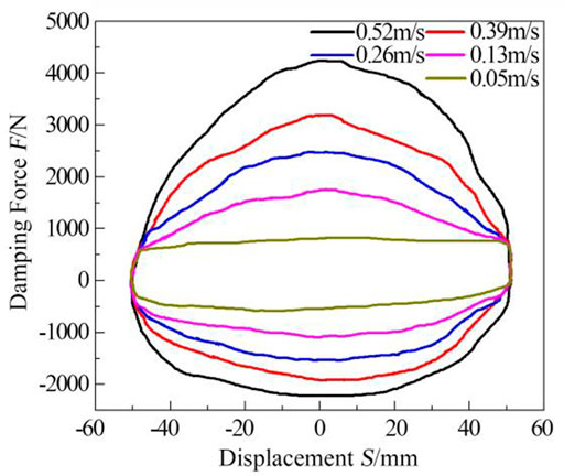
FIGURE 10. Indicator diagram of the damper.
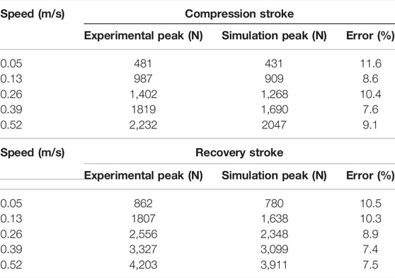
TABLE 2. Comparison of damping peak values of the simulation and test.
Comparing Figures 8 and 10, there are found that the experimental curve does not have distortion, and the contour of the indicator diagram is similar to the simulation curve. With the increase of the excitation speed, the damping force also increases. The maximum damping force appears at the stroke center of the damper. At the same time, the absolute value of the recovery damping force is greater than the compression damping force, and the damping force is not distorted. As shown in Table 2, under the five experimental speeds, the maximum error between the experimental peak and the simulation peak is 11.6%, and the average error of the peak is 9.15%, which indicates that the established mathematical model can better describe the working state of the damper.
Design of experiments (DOE) is a structured mathematical-statistical method (Montgomery, 2009). Through small-scale experiments and experimental data analysis, the influence of different control parameters on one or more target functions can be compared, and the key experimental factors can be identified. Through the experimental design, the influence of various design variables on damping characteristics can be explored, and the key design variables can be selected to reduce the design cost.
The damping contribution rate reflects the percentage of damping force of different parameters in the damping work process. The key design parameters are initially screened, the upper and lower limits of each parameter are given, the cumulative damping force of each key parameter is calculated, and the damping contribution rate of different parameters is obtained.
DOE is essentially a mathematical model, which aims to find the relationship between factors and response. It is generally divided into three stages: experiment plan, experiment execution, and experiment result in analysis.
Many factors affect the damping characteristics of the valve-controlled adjustable damper. To improve the efficiency of experimental design, the key parameters such as the constant through-hole diameter, the valve plate equivalent thickness and the valve plate pre-tightening force of the two check valves “a” and “b” are selected as DOE experimental factors. Table 3 shows the selected experimental factors and their level values.
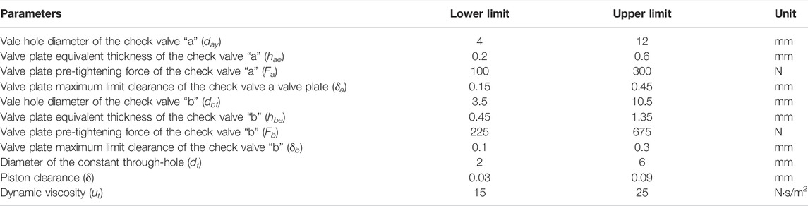
TABLE 3. Parameter level values of influencing factors of damping characteristics.
According to the research purpose, the damping work of the compression stroke is determined as the response under different excitation speeds of 0.05, 0.13, 0.26, 0.52, and 1 m/s.
In ISIGHT, DOE components in-process components and Matlab interface components in application components are used to build the simulation process. The structural parameters and oil parameters of the damping control valve are internal parameters, and the external excitation is external parameters. The experiment includes two strokes of restoration and compression, five excitation speeds for each stroke, seven factors for each stroke, and two levels for each factor, run ISIGHT, and get the final result after calculation.
Figure 11 shows the damping contribution rate of each parameter in the compression stroke under different excitation speeds. In the figure, the left axis represents the damping contribution rate of the parameter, and the right axis represents the cumulative percentage of the parameter.
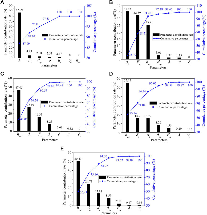
FIGURE 11. The damping contribution rate of each parameter to the compression stroke under different excitation speeds (%). Note: Excitation speeds: (A) 0.05 m/s (B) 0.13 m/s (C) 0.26 m/s (D) 0.52 m/s (E) 1 m/s.
Figure 11A shows that when the excitation speed is 0.05 m/s, the damping contribution rate of the constant through-hole diameter is the largest, reaching 87.09%; Other parameters such as the valve plate pre-tightening force of the check valve “a” and the valve hole diameter of the check valve “a” contribute less than 5%. This is because when the excitation speed is 0.05 m/s, the check valve “a” is in the state before the first opening, and the damping force is basically generated by the constant through-hole at this stage, and other parameters have little influence on the damping work of the whole compression stroke.
Figure 11B shows that when the excitation speed is 0.13 m/s, the damping contribution rate of the constant through-hole diameter, the valve plate pre-tightening force of the check valve “a”, and the valve plate equivalent thickness of the check valve “a” are larger, and the cumulative contribution rate of the three reaches 94.22%. The damping contribution rate of the constant through-hole diameter decreased. This is because when the valve is opened for the first time, the damping force is mainly provided by the through-hole and the annular gap.
Figure 11C shows that when the excitation speed is 0.26 m/s, the damping contribution rate of the valve plate equivalent thickness, the constant through-hole diameter, and the valve plate pre-tightening force of the check valve “a” are in the top three respectively, and their cumulative contribution rate reaches 90.57%. The damping contribution rate of the valve plate equivalent thickness of the check valve “a” increases, while the valve plate pre-tightening force of the check valve “a” decreases, and the damping contribution rate of the constant through-hole diameter further decreases. The reason is that the influence of the stage between the first opening and the second opening on the damping characteristics is mainly determined by the annular gap caused by the deformation of the valve plate.
Figure 11D shows that when the excitation speed is 0.52 m/s, the parameter with the largest damping contribution rate is the valve plate equivalent thickness of the check valve “a”, reaching 55.14%; The damping contribution rate of the valve plate maximum limit clearance of the check valve “a” increased from the seventh to the second, accounting for 15.9%. The damping contribution rate of the constant through-hole diameter and the valve plate pre-tightening force of the check valve “a” further decreased. This is because when the valve is opened in the second stage, the value of the valve plate maximum limit clearance of the check valve “a” directly determines the flow area of the annular gap. The reason for the decrease of the damping contribution rate of the constant through-hole diameter and the valve plate pre-tightening force of the check valve is similar to that when the excitation speed is 0.26 m/s, so it will not be repeated.
Figure 11E shows that when the excitation speed is 1 m/s, the parameters with the largest damping contribution rate are the valve plate equivalent thickness of the check valve “a” and the valve plate maximum limit clearance of check valve “a”, and the cumulative contribution rate of both is 75.16%.
The damping contribution of the constant through-hole diameter decreases gradually after the valve is opened for the first time. With the increase of the excitation speed, the valve plate equivalent thickness and the valve plate maximum limit clearance of the check valve gradually play a major role in the damping contribution rate. The mathematical modeling of the compression stroke and the recovery stroke is similar to the experimental design process. The discussion of the damping contribution rate of the key parameters in the recovery stroke is similar to that of the compression stroke, so it will not be repeated.
A valve-controlled damper with adjustable damping is developed and its damping characteristics are studied. The mathematical model of the damping characteristics of the valve-controlled adjustable damper before and after the opening valve is established, and the damping contribution rate of each parameter of the damping control valve is obtained. Detailed conclusions are presented below.
(a) The peak error of experiment and simulation is within the acceptable range, the damping force has no distortion, and the mathematical model of damping characteristics before and after opening the valve can better describe the working state of the damper.
(b) The simulation obtains the damping contribution rate of each parameter of the compression stroke damping control valve. When the excitation speed is 0.05 m/s, the damping contribution rate of the constant through-hole diameter is 87.09%; When the excitation speed is 0.13 and 0.26 m/s, the damping contribution rate of the constant through-hole diameter, valve plate pre-tightening force of the check valve “a”, and the valve plate equivalent thickness of the check valve “a” are larger, and the cumulative contribution rate of the three is 94.22 and 90.57%, respectively; When the excitation speed is 0.52 m/s, the parameter with the largest damping contribution rate is the valve plate equivalent thickness of the check valve “a”, reaching 55.14%. When the excitation speed is 1 m/s, the parameters with the largest damping contribution rate are the valve plate equivalent thickness of the check valve “a” and the valve plate maximum limit clearance of the check valve “a”, and their cumulative contribution rate reaches 75.16%.
(c) The damping contribution of the constant through-hole diameter decreases gradually after the valve is opened for the first time. With the increase of the excitation speed, the valve plate equivalent thickness and the valve plate maximum limit clearance of the check valve “a” gradually play a major role in the damping contribution rate.
(d) The research results of this paper can screen out the key design variables, improve the development efficiency of the damper, and provide reference and guidance for the damper design and optimization.
The original contributions presented in the study are included in the article/Supplementary Material, further inquiries can be directed to the corresponding author.
FX and XS carried out conceptualization, writing the original manuscript, and revising. JC and ZD did methodology development, model design, and data collection. CY participated in the experiments and manuscript revision. YG did results discussion and language polish.
FX was supported by the Fundamental Research Funds for the Central Universities (2020ZDPYMS20).
The authors declare that the research was conducted in the absence of any commercial or financial relationships that could be construed as a potential conflict of interest.
All claims expressed in this article are solely those of the authors and do not necessarily represent those of their affiliated organizations, or those of the publisher, the editors and the reviewers. Any product that may be evaluated in this article, or claim that may be made by its manufacturer, is not guaranteed or endorsed by the publisher.
The author(s) disclosed receipt of the following financial support for the research, authorship, and/or publication of this article: The authors would like to acknowledge the financial supports given by the Fundamental Research Funds for the Central Universities (2020ZDPYMS20).
Cao, J. X. (2020). Parameter Optimization of Valve-Controlled Damping Adjustable Shock Absorber Based on Vehicle Ride Comfort. Master’s Dissertation. Zhenjiang, China: Jiangsu University. doi:10.27170/d.cnki.gjsuu.2020.000403
Causemann, P. (2003). Modern Vibration Damping Systems. ATZ Worldw 105 (11), 10–13. doi:10.1007/BF03225190
Chen, L., Yu, L., and Cui, X. L. (2013). Performance Simulation and experiment of Damping Multi-State Switching Shock Absorber. J. Jiangsu Univ. (Natural Sci. Edition) 34 (3), 6–10. doi:10.3969/j.issn.1671-7775.2013.03.001
Ding, E., Xie, F., Dai, H., Gao, Q., Zhang, J., Feng, Y., et al. (2018). Fluid Flow Modeling of a Four-Stage Damping Adjustable Shock Absorber and its Experimental Research. Int. J. Struct. Integrity 9 (1), 17–26. doi:10.1108/IJSI-03-2017-0016
Farjoud, A., Ahmadian, M., Craft, M., and Burke, W. (2012). Nonlinear Modeling and Experimental Characterization of Hydraulic Dampers: Effects of Shim Stack and Orifice Parameters on Damper Performance. Nonlinear Dyn. 67 (3), 1437–1456. doi:10.1007/s11071-011-0079-2
Fu, X. (2016). Research on Valve-Controlled Adjustable Damping Shock Absorber and Damping Characteristics. Glob. Market Inf. Herald 37, 129. CNKI:SUN:HQXX.0.2016-37-102.
Huang, Y. M., Hou, S. J., Qin, D. C., and Wang, T. T. (2020). Theoretical Modeling and Key Parameter Impact Analysis of Built-In Valve-Controlled Damping Adjustable Shock Absorber. Automobile Tech. 532 (1), 37–43. doi:10.19620/j.cnki.1000-3703.20191046
Lindler, J. E., Dimock, G. A., and Wereley, N. M. (2000). Design of a Magnetorheological Automotive Shock Absorber. Proc. SPIE−the Int. Soc. Opt. Eng. 3985, 426–437. doi:10.1117/12.388845
Liu, Z. T., Miao, Y. Y., Zhang, S. B., You, J., and Wei, J. R. (2019). The Development and Research Status of the Shock Absorber Industry in the Automobile Industry. Jiangsu Sci. Tech. Inf. 36 (10), 80–85. doi:10.3969/j.issn.1004-7530.2019.10.024
Łuczko, J., and Ferdek, U. (2019). Non-linear Analysis of a Quarter-Car Model with Stroke-dependent Twin-Tube Shock Absorber. Mech. Syst. Signal Process. 115, 450–468. doi:10.1016/j.ymssp.2018.06.008
Ma, T., Cui, Z. F., and Zhang, M. M. (2013). Modeling and Simulating of the Gas-Precharged Dual-Sleeve Shock Absorber with Multiple Valve Plates Using AMESim. J. Mech. Eng. 49 (12), 123–130. doi:10.3901/JME.2013.12.123
Ma, Y. F. (2018). Design and Research of Multi-point Force Value Vehicle Shock Absorber Based on Multi-Objective Optimization. Master’s Dissertation. Chengdu, China: Southwest Jiaotong University. CNKI:CDMD:2.1018.709778.
Maemor, K., Tanigawa, N., Koganei, R., and Morihara, T. (2003). Optimization of a Semi-active Shock Absorber for Aircraft landing Gear, ASME 2003 International Design Engineering Technical Conferences and Computers and Information in Engineering Conference, Chicago, United states, September 2003. New York, NY: ASME, 597–603. doi:10.1115/detc2003/dac-48765
Montgomery, D. C. (2009). Experimental Design and Analysis. Beijing: China Statistics Press. 978-7-115-19234-9.
Wang, T., Zhou, J., Meng, F. X., and Ji, W. T. (2018). A Structural Optimization Design Method for Train Vertical MR Damper. Mech. manufacturing automation 47 (1), 101–104. doi:10.19344/j.cnki.issn1671-5276.2018.01.029
Wang, Z. Q. (2016). Discussion on the Present Situation and Development of Automobile Shock Absorbers. Tech. Innovation Appl. 159 (11), 151. CNKI:SUN:CXYY.0.2016-11-129.
Xie, F., Ding, E., Xuan, R., Zhang, X., Feng, Y., and Zhu, J. (2018). Influence Rules of Geometric Parameters on Deformation of Valve Slices in Valve-Controlled Adjustable Damping Shock Absorber. Int. J. Struct. Integrity 9 (1), 107–118. doi:10.1108/IJSI-04-2017-0025
Xie, F. W., Xuan, R., and Zhang, B. (2015). Design and Experimental Study of Test Bench for Damping Adjustable Shock Absorber Based on xPC. Automobile Tech. 483 (12), 44–48. doi:10.3969/j.issn.1000-3703.2015.12.011
Xuan, R. (2016). Research on Valve-Controlled Adjustable Damping Shock Absorber and its Damping Characteristics. Master’s Dissertation. Zhenjiang, China: Jiangsu University. doi:10.7666/d.D823375
Yang, M. J., Yu, J. Q., and Guo, Y. B. (2019). Present Situation and Development Tendency of Shock Absorbers in Vehicle Suspensions. ENGINEERING TEST. 59 (2), 97–100. doi:10.3969/j.issn.1674-3407.2019.02.036
Zhang, W. L., Mei, Y. H., and Liu, L. Y. (2019). Research on Optimization of Hydraulic Double Cavity Damping Stiffness Based on Finite Element Method. Mod. manufacturing Technol. equipment 277 (12), 86–89. doi:10.16107/j.cnki.mmte.2019.1210
Zhou, C. C., and Ren, C. B. (2009). Optimum Design of Throttle Slice Thickness and its Characteristic Test for Telescopic Damper with Damping Matching. J. Vibration Eng. 01, 54–59. doi:10.16385/j.cnki.issn.1004-4523.2009.01.008
Fc valve-controlled damping adjustable damper compression stroke damping force, N
Ff friction between the piston and the working cylinder during the compression stroke, N
Fa valve plate pre-tightening force of the check valve “a”, N
Fb valve plate pre-tightening force of the check valve “b”, N
l gap length, m
Ad working cylinder area, m2
Ar piston rod area, m2
Ab contact area between the piston and the working cylinder, m2
At flow area of the constant through-hole, m2
Pn radial pressure on piston, Pa
P0 initial pressure of the nitrogen cavity, Pa
P1 oil pressure of recovery cavity, Pa
P2 oil pressure of compression cavity, Pa
P3 pressure of nitrogen cavity, Pa
ΔP21 pressure difference between the compression cavity and the recovery cavity, MPa
ΔP31 pressure difference at both ends of the check valve “a”, MPa
V0 initial volume of the nitrogen cavity, m3
vc1 piston movement speed of the compression stroke, m/s
vc2 velocity of piston movement after initial valve opening of the compression stroke, m/s
rc1 inner circle radius of the annular disc of the check valve “a”, m
rc2 outer circle radius of the annular disc of the check valve “a”, m
δa valve plate maximum limit clearance of the check valve “a”, mm
δb valve plate maximum limit clearance of the check valve “b”, mm
dd inner diameter of the working cylinder, mm
dr diameter of the piston rod, mm
dt diameter of the constant through-hole, mm
day valve hole diameter of the check valve “a”, mm
dbf valve hole diameter of the check valve “b”, mm
Nt number of the normal through-hole, -
n number of the normal through-hole, -
na number of the check valve “a” hole, -
nb number of the check valve “b” hole, -
Hr contact width between the piston and the working cylinder, m
hae valve plate equivalent thickness of the check valve “a”, mm
hbe valve plate equivalent thickness of the check valve “b”, mm
Ct flow coefficient of the constant through-hole
Ρ oil density, kg/m3
Δ oil film thickness, m
e eccentricity, -
δ piston clearance, mm
xq the nitrogen cavity piston displacement, m
r the temperature index, 1.4
sp the displacement of the piston after the valve is opened, m
Keywords: damping contribution rate, key parameter, valve-controlled, damping characteristics, damper
Citation: Xie F, Shi X, Cao J, Ding Z, Yu C and Gao Y (2022) Research on Damping Contribution Rate of Key Parameters of Valve-Controlled Damping Adjustable Damper. Front. Energy Res. 10:854529. doi: 10.3389/fenrg.2022.854529
Received: 14 January 2022; Accepted: 25 March 2022;
Published: 12 April 2022.
Edited by:
Jin-Hyuk Kim, Korea Institute of Industrial Technology, South KoreaReviewed by:
Hemantha Kumar, National Institute of Technology, IndiaCopyright © 2022 Xie, Shi, Cao, Ding, Yu and Gao. This is an open-access article distributed under the terms of the Creative Commons Attribution License (CC BY). The use, distribution or reproduction in other forums is permitted, provided the original author(s) and the copyright owner(s) are credited and that the original publication in this journal is cited, in accordance with accepted academic practice. No use, distribution or reproduction is permitted which does not comply with these terms.
*Correspondence: Fangwei Xie, eGllZmFuZ3dlaUBjdW10LmVkdS5jbg==
Disclaimer: All claims expressed in this article are solely those of the authors and do not necessarily represent those of their affiliated organizations, or those of the publisher, the editors and the reviewers. Any product that may be evaluated in this article or claim that may be made by its manufacturer is not guaranteed or endorsed by the publisher.
Research integrity at Frontiers
Learn more about the work of our research integrity team to safeguard the quality of each article we publish.