 Shengli Ding
 Shaowen Chen
 Songtao Wang
 Zhongqi Wang
- School of Energy Science and Engineering, Harbin Institute of Technology, Harbin, China
This study concerns a multi-objective optimization of circumferential single grooved casing treatment for a low-reaction transonic rotor with ultra-high loading. The axial location, width and depth of the groove are investigated as design variables. The optimization problem seeks to fully extend the operation range of the rotor while minimizing efficiency degradation. Artificial neural network of radial basis function is applied to construct the surrogate model. The optimal groove configuration was determined using non-dominated sorting genetic algorithm II (NSGA II) in conjunction with technique for order preference by similarity to ideal solution (TOPSIS). Detailed analysis of flow field reveals that two flow features involving stability enhancement for the low-reaction rotor are the inhibition of shock/vortex interaction in the rotor tip region and the reduction or elimination of double-leakage tip gap flow. The blocking region located right downstream of the interface between the tip leakage flow and the main flow is decreased due to the tip unloading effect and recirculation flow induced by the groove. Additionally, the efficiency improvement can be observed as the intensity of tip leakage vortex decreases. Based on the single groove optimization, the prospect of a particular multiple groove casing configuration consisting of component grooves with varied geometrical dimensions is also discussed in the paper. The simulation results indicate that the new-type multiple groove configuration is more advantageous to the rotor’s performance.
Introduction
Increasing the overall pressure ratio is an efficient way to increase the cycle efficiency and energy utilization of a gas turbine. In the case of limited blade speed, increasing the pressure rise per stage will require a higher stage loading. Kerrebrock et al. (1997) pioneered the application of boundary layer aspiration to compressor design. A fully aspirated transonic compressor stage, with aspiration on both the rotor and stator, was designed to experiment. The compressor stage achieved a total pressure ratio of 3.4 at a tip speed of 457 m/s. In comparison to conventional stages, the work capacity can be doubled while maintaining acceptable through-flow efficiency. Unfortunately, as a high-speed rotating component, the aspiration slots on the rotor have the potential for an unfavorable influence on blade mechanical strength, severely limiting the engineering application of the aspiration technique. To address this issue, Hu et al. (2014) proposed an unconventional design strategy: a low-reaction aspirated transonic compressor. By increasing the meridional velocity downstream of the passage shock, the rotor could achieve a higher loading coefficient and avoid large-scale flow separation without using aspiration. As a result, the boundary layer aspiration was limited to the stator. It is worth noting, however, that the difficulty of aerodynamic design for the low-reaction compressor rotor is significantly increased due to the lack of active flow control techniques.
Also, higher compressor loading tends to sacrifice safe operating range. There is a conflict between increasing aerodynamic loading and maintaining adequate stall margin. Numerous studies have established the critical role of rotor tip leakage flow and its associated vortex in stall onset (Adamczyk et al., 1993; Hewkin-Smith et al., 2019; Zhu et al., 2021). Owing to the presence of passage shock, the tip leakage behavior in transonic compressors is much more complicated. Experimental and numerical results from Suder and Celestina (1996) revealed that the interaction of the passage shock and the tip leakage vortex (TLV) may primarily contribute to the stall of a transonic rotor. Increased rotor loading can enhance shock/vortex interaction. Casing treatment has been developed as a viable method for mitigating the adverse impacts of tip leakage flow. In general, casing treatment can be broadly divided into two categories in accordance with its structure: circumferential grooves (Shabbir and Adamczyk, 2005; Mustaffa and Kanjirakkad, 2021) and axial slots (Djeghri et al., 2015; Ba et al., 2020). Both configurations exhibit excellent stability enhancement capability, but they permanently alter the shape of the casing and have a continuous influence on the flow field near the rotor tip throughout the operating range, frequently resulting in efficiency penalties (Sun S et al., 2019). Grooved casing treatment has received particular attention due to the benefits of reduced impact on efficiency and ease of manufacture.
Several parametric studies on the grooved casing treatment for transonic compressors have been conducted. The underlying flow mechanisms are gradually uncovered in the process. Rabe and Hah (2002) investigated the effect of groove depth on stability using a combination of numerical simulations and experiments. It was discovered that both shallow and deep grooves had a positive effect on stall margin. The decrease in the incidence angle is thought to be the main factor in stall margin improvement. On the other hand, Muller et al. (2007) observed that shallow grooves were less effective than deep grooves at extending the stall margin but were more conducive to improving peak efficiency. The calculated Mach number distributions near the casing showed that the interaction between the leakage flow and the recirculation flow of grooves reduced tip blockage, preventing the leakage flow from forward spillage and postponing the stall onset.
More recently, Mustaffa and Kanjirakkad. (2021) numerically investigated the impact of groove axial location on NASA rotor 37. To qualify the near casing blockage in transonic rotors, a novel blockage parameter was proposed. The results indicated that the maximum stall margin increment could be achieved when the groove was located upstream of the peak tip blockage location. It was explained that it is more beneficial to eliminate the front portion of the peak blockage than to reduce the peak blockage itself. Sakuma et al. (2014) also regarded NASA rotor 37 as the research object and studied the influences of groove axial location and depth. The results indicated that the best gain in stall margin occurred at the 20% point of the axial tip chord length (
Despite these parametric studies on casing groove, the design criterion for casing groove is still unclear. In practice, the selection of groove geometrical parameters is heavily reliant on the designer’s experience, which undoubtedly complicates the search for the optimal design. In the wake of developments in computational fluid dynamics and machine learning techniques, several optimization investigations into casing grooves have been launched in recent years. Choi et al. (2010) optimized casing grooves for a transonic rotor using groove depth and width as variables, with the goal of maximizing stall margin. Kim et al. (2011) performed a multiple-objective optimization of casing grooves with a focus on enhancing stall margin and peak efficiency. Zhao et al. (2014) optimized the effect of casing grooves on NASA rotor 37 based on radial basis function neural network (RBFNN) and a multi-objective evolutionary algorithm. In order to improve stability and design performance, Song et al. (2019) developed a grooved casing treatment optimization method integrated with three-dimensional blade design. These optimization studies were conducted on multiple grooves, using identical and equally spaced casing grooves. In particular, Qin et al. (2014) performed optimization of a six-groove configuration with independent depths. They also pointed out that each groove should ideally have a different width, if computing resources permit.
Houghton and Day (2012) argued that the effects of multiple grooved casing treatment were not simply an accumulation of the individual grooves’ effects. Huang et al. (2008) and Choi et al. (2010) found that the groove near the trailing edge was superfluous for stability enhancement. The research of Mirzabozorg et al. (2017) demonstrated that the stall margin improvement of a multiple groove configuration is comparable to that of the upstream single groove. These findings indicate that there are some shortcomings in previous multiple groove optimization studies in which the geometry of each component groove is identical and changes synchronously. During the optimization process, some grooves may be redundant, and the effectiveness of some specific grooves can be hindered.
Besides, in all the studies on casing treatment reviewed here, the subjects were mostly compressors with moderate loading. To date, a detailed research on highly loaded compressor is rare in open literature.
This study presents numerical investigations of grooved casing treatment for a highly loaded low-reaction transonic compressor rotor. A multi-objective optimization is conducted to obtain the best stability-enhancing effect of single circumferential groove while maintaining rotor efficiency. The flow mechanisms governing the grooved casing treatment acting on the rotor are also explored and analyzed. Hence, owing to the presented work, the best values of groove parameters can be revealed, providing design guidelines for promoting the effectiveness of grooved casing treatment in highly loaded compressors. Finally, an unconventional form of multiple grooved treatment is presented and evaluated on the basis of the optimized single groove design.
Model Specifications
The investigated rotor comes from a low-reaction transonic aspirated compressor stage. The design methodology of the unconventional compressor is elaborated in reference (Hu et al., 2014). With the help of this design philosophy, the compressor can achieve an ultra-high loading coefficient with excellent through-flow capacity. The main characteristics of the compressor rotor are summarized in Table 1. The rotor can achieve a total pressure ratio of 2.65 at a tip speed of 370 m/s when operating at peak efficiency (PE).
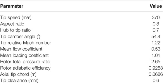
TABLE 1. Main parameters of the investigated compressor rotor at PE.
With respect to the casing treatment design, the parameterization is illustrated in Figure 1. D, W, and Z represent the depth, width, and axial location of the casing groove, respectively, and are all normalized using the axial tip chord length. The parameter ranges are presented in Table 2, which are derived from previous studies on the grooved casing treatment in low-reaction transonic compressors (Zhu et al., 2020) as well as preliminary calculations.
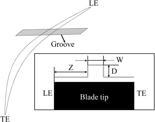
FIGURE 1. Parameterization of grooved casing treatment.
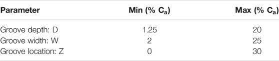
TABLE 2. Ranges of groove parameters.
Numerical Schemes
Computational Scheme
Three-dimensional steady-state simulations are performed using the commercial code EURANUS. The Reynolds-averaged Navier-Stokes equations are discretized using the cell-centered control volume method. The Spalart–Allmaras turbulence model (Spalart and Allmaras, 1992) is used to evaluate the eddy viscosity as it has been proved to commendably capture tip flow structures in transonic compressors by numerous studies (Ren and Gu, 2016; Sun X et al., 2019; Wang et al., 2019).
Total pressure (101325 Pa), total temperature (288.15 K) and inflow angles are taken as the inlet boundary condition. The static pressure condition is imposed with simple equilibrium distribution law at the outlet. As for the solid walls, no-slip and adiabatic conditions are employed. The characteristic lines are obtained by gradually increasing the static pressure at the outlet. The last operating point where the flow parameters exhibit stable periodic fluctuations is set as the near stall (NS) point. When approaching the PE point and stall limit, the step size of the static pressure at the outlet is adapted to 100 Pa, which corresponds to 0.1% of the inlet total pressure.
Grid Strategy
Calculations are carried out using a single blade passage. The blade passage domain is generated by the O4H grid. The rotor tip gap is constructed using a combination of O-type and H-type grids. Within the gap, there are 25 spanwise grid points that efficiently capture tip leakage flow. When calculating the case with casing groove, an additional H-block mesh is used to discretize the groove domain. The full non-matching connecting technique is employed to connect the blade passage and groove region. This technique ensures satisfactory interpolation accuracy and is thus widely used in casing treatment studies (Mao and Liu, 2020; Zhu and Yang, 2020). Furthermore, the minimum grid spacing is set to
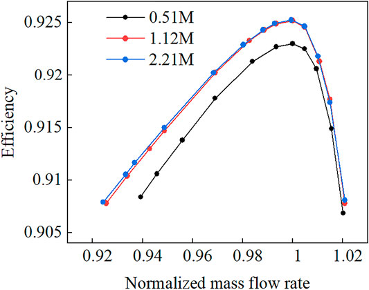
FIGURE 2. Comparison of overall performance with different meshes.
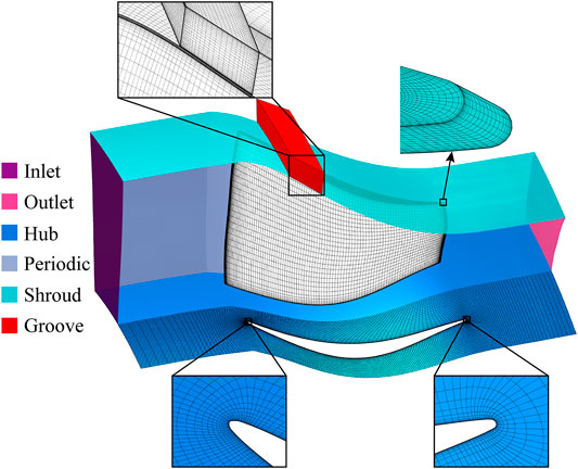
FIGURE 3. Schematic diagram of the total computational domain.
Assessment
In order to demonstrate the reliability and feasibility of the present numerical method, NASA Rotor 67 (Strazisar et al., 1989) is selected for CFD validation. As with the model studied in this work, NASA Rotor 67 is also a low aspect-ratio, transonic rotor, and the stall inception is triggered by the interaction between the passage shock and the TLV. The numerical settings and grid distribution are consistent with that of the investigated rotor. The experimental and calculated data for Rotor 67 are compared in Figure 4, where the abscissa is normalized with the respective choke flowrates for each. The adiabatic efficiency and total pressure ratio are defined as the equations below:
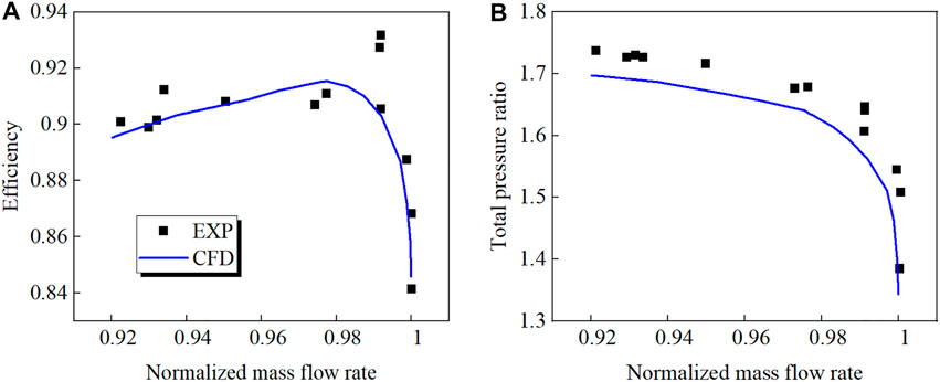
FIGURE 4. Comparison of measured and predicted characteristic lines. (A) Efficiency (B) Total pressure ratio.
As can be seen from Figure 4, the dimensionless flowrate at the NS point predicted by the numerical calculation is 0.92, which is very close to the experimentally measured dimensionless flowrate at the NS point of 0.921. It is demonstrated that the numerical simulation could adequately predict the near stall flowrate. The calculated total pressure ratio curve is underestimated slightly in comparison to the experimental results, within an error of 2.5%. Furthermore, the calculated efficiency is nearly consistent with the experimental data. The efficiency values predicted by simulation at the PE and NS points are 1.75% and 0.6% lower than the experimental results, respectively. On the whole, the selected CFD method is capable of predicting the transonic rotor’s performance and stable operating range with reasonable accuracy.
Multi-Objective Optimization
Peak efficiency and stall margin improvements (PEI and SMI, respectively) are selected as objective functions in order to achieve the optimal effect of casing treatment. SMI is the percentage reduction in mass flow rate at NS produced by the casing treatment, as defined in reference (Houghton and Day, 2012). The two objective functions are calculated using equations:
Furthermore, two optimization constraints are set: one is the boundaries imposed on the decision variables (see Table 2), and the other is that the variation in mass flowrate at PE is less than 2%. The second constraint is used to restrict the performance variation within a certain range after applying the casing treatment. Mathematically, the optimization procedure can be expressed as follows.Maximize:
Subject to:
The optimal Latin hypercube sampling method (OLHS) (Keane et al., 2008) is used for the design of experiment. 28 groove configurations are calculated to generate the database for the surrogate model. In comparison to the traditional Latin hypercube sampling technique, the OLHS method ensures that a design has adequate space filling qualities. RBFNN is employed to construct the surrogate model, which is frequently used to approximate nonlinear relationships and build nonlinear mappings between input and output variables, because it can project low-dimensional linear data into high-dimensional nonlinear data. Additionally, it has a high rate of learning convergence. RBFNN has been successfully applied to the prediction of compressor operating range and performance in recent literature (Vuong et al., 2021). The precision of the surrogate model was evaluated by means of k-fold cross validation.
Non-dominated sorting genetic algorithm II (NSGA II) is adopted to find the optimal solutions. NSGA II (Deb et al., 2002) is a classical multi-objective evolutionary algorithm, which reduces the complexity of non-dominated sorting genetic algorithm and has high operation speed as well as good nature of the constringency of the solution set. It is an effective method for solving multi-objective functions and should be suitable to this investigation. To begin with, a parent population of size N is created. Through crossover and mutation operations, new individuals with higher quality than the previous generation are generated. This process is iterated so that the population always evolves towards the optimal direction from generation to generation. A Pareto-optimal solution set of objective functions is finally obtained when the algorithm terminates. One hundred populations combined with 600 generations are applied in this optimization.
Results and Discussion
Multi-Objective Optimization
As depicted in Figure 5A, the pareto front is provided as the multi-objective optimization results. It can be seen from the distributions of the pareto front that SMI and PEI present a negative relationship. Consequently, the designer should make a compromise between the capacity of stability extension and the impact on adiabatic efficiency for casing treatment and select one point from the pareto set. Technique for order preference by similarity to ideal solution (TOPSIS) (Behzadian et al., 2012), one of the most commonly used methods in multi-objective decision analysis, is employed to search the optimal design point. Due to the high through-flow efficiency and limited stall margin for the investigated rotor, prior consideration is given to the stability enhancement capacity of casing treatment in decision-making. Hence, the final optimal solution is obtained by setting a weight ratio of 7:3 for SMI and PEI, which is denoted as the TOPSIS point in Figure 5A. In addition, the points corresponding to the maximum values of SMI and PEI are also displayed.
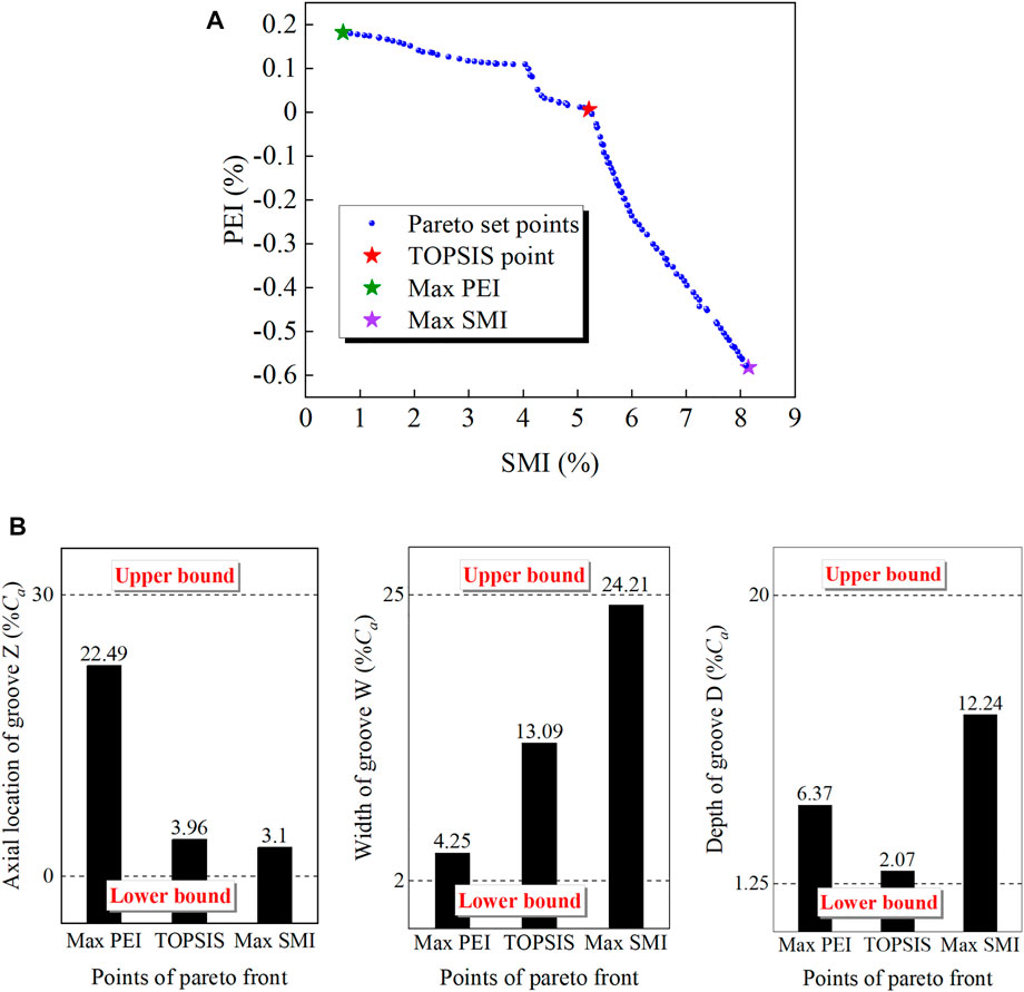
FIGURE 5. Pareto front and geometric parameters of typical points. (A) Pareto front of objective functions (B) Geometric parameters of typical points.
Table 3 compares the surrogate model predictions with the numerical calculation values. The results demonstrate once again the effectiveness and applicability of this surrogate model. Figure 5B shows the design variable values of the three typical points. It is found that widening the groove increases the stall margin but degrades peak efficiency. The groove close to the leading edge provides a substantial increase in the stall margin, and the optimum groove in terms of peak efficiency improvement is located around 20%
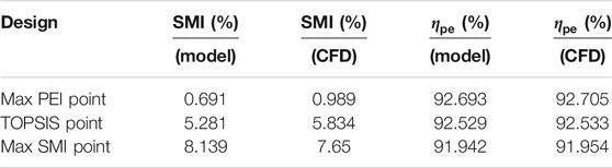
TABLE 3. Ranges of casing groove parameters.
Figure 6 compares the characteristic lines derived from simulations with and without casing treatment. As can be seen from the figure, the max PEI configuration can improve the efficiency and total pressure ratio over the entire flow range, but only slightly increase the stall margin. For the max SMI point, the stall margin can be increased by about 7.65%, but the total pressure ratio and efficiency decrease, and the flowrate reduction at PE approaches the prescribed constraint. The optimal design derived from TOPSIS combines the advantages of the two design cases, without degrading the rotor performance and with a remarkable increase in operating range. As to the aerodynamic performance and stability synthetically, the optimum design is an excellent choice.
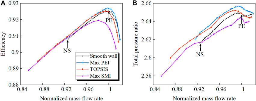
FIGURE 6. Characteristic lines of rotor with and without casing treatment. (A) Efficiency (B) Total pressure ratio.
Flow Mechanisms of Applying Casing Treatment
Changes in Blade Tip Flow Field at NS
In order to elucidate the underlying mechanism by which casing treatment affects stability, this section will focus on the flow fields at NS. Figure 7 shows the vortex structures in the tip region. The passage shock is outlined with a green dotted line. A new vortex identification method is used to visualize the tip vortices, that is the objective Ω method (Liu et al., 2019). Compared to other vortex identification methods such as the Q criterion and the λ2 criterion, the Ω method has advantages in terms of definite physical meaning and normalization (values range from 0 to 1). Vortices are colored with normalized helicity
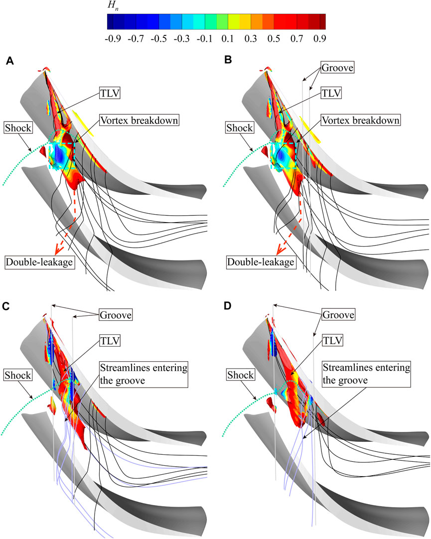
FIGURE 7. Tip vortex structures with and without casing treatment at NS, captured by Ω method. (A) Smooth casing (B) Max PEI point (C) TOPSIS point (D) Max SMI point.
The stability enhancement effect can be intuitively reflected by the nature of TLV. For the smooth casing, the TLV expands sharply both in the radial and tangential directions after passing through the passage shock, and the normalized helicity value along the TLV fluctuates dramatically. These flow features mark the onset of TLV breakdown. Vortex breakdown is always accompanied by reverse flow generation and induces serious tip blockage. Additionally, abundant double leakage fluid is formed as the TLV impinges on the pressure side of the adjacent blade. The double-leakage fluid has a high jet angle relative to the main flow, further resulting in the blocking of the flow in the tip region. For the max PEI point, the groove is located far downstream from the onset of vortex breakdown and therefore has little influence on the development of the TLV. One can see that the TLV breakdown still occurs, but to a lesser extent than with the smooth casing. By contrast, the original vortex breakdown region is covered by the TOPSIS and max SMI configurations, so that the flow structures in the tip region are powerfully influenced. Despite the fact that the vortex structure has been complicated due to the aspiration and injection of the groove, the TLV no longer breaks down. In addition, the double-leakage is well suppressed. The double-leakage flow downstream of the groove is almost totally removed. Under the groove, the fluid enters the groove (purple streamlines) and passes through the blade tip almost in the tangential direction. Its flow angle with respect to the blade tip camber is considerably smaller than that of the double-leakage flow occurring in the smooth casing case at the same location. As a result, the fluid through the groove has a smaller jet angle with respect to the main flow, resulting in a reduction in tip blockage and mixing loss. The above effects contribute to stability enhancement.
Tip leakage flow is driven by the pressure difference between the blade tip pressure side and the suction side. Given that the TLV breakdown occurs close to the leading edge, it is reasonable to speculate that this portion of the leakage flow plays a prominent role in the vortex breakdown and stall inception. In Figure 8, the surface static pressure coefficient distribution at 98% span is compared between grooved and smooth casing conditions. The pressure coefficient is determined by normalizing the rotor inlet total pressure. It can be seen that at the TOPSIS and max SMI points, the leading edge loading decreases obviously under the groove. The groove is equivalent to increasing the tip gap size in the corresponding region, which increases the radial pressure gradient and causes a decreased pressure difference across the blade tip. The decrease in tip loading indicates that the intensity of tip leakage flow is reduced, and so is the swirl strength of TLV. The TLV breakdown is less likely to occur due to the weakened vortex strength. One can also observe that the pressure on the pressure side just downstream of the groove rises. Sakuma et al. (2014) pointed out that the leakage flow downstream of the groove is disturbed by the leakage flow under the groove, which causes the leakage flow to stagnate and results in the pressure increase. As for the max PEI point, the tip loading exhibits a different pattern of variation, with the load below the groove rising instead. This is due to the double-leakage flow is interfered by the flow under the groove on the pressure side.
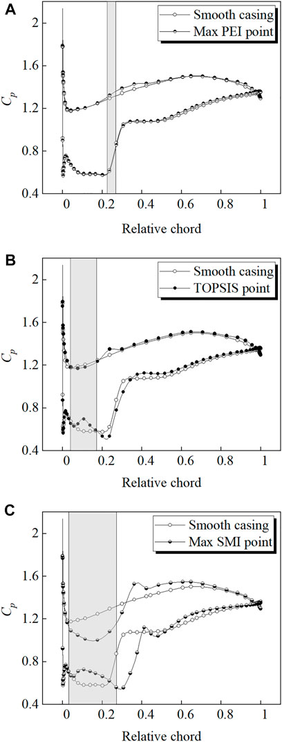
FIGURE 8. Surface static pressure coefficient distribution at 98% span. (A) Max PEI point (B) TOPSIS point (C) Max SMI point.
In addition to the unloading effect, the recirculation flow of the groove also strongly affects the tip flow field. Figure 9 shows the radial momentum distribution at the bottom surface of groove. The static pressure coefficient contours at 98% span are also shown in the figure. The trajectory of TLV can be traced by the static pressure troughs. It can be seen that the positive radial momentum zone is located near the blade pressure side, corresponding to the leakage flow being aspirated into the groove. At the TOPSIS and max SMI points, the groove is located above the passage shock, which enhances the driving force of the recirculation, and the flow near the suction side after the shock is also inhaled into the groove. The flow inside the groove appears to be reinjected into the tip passage along the trajectory of TLV. Typically, a low pressure region can be found upstream of the passage shock near the blade suction side. Abundant leakage fluid flows towards this region, causing the blocking of the flow and the roll up of TLV. The recirculation flow energizes the low pressure region. So that, the roll up of TLV is delayed and the starting point of the TLV trajectory is shifted downstream. Meanwhile, the passage shock moves downstream as the tip blockage is reduced. But for the max PEI point, the flow exchange between the groove and the tip region is negligible and has no perceptible impact on the TLV and the shock position. To quantify the capacity of recirculation flow among different configurations, the injection flow rate from the groove is given in Figure 10. This can partly explain why the max SMI point is the best in terms of stability enhancement.
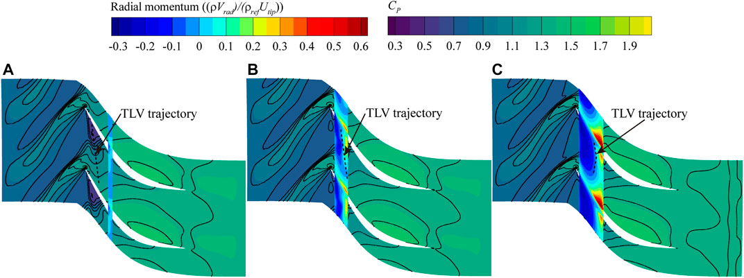
FIGURE 9. Radial momentum at groove bottom surface and
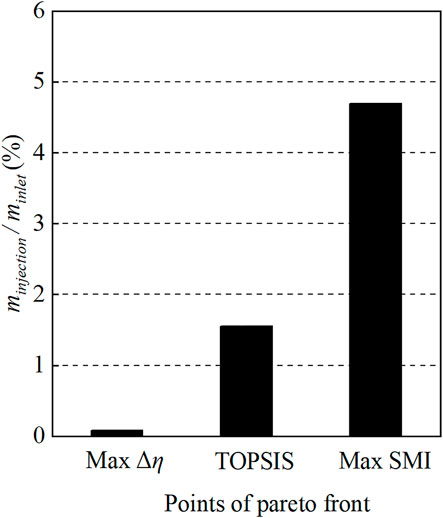
FIGURE 10. Comparisons of the injection flow rate of different design points.
From the perspective of dynamics, the momentum balance between main flow and tip leakage flow is a key factor affecting the compressor stability (Vo et al., 2008). Numerous researchers have demonstrated that stall is initiated when the main flow/tip leakage flow interface spills out of the blade leading edge, both computationally (Mao and Liu, 2020; Zhu et al., 2020) and experimentally (Hah et al., 2010; Cameron et al., 2013). Figure 11 shows the entropy contours and velocity vectors at 98% span. The interface can be identified by a very high entropy gradient region, which is denoted by a yellow dotted line. From the comparison, one can see that the increase in stall margin presents a positive correlation with the distance that the interface is pushed downstream. For the smooth casing, a reverse flow region with high entropy values is located right downstream the interface. This region is formed as a result of the TLV/shock interaction, and hinders the flow to pass through the tip passage smoothly. With the blocking of the reverse flow region, the interface is nearly pushed out of the leading edge plane. In the two configurations with higher SMI, the flow in this region is deflected in the axial direction, and the entropy value is reduced. The max SMI point shows a higher extent of flow deflection, indicating a better flow capacity in the tip region.
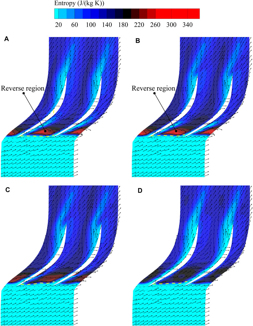
FIGURE 11. Entropy contours and velocity vectors at 98% span. (A) Smooth casing (B) Max PEI point (C) TOPSIS point (D) Max SMI point.
Casing Treatment Impacts at PE
The impact of casing treatment on compressor efficiency is mainly reflected in two aspects. First, the flow exchange between the casing treatment configuration and the tip passage will cause the efficiency to degrade. On the other hand, the control of tip leakage flow by the casing treatment will reduce the flow loss, thereby increasing the efficiency. This section will focus on the flow characteristics under the action of casing treatment at PE.
Figure 12 presents the spanwise distribution of the pitch averaged adiabatic efficiency at the rotor outlet. The max PEI point increases the efficiency in the region above the 70% span because of the effective suppression of tip leakage flow, and has little impact on the efficiency in the lower span. The TOPSIS point preserves closely the radial efficiency distribution of the smooth casing, indicating that there exists a balance between the loss generation and reduction induced by the casing treatment. For the max SMI point, the efficiency is evidently reduced above the 30% span, which suggests that the recirculation flow brings about extensive additional loss, not limited to the tip region.
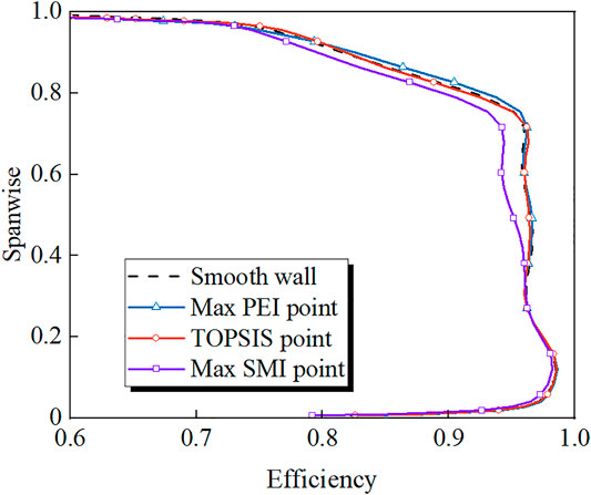
FIGURE 12. Spanwise distribution of pitch averaged adiabatic efficiency at the rotor outlet.
Figure 13 shows the injection mass flow rate and the internal flow loss for the three casing treatment configurations. According to the definition in reference (Zhu and Yang, 2020), the internal flow loss of the groove is calculated as follows:
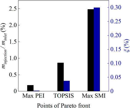
FIGURE 13. Comparisons of the injection flow rate and the loss of different design points.
One can see from the figure that the injection flow of the three configurations appears different varies compared to that under condition NS: the max PEI configuration increases, but the other two configurations decrease. This is because the groove of the max PEI point is located above the intersection point of the passage shock with the blade suction side at PE. The driving force for the recirculation flow is enhanced. But even so, the injection flow rate is still very small compared with the other two configurations, so the additional mixing loss near the blade tip is minimal. Meanwhile, the flow loss inside the groove is nearly negligible for the maximum PEI configuration, but significantly greater for the other two configurations.
The contours of the pitch averaged absolute vorticity coefficient near the blade tip for each casing condition are shown in Figure 14. The absolute vorticity coefficient is defined as follows:
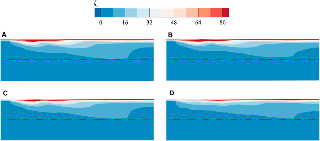
FIGURE 14. Pitch-averaged absolute vorticity coefficient contours near the tip region. (A) Smooth casing (B) Max PEI point (C) TOPSIS point (D) Max SMI point.
The red dash-dotted line in the figure represents the lower boundary of the high absolute vorticity region in the smooth casing condition. As expected, the high vorticity region is reduced at the max PEI point. In order to quantify the intensity of TLV, the integral of the pitch averaged absolute vorticity at the meridional plane is calculated. The integral values of the max PEI, TOPSIS, and SMI points are 0.0629, 0.0633, and 0.0632, respectively. Compared to the smooth casing condition with an integral value of 0.0637, the three casing treatments all decrease the intensity of TLV, with the max PEI point having the greatest reduction. Given that the additional loss caused by the flow exchange between the groove and the tip passage is relatively small, the efficiency for the max PEI point is improved accordingly.
Multiple Grooves
As mentioned in the literature review, almost all previous research on multiple grooved casing treatment has used identical component grooves, but it seems there is no evidence to prove that such a design is necessary. In this section, a novel multiple-groove casing treatment design strategy, which is composed of component grooves with varied geometrical dimensions, is introduced and discussed. Since the behavior of tip leakage vortex changes drastically as it moves downstream within the blade passage, it is logical to allow the geometrical dimensions of each individual groove in multiple grooved casing treatments to vary.
First, the grooves of the optimal design point (TOPSIS point) and the max PEI point are combined into one multiple-groove casing treatment, named M1. For comparison, the downstream groove of M1 is replaced by an identical groove as that of the TOPSIS point to assemble into another multiple-groove casing treatment, denoted by M2. The two multiple-groove casing treatments are shown schematically in Figure 15A. The performance curves of M1 and M2 are compared against the TOPSIS point in Figure 15B. It is found that the peak efficiency of both multiple-groove treatments is higher than that of the TOPSIS point, especially for M1. The SMI of M1 is comparable to that of the TOPSIS point. For M2, however, the SMI is 0.9% lower than the TOPSIS point. A similar phenomenon was also observed in Houghton’s research when the third groove was added to the two-groove treatment. The contrast shows that varying the groove geometrical dimensions may be necessary in some cases of multiple-groove casing treatments.
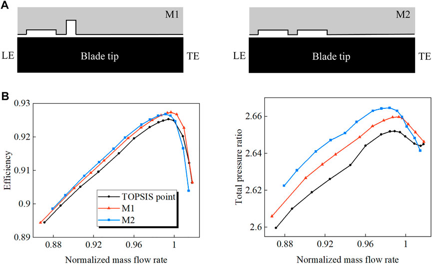
FIGURE 15. Schematic diagram and characteristic lines of the multiple-groove casing treatments. (A) Groove schematic (B) Characteristic lines.
Conclusion
In the presented work, a multi-objective optimization is conducted to maximize the effect of the single grooved casing treatment on an ultra-highly loaded low-reaction transonic rotor. The flow behaviors that lead to performance changes have been carefully analyzed. There is also discussion of an unconventional form of multiple grooved casing treatment. The main conclusions are summarized as follows:
(1) An optimized groove configuration that increases the rotor stall margin by about 5.8% is obtained without efficiency degradation and distinctive characteristic changes. The groove located around the leading edge has good stability-enhancing performance, and the groove located around 20%
(2) In the investigated highly-loaded transonic rotor, the breakdown of TLV is observed at the NS point. The flow blockage near the leading edge caused by the vortex breakdown and double-leakage flow is responsible for the flow instability of the transonic rotor. The tip flow filed analysis shows that the optimized grooved casing treatment can suppress the shock/TLV interaction and double-leakage flow. The presence of casing groove generates the radial migration of tip leakage flow, resulting in the tip unloading and aspiration-injection effects. Influenced by the above effects, the swirl strength of TLV is decreased while the roll up of TLV is delayed. Thus, the TLV has a diminished chance of breaking down under the action of the passage shock. As the shock/vortex interaction is weakened, the flow capacity near the tip region is enhanced, which can be observed from the removal of the reverse flow region located downstream of the main flow/tip leakage flow interface. Consequently, the interface is pushed downstream and the tip stall is eventually postponed.
(3) The groove helps to mitigate the intensity of the tip leakage vortex and thus the associated blockage. When the additional loss induced by the flow exchange between the groove and the tip passage is relatively small, the peak efficiency of the rotor can be improved.
(4) Two kinds of multiple-groove casing treatment have been tested. The first treatment consists of component grooves with varied geometrical dimensions, which achieves a comparable SMI as the single groove and has higher peak efficiency. The second treatment is a conventional design with identical grooves, which causes a decrease in stall margin compared to the single groove. The results reflect that a change in the groove geometrical dimensions along the blade chord is required to control rationally different portions of tip leakage flow for the investigated rotor.
Data Availability Statement
The original contributions presented in the study are included in the article/Supplementary Material, further inquiries can be directed to the corresponding author.
Author Contributions
SD provides innovation, numerical simulation experiment, model establishment and writing for this article. SC provides financial support and guidance about the content of the article. SW and ZW engage in some technical work.
Funding
This work is supported by the National Natural Science Foundation of China (Grant Nos. 52076052 and 51776048) and National Science and Technology Major Project of China (Grant Nos. Y2019-VIII-0013-0174).
Conflict of Interest
The authors declare that the research was conducted in the absence of any commercial or financial relationships that could be construed as a potential conflict of interest.
Publisher’s Note
All claims expressed in this article are solely those of the authors and do not necessarily represent those of their affiliated organizations, or those of the publisher, the editors and the reviewers. Any product that may be evaluated in this article, or claim that may be made by its manufacturer, is not guaranteed or endorsed by the publisher.
Abbreviations
References
Adamczyk, J. J., Celestina, M. L., and Greitzer, E. M. (1993). The Role of Tip Clearance in High-Speed Fan Stall. J. Turbomach. 115 (1), 28–38. doi:10.1115/1.2929212
Agha Seyed Mirzabozorg, M., Bazazzadeh, M., and Hamzezade, M. (2017). Numerical Study on the Effect of Single Shallow Circumferential Groove Casing Treatment on the Flow Field and the Stability of a Transonic Compressor. Jafm 10 (1), 257–265. doi:10.18869/acadpub.jafm.73.238.26480
Ba, D., Zhang, Q., Du, J., Li, Z., Zhang, H., and Nie, C. (2020). Design Optimization of Axial Slot Casing Treatment in a Highly-Loaded Mixed-Flow Compressor. Aerospace Sci. Tech. 107, 106262. doi:10.1016/j.ast.2020.106262
Behzadian, M., Khanmohammadi Otaghsara, S., Yazdani, M., and Ignatius, J. (2012). A State-Of The-Art Survey of TOPSIS Applications. Expert Syst. Appl. 39 (17), 13051–13069. doi:10.1016/j.eswa.2012.05.056
Cameron, J. D., Bennington, M. A., Ross, M. H., Morris, S. C., Du, J., Lin, F., et al. (2013). The Influence of Tip Clearance Momentum Flux on Stall Inception in a High-Speed Axial Compressor. J. Turbomach. 135 (5), 051005. doi:10.1115/1.4007800
Choi, K.-J., Kim, J.-H., and Kim, K.-Y. (2010). Design Optimization of Circumferential Casing Grooves for a Transonic Axial Compressor to Enhance Stall Margin. ASME Paper GT2010-22396. doi:10.1115/GT2010-22396
Deb, K., Pratap, A., Agarwal, S., and Meyarivan, T. (2002). A Fast and Elitist Multiobjective Genetic Algorithm: NSGA-II. IEEE Trans. Evol. Computat. 6 (2), 182–197. doi:10.1109/4235.996017
Djeghri, N., Vo, H. D., and Yu, H. (2015). Parametric Study for Lossless Casing Treatment on a Mixed-Flow Compressor Rotor. ASME Paper GT2015-42750. doi:10.1115/GT2015-42750
Hah, C., Voges, M., Mueller, M., and Schiffer, H.-P. (2010). Characteristics of Tip Clearance Flow Instability in a Transonic Compressor. ASME Paper GT2010-22101. doi:10.1115/GT2010-22101
Hewkin-Smith, M., Pullan, G., Grimshaw, S. D., Greitzer, E. M., and Spakovszky, Z. S. (2019). The Role of Tip Leakage Flow in Spike-type Rotating Stall Inception. J. Turbomach. 141 (6), 061010. doi:10.1115/1.4042250
Houghton, T., and Day, I. (2012). Stability Enhancement by Casing Grooves: The Importance of Stall Inception Mechanism and Solidity. J. Turbomach. 134 (2), 021003. doi:10.1115/1.4002986
Huang, X., Chen, H., and Fu, S. (2008)., CFD Investigation on the Circumferential Grooves Casing Treatment of Transonic Compressor. ASME Paper GT2008-51107. doi:10.1115/GT2008-51107
Keane, A., Forrester, A., and Sobester, A. (2008). Engineering Design via Surrogate Modelling: A Practical Guide. Chichester: Wiley.
Kerrebrock, J. L., Reijnen, D. P., Ziminsky, W. S., and Smilg, L. M. (1997). Aspirated Compressors. ASME Paper 97-GT-525. doi:10.1115/97-GT-525
Kim, J.-H., Choi, K.-J., Husain, A., and Kim, K.-Y. (2011). Multiobjective Optimization of Circumferential Casing Grooves for a Transonic Axial Compressor. J. Propulsion Power 27 (3), 730–733. doi:10.2514/1.50563
Liu, J.-m., Gao, Y.-s., Wang, Y.-q., and Liu, C. (2019). Objective omega Vortex Identification Method. J. Hydrodyn. 31 (3), 455–463. doi:10.1007/s42241-019-0028-y
Mao, X., and Liu, B. (2020). Investigation of the Casing Groove Location Effect for a Large Tip Clearance in a Counter-rotating Axial Flow Compressor. Aerospace Sci. Tech. 105, 106059. doi:10.1016/j.ast.2020.106059
Mao, X., Liu, B., Tang, T., and Zhao, H. (2018). The Impact of Casing Groove Location on the Flow Instability in a Counter-rotating Axial Flow Compressor. Aerospace Sci. Tech. 76, 250–259. doi:10.1016/j.ast.2018.01.037
Mustaffa, A. F., and Kanjirakkad, V. (2021). Single and Multiple Circumferential Casing Groove for Stall Margin Improvement in a Transonic Axial Compressor. J. Turbomach. 143 (7), 071010. doi:10.1115/1.4050444
Mu¨ller, M. W., Schiffer, H.-P., and Hah, C. (2007). Effect of Circumferential Grooves on the Aerodynamic Performance of an Axial Single-Stage Transonic Compressor. ASME Paper GT2007-27365. doi:10.1115/GT2007-27365
Qin, N., Carnie, G., Wang, Y., and Shahpar, S. (2014). Design Optimization of Casing Grooves Using Zipper Layer Meshing. J. Turbomach. 136 (3), 031002. doi:10.1115/1.4024650
Rabe, D. C., and Hah, C. (2002). Application of Casing Circumferential Grooves for Improved Stall Margin in a Transonic Axial Compressor. ASME Paper GT2002-30641. doi:10.1115/GT2002-30641
Ren, X., and Gu, C. (2016). A Numerical Study on the Tip Clearance in an Axial Transonic Compressor Rotor. Appl. Therm. Eng. 103, 282–290. doi:10.1016/j.applthermaleng.2016.04.082
Sakuma, Y., Watanabe, T., Himeno, T., Kato, D., Murooka, T., and Shuto, Y. (2014). Numerical Analysis of Flow in a Transonic Compressor with a Single Circumferential Casing Groove: Influence of Groove Location and Depth on Flow Instability. J. Turbomach. 136 (3), 031017. doi:10.1115/1.4025575
Shabbir, A., and Adamczyk, J. J. (2005). Flow Mechanism for Stall Margin Improvement Due to Circumferential Casing Grooves on Axial Compressors. J. Turbomach. 127 (4), 708–717. doi:10.1115/1.2008970
Song, W., Zhang, Y., Chen, H., and Deng, K. (2019). Transonic Compressor Blade Optimization Integrated with Circumferential Groove Casing Treatment. J. Turbomach. 141 (3), 031015. doi:10.1115/1.4041699
Spalart, P., and Allmaras, S. (1992). A One-Equation Turbulence Model for Aerodynamic Flows. AIAA Paper No. 92-0439. doi:10.2514/6.1992-439
Strazisar, A. J., Hathaway, M. D., Suder, K. L., and Wood, J. R. (1989). Laser Anemometer Measurements in a Transonic Axial Flow Compressor rotorNASA Report No. NASA TP-2879.
Suder, K. L., and Celestina, M. L. (1996). Experimental and Computational Investigation of the Tip Clearance Flow in a Transonic Axial Compressor Rotor. J. Turbomach. 118 (2), 218–229. doi:10.1115/1.2836629
Sun, S., Wang, S., Chen, S., Tao, C., Cai, L., and Chen, J. (2019). The Impact of Various Forward Sweep Angles on the Performance of an Ultra-high-load Low-Reaction Transonic Compressor Rotor. Appl. Therm. Eng. 150, 953–966. doi:10.1016/j.applthermaleng.2019.01.045
Sun, X., Dong, X., and Sun, D. (2019). Recent Development of Casing Treatments for Aero-Engine Compressors. Chin. J. Aeronautics 32 (1), 1–36. doi:10.1016/j.cja.2018.11.005
Vo, H. D., Tan, C. S., and Greitzer, E. M. (2008). Criteria for Spike Initiated Rotating Stall. J. Turbomach. 130 (1), 011023. doi:10.1115/1.2750674
Vuong, T.-D., Kim, K.-Y., and Dinh, C.-T. (2021). Recirculation-groove Coupled Casing Treatment for a Transonic Axial Compressor. Aerospace Sci. Tech. 111, 106556. doi:10.1016/j.ast.2021.106556
Wang, W., Lu, J.-l., Luo, X.-q., and Chu, W.-l. (2019). Coupling Method of Stability Enhancement Based on Casing Treatments in an Axial Compressor. Aerospace Sci. Tech. 95, 105449. doi:10.1016/j.ast.2019.105449
Yingjiao, H., Songtao, W., Longxing, Z., and Jun, D. (2014). Aerodynamic Design of a Highly Loaded Supersonic Aspirated Axial Flow Compressor Stage. Proc. Inst. Mech. Eng. A: J. Power Energ. 228 (3), 241–254. doi:10.1177/0957650913515668
Zhao, Q., Zhou, X., and Xiang, X. (2014). Multi-objective Optimization of Groove Casing Treatment in a Transonic Compressor. Proc. Inst. Mech. Eng. Part A: J. Power Energ. 228 (6), 626–637. doi:10.1177/0957650914532266
Zhu, G., and Yang, B. (2020). Optimization of Slots-Groove Coupled Casing Treatment for an Axial Transonic Compressor. J. Turbomach. 142 (8), 081003. doi:10.1115/1.4046047
Zhu, M., Teng, J., and Qiang, X. (2021). Unsteady Near-Stall Flow Mechanisms in a Transonic Compressor Rotor at Different Rotating Speeds. Aerospace Sci. Tech. 119, 107124. doi:10.1016/j.ast.2021.107124
Keywords: highly-loaded transonic compressor, casing treatment, optimization design, stability, aerodynamic performance
Citation: Ding S, Chen S, Wang S and Wang Z (2022) Multi-Objective Optimization of Circumferential Groove Casing Treatment in an Ultra-Highly Loaded Low-Reaction Transonic Compressor Rotor. Front. Energy Res. 10:853360. doi: 10.3389/fenrg.2022.853360
Received: 12 January 2022; Accepted: 02 March 2022;
Published: 23 March 2022.
Edited by:
Chungen Yin, Aalborg University, DenmarkCopyright © 2022 Ding, Chen, Wang and Wang. This is an open-access article distributed under the terms of the Creative Commons Attribution License (CC BY). The use, distribution or reproduction in other forums is permitted, provided the original author(s) and the copyright owner(s) are credited and that the original publication in this journal is cited, in accordance with accepted academic practice. No use, distribution or reproduction is permitted which does not comply with these terms.
*Correspondence: Shaowen Chen, Y3N3ZW1haWxAaGl0LmVkdS5jbg==