 Pengcheng Yang
 Shaowen Chen
 Weihang Li
 Cong Zeng
95% of researchers rate our articles as excellent or good
Learn more about the work of our research integrity team to safeguard the quality of each article we publish.
Find out more
ORIGINAL RESEARCH article
Front. Energy Res. , 22 March 2022
Sec. Advanced Clean Fuel Technologies
Volume 10 - 2022 | https://doi.org/10.3389/fenrg.2022.853166
This article is part of the Research Topic Advanced Technologies in Flow Dynamics and Combustion in Propulsion and Power View all 25 articles
The boundary layer development on a low-pressure turbine blade surface modified by recessed dimples, U-grooves, and rectangular grooves has been investigated through the large-eddy simulations. The simulations are performed at a Reynolds number of 50,000 (based on the inlet velocity and axial chord length) and extremely low freestream turbulence conditions. The characteristic parameters of the boundary layer are used to estimate the development of the boundary layer, and spectral analysis has also been performed to identify the dominant frequency of shedding vortices. The results of simulations indicate that three surface modifications all reduce the profile losses by restraining the separation bubble size. However, the grooves and dimples show different mechanisms in inhibiting laminar separation. Grooves tend to promote the formation of spanwise vortices, which is more difficult to break into turbulence. A high-speed shedding vortex is induced by the particular 3D structure of dimple, and its shedding frequency is nearly twice the Kelvin–Helmholtz (K-H) instability frequency. The interaction between the shedding vortices and the K-H vortices promotes the breakdown process of the spanwise vortices, which leads to an earlier transition of the boundary layer at a low disturbance level. The current study reveals the different mechanisms of dimples and grooves and shows the great potential of dimples for flow control in low-pressure turbines. Besides, the flow structures inside the dimples with adverse pressure gradients are also explored.
Modern aircraft are designed to have a higher cruising altitude and better engine performance with a larger thrust-to-weight ratio to have a better stealth performance and reduce energy consumption. However, these would lead to the low Reynolds number operation conditions and higher loading of the blade in a low-pressure turbine (LPT), respectively (Houtermans et al., 2004; Praisner et al., 2008; Ji et al., 2021). These characteristics of the LPT stage make the boundary layer on the aft portion of the blade suction side remain laminar and suffer greater pressure gradients. Hence, it is easier to separate from the wall (Volino, 2008). The separation would lead to significant efficiency losses of the engine, as has been described by Lyall et al. (2011). Therefore, exploring proper methods to solve this problem is significant to improving the engine performance.
A mass of active and passive flow control strategies have been implemented to delay or prevent the boundary layer separation on the LPT blade’s suction side (Sondergaard, 2008). Passive flow control is generally implemented by geometry modification of blade surfaces such as recessed grooves, dimples, turbulent trips, and micro-riblets and changing roughness (Lake et al., 1999; Lake et al., 2000; Volino, 2003; Robarge et al., 2004; Montis et al., 2011). Compared with the active control method, the passive way is cheaper and easier to apply in a real engine which is independent of extra energy and device.
Dimples have been employed primarily on golf ball surfaces for drag reduction and were mainly developed for blade cooling in the turbine stage (Bearman and Harvey, 1976; Hwang et al., 2008). The recessed dimples are used to prevent the laminar separation in the LPT blade by Lake et al. (1999)firstly. In their research, three surface treatments including recessed V-grooves, dimples, and trips have been studied experimentally. The dimples which refer to Bearman and Harvey’s testing about golf ball dimples have a depth-to-diameter ratio of 0.009, the depth is 1.59 mm, and it is a single row with a spanwise spacing of 22.2 mm. The results have shown that blades with dimple cavities have superior performance for all Reynolds numbers, whereas V-grooves and trips increase the loss generated at higher Reynolds numbers. Inspired by Lake’s findings, Rouser (2002) and Casey et al. (2004) pushed the study further. The flow control effect of three different configuration patterns: a single row with different dimple spacing and axial locations, multiple rows of dimples, and asymmetric dimples, is explored by them. These studies suggested that the best location of a single dimple row is near the separated point. However, adding the second row of dimples and asymmetric dimples has no significant improvement on blade performance. In order to further understand the relationship between dimple parameters and flow structures inside the dimples, numerous numerical studies have been performed systematically on a flat plate model with recessed dimples by Vincent and Mapple (2006). They claimed that the flow structure in and around a dimpled cavity is determined by the boundary layer thickness and the dimple size. Moreover, the potential benefits of dimples emerge only when the high-speed shedding exists downstream of the dimples. These studies have demonstrated the capability of the dimple to diminish the adverse effects of laminar flow separation. Furthermore, surface grooves also have been used to inhibit laminar separation, such as rectangular grooves (Volino, 2003) and U-shaped grooves (Robarge et al., 2004), which have taken a good effect too.
It has been noticed that the extent of the laminar separation is mainly affected by the flow state of the separated shear layer since the turbulent boundary layer has stronger momentum exchange than the laminar one and thus is less easy to separate. At low Reynolds numbers, the transition of the separated shear layer may or may not lead to reattachment to the surface, resulting in a short or long laminar separation bubble (LSB). With the development of high-resolution numerical simulation and experimental methods, researchers gain more details about the dynamics of the laminar separation bubble. Most of the previous studies that focused on separation bubbles were performed on a flat plate with an adverse pressure gradient, which was mainly developed by Gaster and Grant (Yarusevych et al., 2008). The transition process of separated boundary layer induced by a change of surface curvature was investigated by Yang and Voke (2001) using a large-eddy simulation method. They claimed that the free shear layer is inviscidly unstable, and the spanwise two-dimensional vortices roll up in the bubble due to the Kelvin–Helmholtz mechanism. With the growth of the three-dimensional motions, spanwise vortices are distorted and break into hairpin vortices further downstream, leading to reattachment and a fully established turbulent boundary layer. The experimental investigation to identify the coherent structures formed within a laminar separation bubble was carried out by Kurelek et al. (2016). They also concluded that the transition process is directly related to the breakdown of the shear-layer vortices in the aft portion of the separation bubble. The research studies performed by Yang et al. and Kurelek et al. are both under quite small freestream turbulence conditions. However, the transition process within the LSB is significantly affected by the freestream turbulence intensity (FSTI). The different dynamics of the transition process in LSBs under the level of freestream turbulence with intensities of 0.1 and 1.45% at separation was presented by McAuliffe and Yaras (2007). They described the breakdown of the spanwise vortices caused by the small-scale fluctuations within the braid region between spanwise vortices under a lower-disturbance environment. At a higher FSTI, spanwise vortices are replaced by streamwise streaks which are caused by “Klebanoff modes” (K-modes). These streaks were primarily identified by Klebanoff and have been observed in extensive numerical simulations and experiments by other researchers. The combined effect of K-H and K-mode instability mechanisms was elucidated by Hosseinverdi and Fasel (2019): K-H instability is the dominant mechanism at lower FSTI conditions, while the K-mode instability becomes the dominant one as the FSTI increases.
The present study is conducted to understand the effect of LPT blade surface modification on the boundary layer development in the laminar separation bubble. Three surface modification strategies, including recessed dimples, recessed U-grooves, and rectangular grooves, were applied to eliminate the laminar separation on the aft portion of a highly loaded LPT blade suction side. Large-eddy simulations were employed to gain more details of the flow field. First, the different boundary layer developments of the three modified surfaces were compared. Then, the flow structure within the dimple cavities and the interactions between shedding vortices generated by dimples and separation bubbles were demonstrated.
The well-known Pratt and Whitney experimental LPT Pak-B blades with and without modified surface are both investigated in this paper. The Pak-B airfoil, which has been widely studied, is a highly loaded and mid-loaded airfoil with
Three surface modifications, including recessed dimples, recessed U-grooves, and rectangular grooves, have been used to eliminate the adverse impact on aerodynamics caused by laminar separation. The surface geometries are shown in Figure 1 schematically. According to the previous studies (Lake et al., 1999; Rouser, 2002; Casey et al., 2004), the best location of a single dimple row is near the separation point. (Once the dimple is placed downstream the separation point, the low-speed fluid inside the bubble would lead to a reduction in flow advection into the cavity, thus restricting the impact of the dimple on the flow field.) Furthermore, larger turbulence losses will be produced by the earlier boundary layer transition when the dimple is further upstream of the separation point, which eventually results in only a slight change in losses. The single row of dimples is placed at the natural, expected separation location of 70% axial chord length. Dimples are recessed into the blade to a depth of 1.6 mm using a ball with a diameter of 11.6 mm. The depth-to-diameter ratio is 0.14. Since the blade surface is curved, the resulting dimple edge is elliptical and has a streamwise length of 7 mm and spanwise length of 8 mm. The spacing of the dimple center is 10 mm. The recessed U-groove is designed to have the same shape as the dimple center on the spanwise vertical plane and to be located in 70% axial chord length. Rectangular grooves with 1.6 mm depth and 7 mm streamwise length are also investigated for comparison.
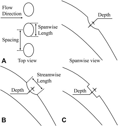
FIGURE 1. Dimple and groove geometry: (A) dimple; (B) U-groove; (C) rectangular groove.
The separation bubble on the Pak-B blade suction surface is investigated using large-eddy simulation in the present study. The large eddies which contain most of the turbulent kinetic energy (TKE) are calculated explicitly, while the smaller ones, which tend to be more isotropic and homogeneous, are modeled in LES. The Reynolds number based on the inlet velocity and axial chord length is 50,000. The freestream turbulence intensity is extremely low because the turbulence generators are not used at the inlet of the fluid domain. The schematic of the computational domain is shown in Figure 2. In order to eliminate the influence of inlet and outlet boundaries on the solution, the computational domain extended 1.0

FIGURE 2. Schematic of the computational domain.
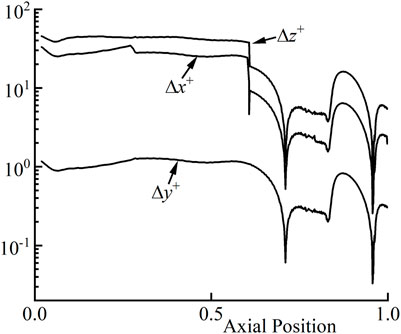
FIGURE 3. Grid resolution in wall units.
All simulations are performed using the RANS results as the initial conditions. The governing equations are closed using the WALE (wall-adapted local eddy-viscosity) sub-grid scale model, which has been extensively used in LES. The discretization of spatial derivatives is based on central differencing, and the implicit second-order accurate backward Euler integration is used to advance the solution in time. The total pressure and static pressure distributions specified on the inlet and outlet boundaries are related to the experimental values. The domain is bounded by a symmetric boundary condition in the spanwise direction. Only one single blade passage is calculated in pitch-wise, and the domain is bounded by a periodicity boundary condition. A no-slip wall condition is imposed on the blade surface. The time-step size in the simulations is
One of the challenges for numerical simulation in the LPT turbine is to predict the laminar separation bubble precisely. In Figure 4, the time- and spanwise-averaged static pressure coefficient (
where
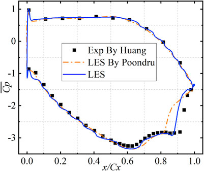
FIGURE 4. Time-averaged and spanwise-averaged wall-pressure coefficient distribution compared with experimental data by Huang and LES data by Poondru.
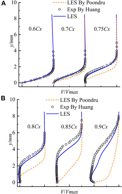
FIGURE 5. Time-averaged (A) and spanwise-averaged (B) boundary layer profiles compared with experimental data by Huang and LES data by Poondru.
In this section, the results calculated from the LES of separated boundary layers on the LPT blade surface for several passive control strategies: recessed dimples, recessed U-grooves, and recessed rectangular grooves, are carefully compared under investigated conditions. For the current investigation, these modified surface structures have the same axial position, maximum engraved depth, and almost the same width in the streamwise direction. A detailed analysis of recessed dimples based on the instantaneous flow structures and spectral analysis is then carried out to explore how the engraved dimples affect the boundary layer development on the LPT blade suction surface.
The time-averaged development of the boundary layer, which is obtained by calculating the arithmetic average of the results of nearly 3,000 time-steps, is discussed for different surface treatments. Figure 6 shows the contours of time-mean and spanwise-averaged streamwise velocity on spanwise vertical surfaces. Two spanwise vertical planes are selected on the dimpled surface for discussion: vertical plane located in the dimple center and dimple edge (between two dimples), which is represented as DC (dimple center) and DE (dimple edge). The reason for doing this is that dimples are 3D structures and have a different effect along the spanwise direction. Spanwise averaging has been done for the other cases to make the results more reliable. As shown in Figure 6, a large low-speed fluid region exists on the surface without modifications due to the severe separation of the boundary layer. When the surface is recessed by dimples, U-grooves, and rectangular grooves, the low-speed region of fluid is reduced significantly. Especially on the DC plane, the low-speed region is almost eliminated. In order to gain more details about the separation bubble, the predicted distribution on the aft portion of the suction surface of time- and spanwise-averaged wall-pressure coefficients and wall-skin friction coefficients,
where
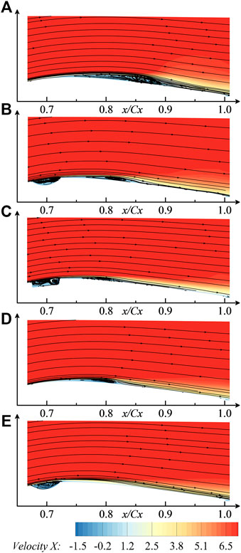
FIGURE 6. Contours of time- and spanwise-averaged streamwise velocity: (A) baseline; (B) U-groove; (C) rectangular groove; (D) DE plane; (E) DC plane.
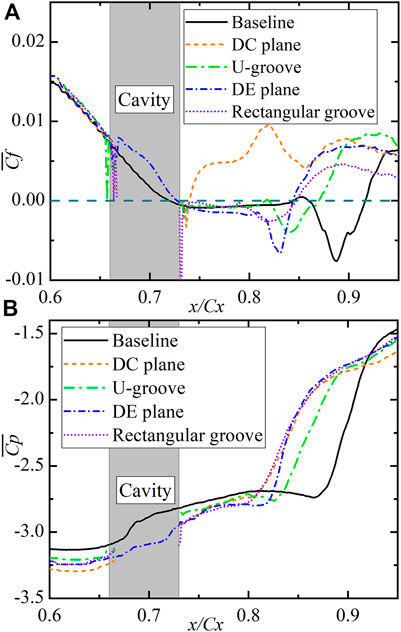
FIGURE 7. Time- and spanwise-averaged (A) wall-skin friction coefficient and (B) wall-pressure coefficient distribution for various surfaces.
The height of the separation bubble in the direction normal to the wall has changed differently from the bubble length along the streamwise direction. The streamwise variation of the displacement thickness,
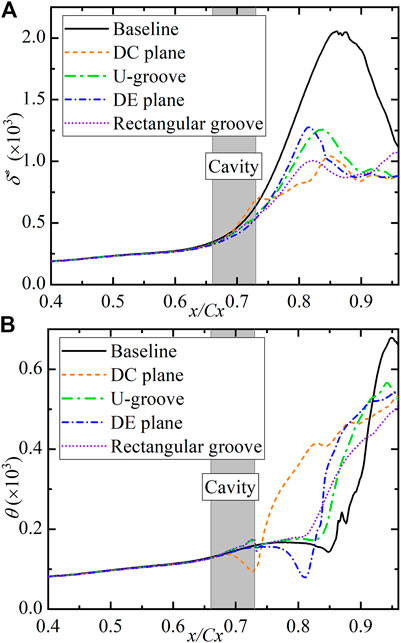
FIGURE 8. Time- and spanwise-averaged (A) displacement thickness and (B) momentum thickness distribution for various surfaces.
The displacement thickness varies slowly before separation and increases rapidly since the separation occurs. The surface without modification has the maximum value of displacement thickness, which indicates that the height of the separation bubble is the largest. All surface treatments significantly reduce the height of the separation bubble. However, the rectangular grooves and U-grooves are found to be more effective in reducing the thickness of the separation bubble compared to the dimples. The separation bubble on the surface recessed by rectangular grooves is much smaller in the direction normal to the surface than that on the DE plane, although the bubble is a little longer along the streamwise direction. A similar trend is obtained when the separation bubbles on the U-grooved and DE surfaces are compared. A serious mass deficit is observed although the boundary layer is attached to the DC plane, which might be caused by the thick boundary layer. The momentum thickness distribution in Figure 8B decreases first and then increases right downstream of the separation point. The decrease and rapid growth of
Furthermore, the transition process of the boundary layer plays a crucial role in the formation of a separation bubble. The shape factor H, which is plotted in Figure 9, is a useful parameter for empirically estimating the boundary layer’s state on separation and transition. It is calculated by the ratio of
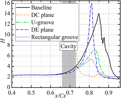
FIGURE 9. Time- and spanwise-averaged shape factor distribution for various surfaces.
Profile losses in a low-pressure turbine blade could be increased significantly due to the separation bubble. Figure 10 shows the variation of profile losses as the bubble length (BL) varies for different surface modifications. The loss coefficient used here is defined as
where
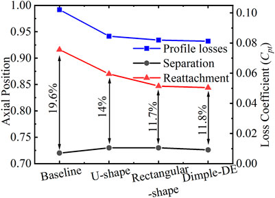
FIGURE 10. Separation bubble length and the correlated profile losses for various surfaces.
An overall understanding of the time-averaged development of the boundary layer has been obtained above. In this section, the spectral analysis is performed, and the instantaneous vortex structures inside the boundary layer are presented for discussion. The authors tried to get a detailed insight into the laminar–turbulent transition process to explain why these surface modifications can reduce the separation bubble size.
The rapid growth of disturbance inside the separated shear layer would lead to the laminar–turbulent transition, which is essential to the separation bubble size. Under low freestream turbulence conditions, inviscid Kelvin–Helmholtz (K-H) mode has been proved to be the dominant instability during the transition process of the separated boundary layers by numerous studies (Yang and Voke, 2001; Kurelek et al., 2016; McAuliffe and Yaras, 2007; Hosseinverdi and Fasel, 2019). With the growth of unstable fluctuations due to K-H instability, the shear layer rolls up, resulting in the formation of spanwise vortices (K-H vortices). The distortions and breakdown to small-scale turbulent structures of spanwise vortices then occur due to the small-scale turbulence activity (McAuliffe and Yaras, 2007). The Fourier spectra of the streamwise velocity fluctuations for all cases are presented in Figure 11 for several streamwise locations near the bubble. The data are obtained along with the separated shear layer where the large wall-normal velocity gradient exists. The related vortex structures are identified in Figure 12 by the pressure isocontours. For the unmodified surface, the boundary layer is laminar, and the inner disturbance is quite low at the locations before separation, as shown in Figure 11A. As the boundary layer develops, the disturbances are amplified, and a dominant frequency peak appears at around 1250 Hz, which represents the typical K-H instability frequency. This frequency could be confirmed through the Strouhal number,
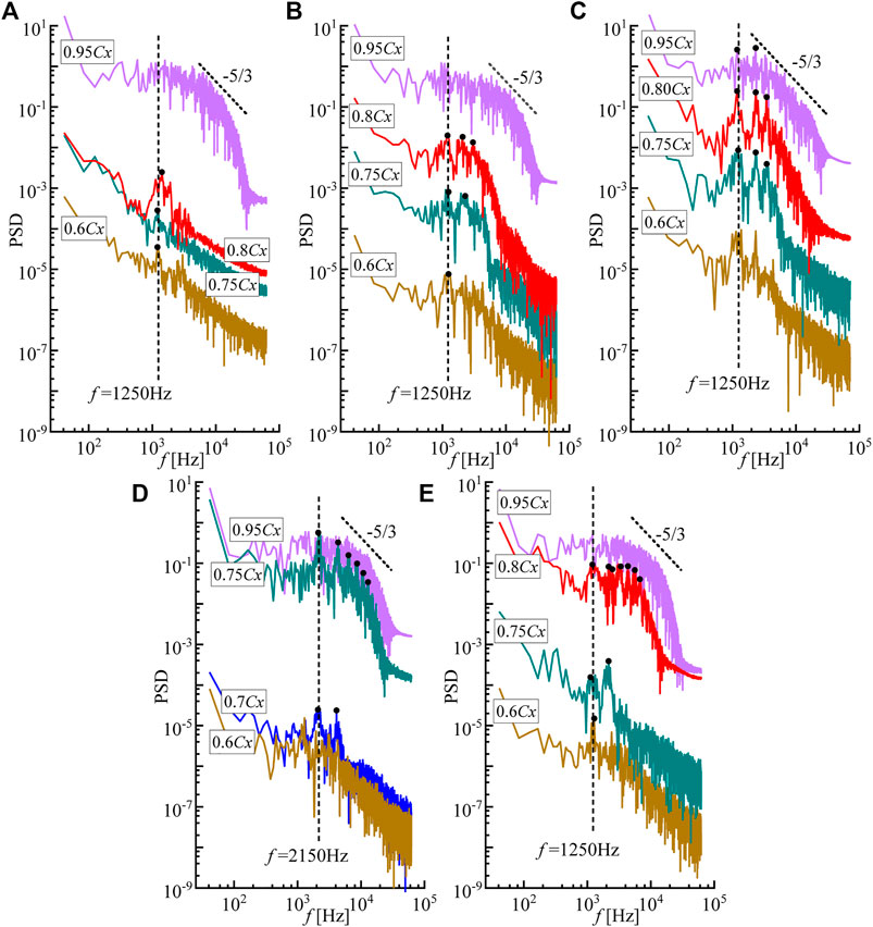
FIGURE 11. Power spectral of streamwise velocity fluctuations for all cases at various axial positions: (A) baseline; (B) U-shape; (C) rectangular shape; (D) DC plane; (E) DE plane.
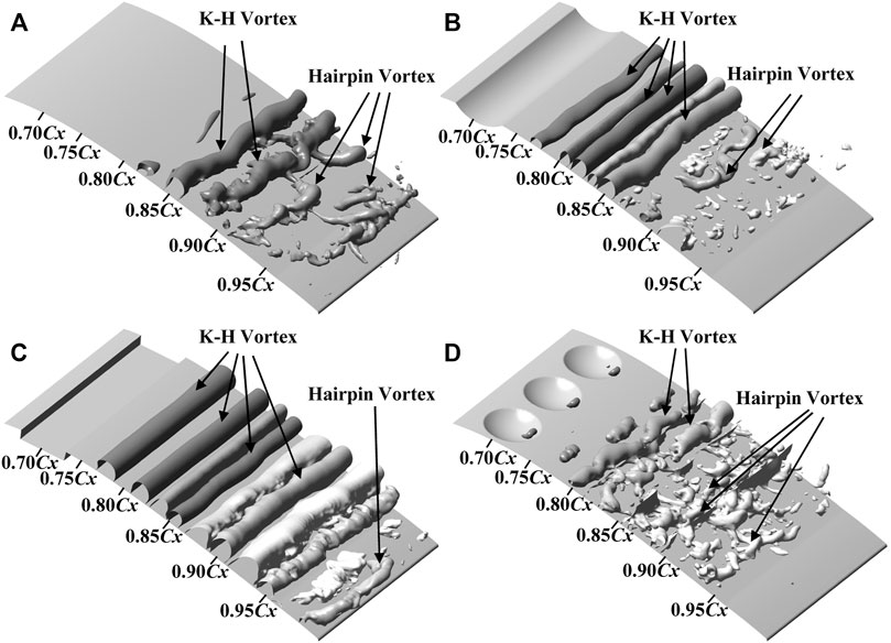
FIGURE 12. Vortex structures in the separation bubble identified by pressure iso-surfaces: (A) baseline; (B) U-shape; (C) rectangular shape; (D) dimple.
Growth of the most-amplified instability frequency results in the formation of spanwise quasi-two-dimensional vortices, as shown in Figure 12A. Further downstream, the spanwise vortices are distorted and break into turbulence very quickly over a short streamwise distance with the appearance of typical hairpin-like structures. Another evidence of the breakdown to turbulence is the frequency content redistribution over a much wider range, as observed in Figure 11A. The dominant frequency peak disappears, and fully developed turbulence has been established at 95% axial length position as confirmed by the classical spectrum slopes based on Kolmogorov’s theory for isotropic turbulence. Compared with the unmodified surface, the boundary layer becomes more unstable when it crosses over the surface of U-grooves and rectangular grooves, and the inner disturbance grows more rapidly, as shown in Figures 11B,C. The most-amplified fluctuation frequency occurs at the fundamental frequency 1,200 Hz, which is almost the same as the K-H instability frequency in the present study. As a result, the spanwise vortices roll up much earlier than on the unmodified surface, as shown in Figures 12B,C. However, the spanwise vortices have the intensified vortex intensity and exist over a much longer streamwise distance than on the smooth wall before the breakdown, which means the U-grooves and rectangular grooves have no significant effect in promoting the transition process. Especially, for the rectangular grooves, the spanwise vortices persist further downstream to 95% axial chord length due to a greater disturbance amplitude caused by the sharp edge. It can be concluded that the grooves lead to the stronger K-H instability waves, resulting in the earlier formation and shedding of spanwise vortices with intensified vortex intensity. The intensified spanwise vortices increase the momentum transfer process in the wall-normal direction, and a reattachment region exists downstream of the vortex. The shedding of spanwise vortices results in the periodic separation and reattachment of the boundary layer, and it shows a larger reattachment area in a time-averaged sense.
Nevertheless, the dimples show a completely different mechanism in reducing the laminar separation than the grooves. As shown in Figure 11D, PSD peaks at around the frequency of 2,150 Hz and at the subharmonic frequencies start to become visible at the 75% chord length location on the DC plane. The typical K-H instability frequency peak is not observed. Spectra of the streamwise velocity pertaining to the boundary layer on the DC plane indicate the existence of the high-frequency shedding vortices downstream of the dimple structure. The shedding vortices could also be identified in Figure 12D by the pressure isocontours. The boundary layer on the DC plane is almost attached in a time-averaged sense due to the high-frequency shedding vortices. On the DE plane, however, Figure 11E shows a dominant instability frequency at 1,166 Hz representing the typical instability frequency in the present study, which indicates the existence of the K-H vortices. As time proceeds further, disturbances in this frequency band are amplified, following a subharmonic growth. It is worth noting that another frequency peak appears near 2,100 Hz at 80% axial chord length. This could be the development of shedding vortices generated by the dimples along the spanwise direction, as shown in Figure 12D. The interaction between the higher-frequency shedding vortices and the low-frequency shedding K-H vortices results in a rapid breakdown of K-H vortices, causing an earlier transition of the laminar boundary layer into the turbulent one. Thus, the separation is inhibited significantly. The particularly three-dimensional structure of dimples makes it possible to promote the earlier boundary layer transition via a minor modification on the surface. The growth rate of most-amplified disturbances at various locations is also compared in Figure 13. The dimples lead to a lower level of disturbance than the others while the transition process is finished earlier. This may also be the reason why the dimples have a better performance at higher Reynolds numbers than the grooves.

FIGURE 13. Growth rate of most-amplified disturbances.
The different mechanisms between dimples, U-grooves, and rectangular grooves show the excellent performance of dimples in restraining the laminar flow separation under low freestream turbulence conditions. The following section describes the influence of several dimple parameters on the flow control effect and investigates the flow structures inside the dimple.
High-frequency shedding vortices downstream of the recessed dimples have been observed via the spectral analysis above. Due to the existence of front steps in the trailing edge of the cavities, the fluid flowing through the concave surfaces flows back into the cavities leading to the formation of vortices. However, unlike the U-grooves and rectangular grooves, the bending of dimple edge in the spanwise direction makes the vortex lean toward the streamwise direction. The fluid is accumulated from the spanwise sides to the dimple center, and a pair of counter-rotating streamwise vortices appear in the aft portion of the dimples. The dominant streamwise vortex pair is observed in the present study and many previous studies (Ligrani et al., 2001; Won et al., 2005). The temporal variation of the computed streamwise dimensionless vorticity distribution on the plane perpendicular to the flow direction near the trailing edge of the dimples is shown in Figure 14 for one whole period of the shedding vortices. It can be seen that a filling/dumping or “breathing” cycle similar to that described in Vincent and Mapple’s research (Vincent and Mapple, 2006) exists obviously inside the dimples. The intensity of the dominant streamwise vortex pair decreases and increases periodically, just like “breathing,” which is related to the shedding of vortices. The streamwise vortex pair becomes smaller with the shedding of vortices, as shown in Figure 14B. However, as time proceeds further, the small vortices generated at the downstream side of dimples gradually converge to the trailing edge of dimples. A new counter-rotating streamwise vortex pair appears at the trailing edge as presented in Figure 14C. These two pairs of streamwise vortices then merge into a stronger vortex pair, as shown in Figure 14A,D. In addition, the shedding vortex structures also have changed when they depart the dimple as shown in Figure 15. The dimensionless vorticity distribution on the plane downstream the dimples is presented in Figure 15 for a complete vortex shedding period. Two alternating streamwise vortex pairs (A and B) are observed in the figures. The stronger one, A, represents the shedding of dominant streamwise vortex pair, while the other indicates the shedding of vortex pairs induced by dominant vortices inside the dimples. Furthermore, the flow structures inside the dimples are significantly affected by the adverse pressure gradient since the dimples are placed behind the maximum velocity point on the suction side. More fluid flows back into the dimples, and the streamwise vortices inside the dimples are intensified. Meanwhile, the two counter-rotating vortices coalesce on the dimple trailing edge, and a small scale of spanwise vortex appears at the dimple center as shown in Figure 12D. The spanwise vortex connects the streamwise vortex pair: A and B, forming a shedding structure. The shedding structures are associated with the adverse pressure gradient closely. The existence of the adverse pressure gradient makes the streamwise vortex pair B be deflected to the spanwise direction gradually and finally interacts with the spanwise vortices rolled up on both sides.
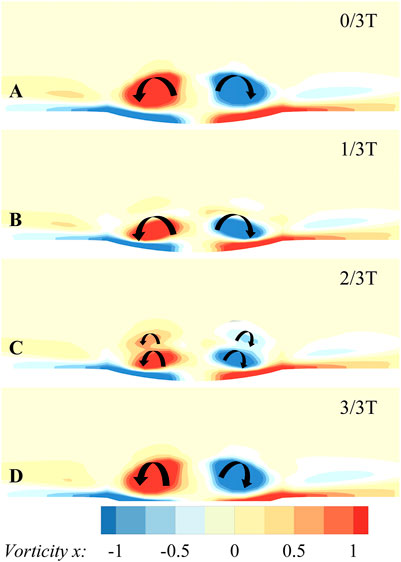
FIGURE 14. Streamwise vorticity contours at the dimple trailing edge during one shedding periodicity.

FIGURE 15. Streamwise vorticity contours downstream the dimple trailing edge in one cycle of vortex shedding.
The boundary layer developments on the blade suction surfaces modified by the recessed dimples, recessed U-grooves, and recessed rectangular grooves have been investigated through large-eddy simulation under low Reynolds number and low freestream turbulence conditions. The mechanisms of grooves and dimples associated with the inhibition of laminar separation are demonstrated in the present study.
The dimples show the best performance in reducing profile losses by restraining the separation bubble size. The overall profile losses are reduced by 20.4% with dimples, 18.9% with rectangular grooves, and 16.2% with U-grooves. Under low freestream turbulence conditions, the transition process in a separation bubble is dominated by Kelvin–Helmholtz instability, which results in the formation of spanwise vortices. The spanwise vortices are then distorted and broken into fully turbulent structures. Grooves and dimples show different mechanisms for restraining the separation bubble size. Stronger K-H vortices are induced by grooves of U-shape and rectangular shape, resulting in a larger reattachment area downstream the vortex. However, the intensified spanwise vortices are more difficult to break down to turbulence. As for the rectangular grooves, the turbulent boundary layer is fully established near the trailing edge. A high-speed shedding vortex has been observed downstream the dimple center with a shedding frequency twice the K-H instability frequency through the spectral analysis and pressure isocontour. The interaction between high-speed shedding vortices and spanwise vortices leads to an earlier breakdown to turbulence with a lower level of disturbances. The earlier transition makes the separated boundary layer reattach further upstream, thus reducing the profile losses. The lower level of disturbances caused by dimples also makes the persistent high performance of LPT at a higher Reynolds number possible.
Furthermore, the dimples require a minor surface treatment on the blade surface than the grooves. It could be concluded that dimples have the greatest potential than the grooves in reducing the profile losses due to the unique 3D structures. This study provides further insight into why dimples are better than grooves as a flow control technology in low-pressure turbine blades, and it is meaningful for the development of new passive flow control technologies.
The flow structures inside the dimples are also investigated. A dominant counter-rotating streamwise vortex pair forms in the aft portion of the dimple. When subjected to an adverse pressure gradient, the flow structure inside the dimple is significantly different from that under the condition of the positive pressure gradient. The dominant counter-rotating vortices coalesce at the dimple trailing edge and then shed from the dimples alternatively with another pair of counter-rotating vortices induced by itself. The streamwise vortices then deflect in the spanwise direction and finally interact with the spanwise vortices.
The raw data supporting the conclusions of this article will be made available by the authors, without undue reservation.
PY and SC pushed forward this research topic and were responsible for manuscript writing. WL contributed to the numerical simulation. CZ provided significant help in data processing.
This work is supported by the National Natural Science Foundation of China (Grant Nos. 52076052 and 51776048) and National Science and Technology Major Project of China (Grant Nos. Y2019-VIII-0013-0174).
The authors declare that the research was conducted in the absence of any commercial or financial relationships that could be construed as a potential conflict of interest.
All claims expressed in this article are solely those of the authors and do not necessarily represent those of their affiliated organizations, or those of the publisher, the editors, and the reviewers. Any product that may be evaluated in this article, or claim that may be made by its manufacturer, is not guaranteed or endorsed by the publisher.
Bearman, P. W., and Harvey, J. K. (1976). Golf ball Aerodynamics. Aeronaut. Q. 27 (2), 112–122. doi:10.1017/s0001925900007617
Casey, J., King, P., and Sondergaard, R. (2004). “Parameterization of Boundary Layer Control Dimples on a Low Pressure Turbine Blade,” in 40th AIAA/ASME/SAE/ASEE Joint Propulsion Conference and Exhibit. Fort Lauderdale, Florida: American Institute of Aeronautics and Astronautics, 3570. doi:10.2514/6.2004-3570
Cui, J., Nagabhushana Rao, V., and Tucker, P. (2016). Numerical Investigation of Contrasting Flow Physics in Different Zones of a High-Lift Low-Pressure Turbine Blade. J. Turbomach. 138 (1), 011003. doi:10.1115/1.4031561
Hosseinverdi, S., and Fasel, H. F. (2019). Numerical Investigation of Laminar-Turbulent Transition in Laminar Separation Bubbles: the Effect of Free-Stream Turbulence. J. Fluid Mech. 858, 714–759. doi:10.1017/jfm.2018.809
Houtermans, R. G., Coton, T., and Arts, T. (2004). Aerodynamic Performance of a Very High Lift Low Pressure Turbine Blade with Emphasis on Separation Prediction. J. Turbomach. 126 (3), 406–413. doi:10.1115/1.1748416
Huang, J. (2005). Separation Control over Low Pressure Turbine Blades Using Plasma Actuators. South Bend, Indiana: University of Notre Dame. [dissertation]. [South Bend].
Hwang, S. D., Kwon, H. G., and Cho, H. H. (2008). Heat Transfer with Dimple/protrusion Arrays in a Rectangular Duct with a Low Reynolds Number Range. Int. J. Heat Fluid Flow 29 (4), 916–926. doi:10.1016/j.ijheatfluidflow.2008.01.004
Ji, Z., Qin, J., Cheng, K., Liu, H., Zhang, S., and Dong, P. (2021). Design and Performance of a Compact Air-Breathing Jet Hybrid-Electric Engine Coupled with Solid Oxide Fuel Cells. Front. Energ. Res. 402. doi:10.3389/fenrg.2020.613205
Kurelek, J. W., Lambert, A. R., and Yarusevych, S. (2016). Coherent Structures in the Transition Process of a Laminar Separation Bubble. AIAA J. 54 (8), 2295–2309. doi:10.2514/1.j054820
Lake, J., King, P., and Rivir, R. (2000). “Low Reynolds Number Loss Reduction on Turbine Blades with Dimples and V-Grooves,” in 38th Aerospace Sciences Meeting and Exhibit. Reston, Virginia: American Institute of Aeronautics and Astronautics, 738. doi:10.2514/6.2000-738
Lake, J., King, P., and Rivir, R. (1999). “Reduction of Separation Losses on a Turbine Blade with Low Reynolds Numbers,” in 37th Aerospace Sciences Meeting and Exhibit. Reston, Virginia: American Institute of Aeronautics and Astronautics, 242. doi:10.2514/6.1999-242
Ligrani, P. M., Harrison, J. L., Mahmmod, G. I., and Hill, M. L. (2001). Flow Structure Due to Dimple Depressions on a Channel Surface. Phys. Fluids 13 (11), 3442–3451. doi:10.1063/1.1404139
Lyall, M. E., King, P. I., Sondergaard, R., Clark, J. P., and McQuilling, M. W. (2011). An Investigation of reynolds Lapse Rate for Highly Loaded Low Pressure Turbine Airfoils with Forward and Aft Loading. Turbo Expo. Power Land, Sea, Air 54679, 865–876. doi:10.1115/gt2011-46328
Mahallati, A., McAuliffe, B. R., Sjolander, S. A., and Praisner, T. J. (2013). Aerodynamics of a Low-Pressure Turbine Airfoil at Low Reynolds Numbers—Part I: Steady Flow Measurements. J. Turbomach. 135 (1). doi:10.1115/1.4006319
McAuliffe, B. R., and Yaras, M. I. (2005). Separation-bubble-transition Measurements on a Low-Re Airfoil Using Particle Image Velocimetry. Turbo Expo. Power Land, Sea, Air 47268, 1029–1038. doi:10.1115/gt2005-68663
McAuliffe, B. R., and Yaras, M. I. (2007). Transition Mechanisms in Separation Bubbles under Low and Elevated Freestream Turbulence. Turbo Expo. Power Land, Sea, Air 47934, 1063–1076. doi:10.1115/gt2007-27605
Montis, M., Niehuis, R., and Fiala, A. (2011). Aerodynamic Measurements on a Low Pressure Turbine cascade with Different Levels of Distributed Roughness. Turbo Expo. Power Land, Sea, Air 54679, 457–467. doi:10.1115/gt2011-45015
Poondru, S. (2008). Large-Eddy Simulation and Active Flow Control of Low-Reynolds Number Flow through a Low-Pressure Turbine Cascade. Cincinnati, Ohio: University of Cincinnati. [dissertation].
Praisner, T. J., Grover, E. A., Knezevici, D. C., Popovic, I., Sjolander, S. A., Clark, J. P., et al. (2008). Toward the Expansion of Low-Pressure-Turbine Airfoil Design Space. Turbo Expo. Power Land, Sea, Air 43161, 1323–1331. doi:10.1115/gt2008-50898
Rizzetta, D., and Visbal, M. (2003). “Numerical Investigation of Transitional Flow through a Low-Pressure Turbine cascade,” in 33th AIAA Fluid Dynamics Conference and Exhibit. Orlando, Florida: American Institute of Aeronautics and Astronautics, 3587. doi:10.2514/6.2003-3587
Robarge, T., Stark, A., Min, S. K., Khalatov, A., and Byerley, A. (2004). “Design Considerations for Using Indented Surface Treatments to Control Boundary Layer Separation,” in 42th AIAA Aerospace Sciences Meeting and Exhibit. Reno, Nevada: American Institute of Aeronautics and Astronautics, 425. doi:10.2514/6.2004-425
Roberts, S. K., and Yaras, M. I. (2005). Large-eddy Simulation of Transition in a Separation Bubble. Turbo Expo. Power Land, Sea, Air 47268, 1049–1055. doi:10.1115/gt2005-68666
Rouser, K. P. (2002). Use of Dimples to Suppress Boundary Layer Separation on a Low Pressure Turbine Blade. Ohio: Wright-Patterson Air Force Base. [master’s thesis]..
Sondergaard, R. (2008). “LPT Flow Control at AFRL,” in 38th Fluid Dynamics Conference and Exhibit. Seattle, Washington: American Institute of Aeronautics and Astronautics, 4156. doi:10.2514/6.2008-4156
Talan, M., and Hourmouziadis, J. (2002). Characteristic Regimes of Transitional Separation Bubbles in Unsteady Flow. Flow, turbulence and combustion 69 (3), 207–227. doi:10.1023/A:1027355105017
Vincent, R., and Mapple, R. (2006). “CFD Investigation of Laminar Flow over a Dimpled Surface Indentation,” in 36th AIAA Fluid Dynamics Conference and Exhibit. San Francisco, California: American Institute of Aeronautics and Astronautics, 3912. doi:10.2514/6.2006-3912
Volino, R. J. (2003). Passive Flow Control on Low-Pressure Turbine Airfoils. J. Turbomach. 125 (4), 754–764. doi:10.1115/1.1626685
Volino, R. J. (2008). Separated Flow Measurements on a Highly Loaded Low-Pressure Turbine Airfoil. Turbo Expo. Power Land, Sea, Air 43161, 1427–1437. doi:10.1115/gt2008-51445
Won, S. Y., Zhang, Q., and Ligrani, P. M. (2005). Comparisons of Flow Structure above Dimpled Surfaces with Different Dimple Depths in a Channel. Phys. Fluids 17 (4), 045105. doi:10.1063/1.1872073
Yang, Z., and Voke, P. R. (2001). Large-eddy Simulation of Boundary-Layer Separation and Transition at a Change of Surface Curvature. J. Fluid Mech. 439, 305–333. doi:10.1017/s0022112001004633
Keywords: dimple, low-pressure turbine, laminar separation, spectral analysis, flow control, LES
Citation: Yang P, Chen S, Li W and Zeng C (2022) Large-Eddy Simulation of the Boundary Layer Development in a Low-Pressure Turbine Cascade With Passive Flow Control. Front. Energy Res. 10:853166. doi: 10.3389/fenrg.2022.853166
Received: 12 January 2022; Accepted: 01 March 2022;
Published: 22 March 2022.
Edited by:
Xiao Liu, Harbin Engineering University, ChinaReviewed by:
Shaobing Han, Dalian Maritime University, ChinaCopyright © 2022 Yang, Chen, Li and Zeng. This is an open-access article distributed under the terms of the Creative Commons Attribution License (CC BY). The use, distribution or reproduction in other forums is permitted, provided the original author(s) and the copyright owner(s) are credited and that the original publication in this journal is cited, in accordance with accepted academic practice. No use, distribution or reproduction is permitted which does not comply with these terms.
*Correspondence: Shaowen Chen, Y3N3ZW1haWxAaGl0LmVkdS5jbg==
Disclaimer: All claims expressed in this article are solely those of the authors and do not necessarily represent those of their affiliated organizations, or those of the publisher, the editors and the reviewers. Any product that may be evaluated in this article or claim that may be made by its manufacturer is not guaranteed or endorsed by the publisher.
Research integrity at Frontiers
Learn more about the work of our research integrity team to safeguard the quality of each article we publish.