- 1Guangzhou Power Supply Bureau of Guangdong Power Grid Co., Guangzhou, China
- 2NR Electric Co., Ltd., Nanjing, China
The VSC-HVDC system can damp the inter-area low-frequency oscillation effectively. To enhance the ability of the VSC-HVDC supplementary control, this article proposes a unified low-frequency oscillation controller design using the robustness theory. The unified control strategy uses both the active power control and reactive power control loop of the VSC to expand the supplementary control dimensions. To design the controller, the TLS-ESPRIT identification method is used to obtain the system small signal model and the oscillation characteristic. Based on the model identified out, the linear matrix inequality method based robust control theory is applied for the controller design, and the robust controllers for active power control and reactive power control loop are both designed to improve the control effect. Finally, the simulation results show that the controller can reach better control effect and the robustness can also be guaranteed.
1 Introduction
Power grid interconnection is an inevitable trend in the development of the power industry (Tao et al., 2021a). Large-scale interconnected power grids can reduce the total reserve capacity of the entire power grid, and it also can use the time difference and seasonal difference in different regions to ease the fluctuation of load peaks and valleys. The power resources can be used reasonably and economically, and the cost can also be reduced greatly (Tao et al., 2021b).
Although the large-scale AC–DC hybrid transmission system can provide powerful transmission capacity and flexible operation modes, many new problems will be brought to the power grid. The weakly damped low-frequency oscillation (LFO) problem is one of the typical challenges faced by large-scale grid interconnection. The power system stabilizer (PSS) is the most convenient method to suppress low-frequency oscillation, and a lot of researchers use intelligent methods to improve PSS’s performance. For example, Abido (2002) proposes a novel evolutionary algorithm-based approach to the optimal design of multimachine power system stabilizers (PSSs), the proposed approach employs a particle swarm optimization (PSO) technique to search for optimal settings of PSS parameters. Abdel-Magid and Abido (2003) uses the optimal multi-objective design of robust multimachine power system stabilizers (PSSs) based on genetic algorithms, where the problem of robustly selecting the parameters of the power system stabilizers is converted to an optimization problem, which is solved by a genetic algorithm with the eigenvalue-based multi-objective function. Cai and Erlich (2005) also studied the simultaneously coordinated tuning of the flexible AC transmission systems (FACTS) power oscillation damping controller and the conventional power system stabilizer (PSS) controllers in multimachine power systems, and the parameter-constrained nonlinear optimization algorithm is used.
It is found that PSS mainly performs additional control on generators, so it has a good control effect and the lowest cost for intra-regional oscillations, but for inter-regional oscillations, its effect is poor, especially in the design of stabilizers in a multimachine system (Wang et al., 2020). With the development of HVDC technology, additional damping control of line-commutated converter-based high-voltage direct current (LCC-HVDC) transmission systems becomes a unique resource in AC–DC hybrid grids and can suppress the inter-regional oscillations effectively (Jiang et al., 2019). Smed and Andersson (1993) damps the oscillations with power modulation of LCC-HVDC links, showing that active power modulation is efficient when applied a short mass-scaled electrical distance from one of the swinging machines. Pirooz Azad et al. (2013) studies the supplementary damping control-based LCC converters’ constant current control mode, and the WAS concept is used to damp the oscillation and the predictive control theory is also studied in this article. Li et al. (2012) proposed a coordination approach for the controller design of HVDC and flexible ac transmission systems (FACTS) wide-area controls, which is realized with one HVDC interconnected transmission.
It can be seen that LCC-HVDC are widely used for supplementary damping. But compared with the voltage-sourced converter-based (VSC) HVDC, the LCC-HVDC is usually suffered from the commutation failure problem (Zhang, 2021). So, some people start designing the supplementary damping control through the VSC-HVDC system. Fuchs et al. (2014) demonstrates the stabilization of large power systems using VSC-HVDC links, and the performance enhancement obtained with a global MPC-based grid damping controller is verified. Preece et al. (2013) does the research similar to Pirooz Azad et al. (2013), where the additional controller is added in the VSC system, and to damp the inter-area oscillations, the MLQG method is used to improve the controller’s performance. Huang et al. (2019) also investigates how virtual synchronous machines affect LFOs in power systems. Although some studies related to supplementary damping control have been carried out in the VSC-HVDC area, the controller’s robustness is not specially considered. Moreover, most of the damping controls are implemented through the active power control loop, and the reactive controller is neither considered usually.
To design the supplementary damping control based on the active and reactive control loop through the VSC-HVDC system, and to guarantee the controller’s robustness, this study proposes a unified VSC-HVDC supplementary control strategy. The novelty of this study can be concluded from two aspects. The first novelty is that the reactive and active power control channels of VSC are both used to suppress the oscillations, which has better effect for system stability enhancement; the second novelty of this study is that the robust control theory is applied for the LFO controller design, which can guarantee the correctness of the controller in different situation.
The article is organized as that Section 2 introduces the VSC-HVDC structure and unified supplementary control scheme. Section 3 describes the system modeling method using TLS-ESPRIT identification technology. Based on the obtained small signal model, Section 4 designed the unified controller using mixed H2/H∞ robust control theory based on the LMI approach. Section 5 studies the cases, and Section 6 makes the conclusions.
2 The VSC-HVDC Structure and Unified Supplementary Control
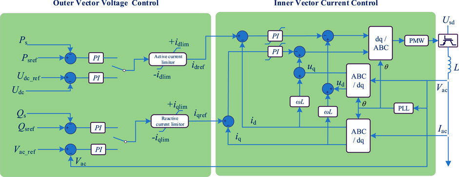
The structure of a VSC-HVDC system with d-q control scheme is presented as in Figure 1. The control of VSC can be divided into two parts, namely, the outer vector voltage control and the inner vector current control.
2.1 Outer Vector Voltage Control Loop
According to Figure 1, the outer vector voltage control is composed of two parts. The first part outputs the active current reference idref, while the second part outputs the reactive current reference iqref, and the idref is decided by the deviation of the active power Ps and its reference PSref, or by the deviation of the DC voltage Udc and its reference Udc_ref. Similarly, the iqref is decided by the deviation of the reactive power Qs and its reference QSref, or by the deviation of the AC voltage Vac and its reference Vac_ref.
Generally, for a multi-terminal VSC-HVDC system, there is always a converter in constant DC voltage control mode. So, the supplementary damping control should be added at the converter in constant active power control. The chosen converter’s outer vector controls are presented in the following Figure 2.
2.2 The Inner Vector Current Control Loop
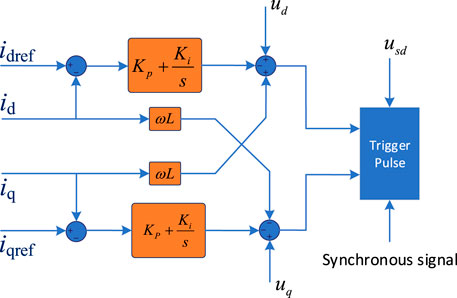
Figure 3 shows the inner control loop, which is presented as follows.
The model of VSC-HVDC in d-q coordinates can be expressed as shown in (1)–(3), and the definitions of the variables in the equations can be found in Li et al. (2017).
2.3 The Unified Supplementary Damping Control for VSC
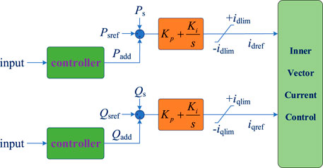
It can be seen from the earlier description that the main control of the VSC decides its active and reactive power. So, to realize the damping control for the AC system, the supplementary control is needed besides main control. For a converter in constant power control, the supplementary control is usually added at its active power control loop. Specifically, the outer vector current control is used for extra control function. It is known that the active power mainly decides the damping characteristic, so the supplementary damping control of VSC can be designed at the constant active power control loop. On the other side, although the reactive power has less impact on the frequency oscillation, the influence cannot be ignored. As the reactive power control can change the voltage characteristic, which can also improve the damping performance of the power grid.
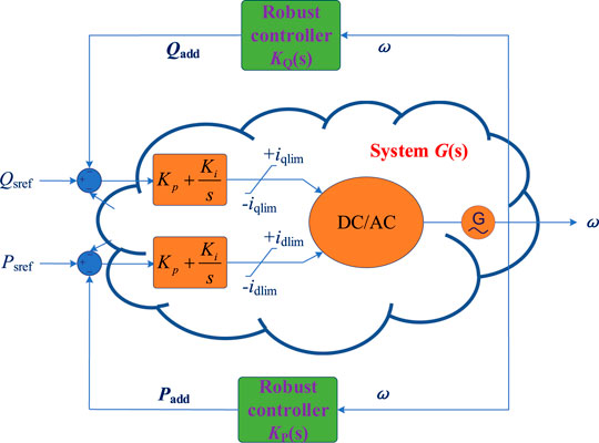
Considering the active power control and the reactive power of the VSC are decoupled by the d-q control scheme, another reactive supplementary damping control can also be designed at the reactive outer vector control loop. With such a design, the damping control abilities of the VSC can be enhanced, and the control dimensions can also be expanded from only one to two channels. Such a control concept can be defined as a unified supplementary damping control scheme, as it utilizes the apparent capacity of a single VSC converter. The control diagrams of a unified supplementary damping control are presented in Figure 4.
3 System Modeling Through TLS-ESPRIT Identification
3.1 The System Modeling Method
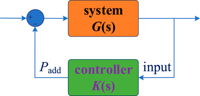
It is known that before the controller design, the controlled system should be confirmed, as shown in Figure 5. In this article, the controller system is the hybrid AC-DC system, as the low-frequency oscillation always occurs in the large-scale connected power grid. So, after introducing the supplementary control of VSC, the key problem now is how to establish the system model.
To establish the power grid system model, the classical method is to model every single component and device such that the most accurate characteristics can be reflected. However, the scale of the modern power system is very large, and such a method can hardly be used for practical engineering. Another important and widely used method is to identify the system without modeling the specific components. This method is suitable for small signal analysis, and the TLS-ESPRIT identification algorithm is used in this article.
3.2 The TLS-ESPRIT Identification Algorithm
The total least square estimation of signal parameters via rotational invariance techniques (TLS-ESPRIT) algorithm is an effective tool for harmonic analysis and attenuated sinusoidal signal parameter estimation (Tripathy et al., 2011), (Bachl, 1995). Compared with traditional algorithm simulation, it has the characteristics of strong antinoise and interference ability. It has been widely used in voice signals, biological signal processing, and other occasions.
The core idea of the ESPRIT algorithm is to calculate the rotation operator of the signal through the autocorrelation matrix and the cross-correlation matrix formed by the data to obtain the frequency and attenuation factor of the signal through the rotation recognition, and then combine the TLS separation to obtain the amplitude and phase of the signal.
Generally, the sampled signal can be expressed as a series of combinations of sinusoidal signals and noise, whose amplitude decays exponentially. The expression at the sampling moment can be expressed as follows:
where
Such that the Hankle matrix is formed from the sampled data as Equation 5 shows, in which L > P, M > P, L + M - 1 = N.
By performing the singular value decomposition of the aforementioned matrix using Equation 6
In Equation 6, V H represents the conjugate transpose of the matrix V, M is a diagonal matrix, and the diagonal elements of the M are the singular values arranged in accordance with the size. The V is divided into signal subspace VS and noise subspace VN according to the size of the singular value. The column vector of VS is the eigenvector corresponding to the largest singular values P of the matrix X.
By deleting the first and second rows of VS the remaining matrices are V1 and V2. When noise and interference are not considered, there exist an invertible matrix Ψ, which makes
Considering the noise interference, Equation 7 can be rewritten as follows:
According to Ψ, the signal parameters can be obtained, such that the TLS method is used to optimize Ψ and minimize the norm of the error matrix
where
Finally, by calculating the eigenvalues
For a N point sampling signal Y = λc, where
Such that, by using the least square method to obtain the solution of the equation
4 Mixed H2/H∞ Robust Control Based on the LMI Approach
After the system modeling, the next step is to design damping controllers with satisfied performance. The mixed synthesis with regional pole placement is employed in this article (Chilali et al., 1999; Lien, 2004).
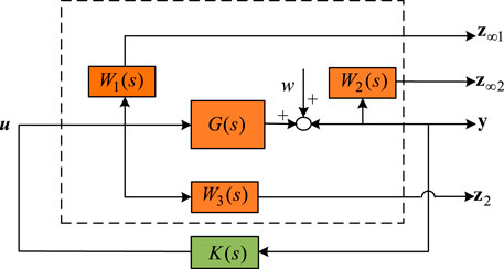
Figure 6 shows the robust control diagrams with consideration of an identified system G(s) using TLS-ESPRIT technology, and the definition of each part can be found in Chilali et al. (1999) and Lien (2004).
Let z∞ = [ z∞, z∞2 ]T, Equation 19 shows the state space of the controlled system.
The controller K(s) is written as follows:
The whole system under control can be given as follows:
where
The controllers considering H∞, H2, and damping performance should satisfy the following equations, the meanings and definitions of the equations and the variables can be found in Zeng and Li( 2018). Figure 7 shows the damping performance with satisfied damping ratios under the constrains of these equations.
Finally, by combining the TLS-ESPRIT identification algorithm, the whole unified robust control scheme based on the LMI method both considering the robustness, controllability, and damping performances can be presented as in Figure 8.
5 Case Study
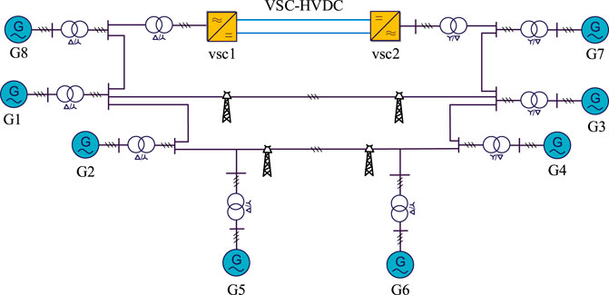
To verify the aforementioned analysis, the simulations are implemented in this section. The structure of an AC–DC hybrid system to be studied is shown in Figure 9. The system is an eight-machine two-area system, where VSC-HVDC and the AC lines connect two areas together. The detailed parameters of VSC-HVDC can be found in.
5.1 Control Signals Selection and System Identification
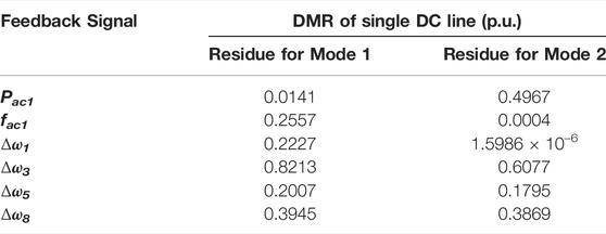
To realize the system control, the feedback signals should be selected at first. In this article the residue index is used for signal selection. Let a single input single output system’s state space equation is given as follows:
where a is the state matrix,
where
The transfer function of Eq. 1 can be written as follows:
where
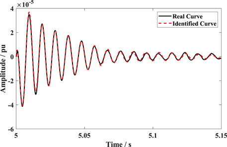
To design the unified robust controller of the previously mentioned system, the identification work should be performed at first. According to the analysis, the feedback signal of the robust controller is chosen as ω3, which is the rotor speed of G3. The transfer function of the identified system for active power control loop is given as in (30). The comparison between the real curve and the identified curve is presented as Figure 10, it can be seen that the two curves match well with each other, which prove the correctness of the TLS-ESPRIT algorithm.
Similarly, the transfer function of the identified system for reactive power control loop is given as in (31). The comparison between the real curve and the identified curve is presented as Figure 11, it also can be seen that the two curves match well with each other, which further prove the correctness of the TLS-ESPRIT algorithm.
5.2 Robust Controller Design
The weight function of the robust controller is given as follows:
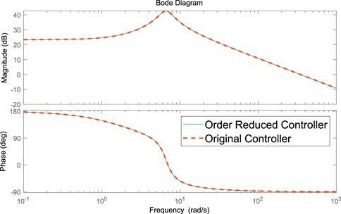
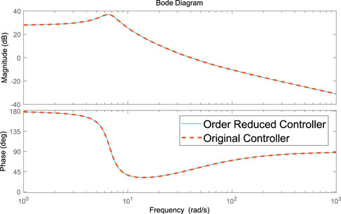
The order-reduced robust controllers of the active and reactive power control loop are shown in (32) and (33), respectively, and the bode diagrams of each controller before and after order reducing are also shown in Figure 12 and Figure 13, respectively.
5.3 Simulation Verification
Then the unified robust controllers are added into the system as shown in Figure 9, and the control effects with only active supplementary control is also presented in each simulation cases to validate the unified robust controllers’ effect and advantages.
5.3.1 In Load Disturbance Occasion
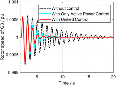
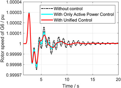
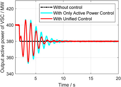
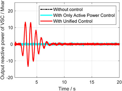
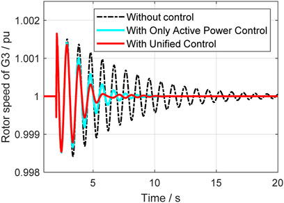
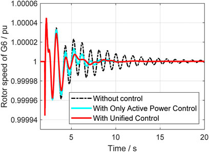
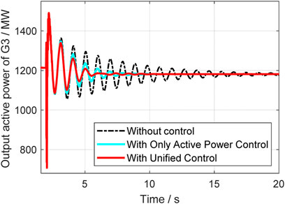
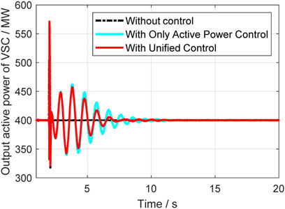
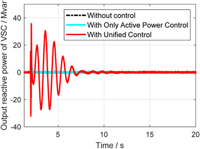
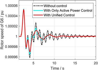
In this case, a relatively small disturbance is implemented at the vsc2 side. At 2s, the load at vsc2 suddenly reduced, and the system’s operation situations are compared in different control strategies. Figure 14 to Figure 18 give out the rotor speeds, active power, and reactive power of generators and VSC-HVDC.
From Figures 14–16, it can be seen that the unified control has much better effect and the damping ration can be enhanced a lot. Compared with the classical active power controller, the unified control can further improve the system small stability, and it further proves that the reactive power control can help with damping enhancement. The active and reactive power output of VSC are also given in Figures 17, 18, where it indicates that unified controller can control the damping from two dimensions and is very helpful. Table 2 gives the specific damping ratio changing situations to present the effect more clearly.
5.3.2 In Fault Occasion
In this case, a single phase to ground fault occurs at 2s, and the system’s operation situations are compared in different control strategies. Figure 19–Figure 23 give out the comparison results. It also proves the effectiveness and correctness of the unified controller.
5.3.3 In Operation Mode Changes Occasion
To further prove the robustness of the proposed method, the operation mode of the VSC is changed at 2 s, that is the output of the VSC is reduced from the rated 400–50 MW, and the system’s operation situations are compared in different control strategies. Figure 24–Figure 28 give out the comparison results. It proves the unified controller can still damp the oscillations and thus the robustness of the unified controller can be validated.
6 Conclusion
This article studies the unified supplementary damping controller to suppress low-frequency oscillation through VSC-HVDC and the following conclusions can be obtained. The active and reactive power control loop of VSC can be both used for oscillation control, and the reactive supplementary damping controller is independent with the classical active damping controller due to VSC’s decoupled d-q control scheme, which expands the control dimensions of VSC-HVDC for LFO control. Compared with the classical active power damping controller, suppressing the low-frequency oscillation through VSC can have a better effect. Because there are actually two controllers that damp the oscillation simultaneously, and the damping ratio of the original oscillation modes can both be increased when the controllers are added. The LFO can both be quickly eliminated whether it is in fault, power disturbance, and operation vary occasions.
Data Availability Statement
The original contributions presented in the study are included in the article/Supplementary Material; further inquiries can be directed to the corresponding author.
Author Contributions
ZJ: conceptualization, writing—original draft, and writing—review and editing. ZY: software and data curation. WF: writing—review and editing. YJ: writing—original draft and writing—review and editing. WJ: writing—review and editing.
Conflict of Interest
Authors ZJ, ZY, YJ and WJ were employed by Guangzhou Power Supply Bureau of Guangdong Power Grid Co. Author WF was employed by NR Electric Co., Ltd.
Publisher’s Note
All claims expressed in this article are solely those of the authors and do not necessarily represent those of their affiliated organizations, or those of the publisher, the editors, and the reviewers. Any product that may be evaluated in this article, or claim that may be made by its manufacturer, is not guaranteed or endorsed by the publisher.
Supplementary Material
The Supplementary Material for this article can be found online at: https://www.frontiersin.org/articles/10.3389/fenrg.2022.851362/full#supplementary-material
References
Abdel-Magid, Y. L., and Abido, M. A. (2003). Optimal Multiobjective Design of Robust Power System Stabilizers Using Genetic Algorithms. IEEE Trans. Power Syst. 18 (3), 1125–1132. doi:10.1109/TPWRS.2003.814848
Abido, M. A. (2002). Optimal Design of Power-System Stabilizers Using Particle Swarm Optimization. IEEE Trans. Energ. Convers. 17 (3), 406–413. doi:10.1109/TEC.2002.801992
Bachl, R. (1995). The Forward-Backward Averaging Technique Applied to TLS-ESPRIT Processing. IEEE Trans. Signal. Process. 43 (11), 2691–2699. doi:10.1109/78.482118
Cai, L. J., and Erlich, I. (2005). Simultaneous Coordinated Tuning of PSS and FACTS Damping Controllers in Large Power Systems. IEEE Trans. Power Syst. 20 (1), 294–300. doi:10.1109/TPWRS.2004.841177
Chilali, M., Gahinet, P., and Apkarian, P. (1999). Robust Pole Placement in LMI Regions. IEEE Trans. Automat. Contr. 44 (12), 2257–2270. doi:10.1109/9.811208
Fuchs, A., Imhof, M., Demiray, T., and Morari, M. (2014). Stabilization of Large Power Systems Using VSC-HVDC and Model Predictive Control. IEEE Trans. Power Deliv. 29 (1), 480–488. doi:10.1109/TPWRD.2013.2280467
Huang, L., Xin, H., and Wang, Z. (2019). Damping Low-Frequency Oscillations Through VSC-HVdc Stations Operated as Virtual Synchronous Machines. IEEE Trans. Power Electron. 34 (6), 5803–5818. doi:10.1109/TPEL.2018.2866523
Jiang, Q., Li, B., and Liu, T. (2019). Large-Scale Power Base's Impact on Low Frequency Oscillation Characteristic in UHVAC Power Transmission System. IEEE Access 7, 56423–56430. doi:10.1109/ACCESS.2019.2913663
Li, B., Liu, T., and Zhang, Y. (2017). Unified Adaptive Droop Control Design Based on Dynamic Reactive Power Limiter in VSC-MTDC. Electric Power Syst. Res. 148, 18–26. doi:10.1016/j.epsr.2017.03.010
Li, Y., Rehtanz, C., Ruberg, S., Luo, L., and Cao, Y. (2012). Wide-Area Robust Coordination Approach of HVDC and FACTS Controllers for Damping Multiple Interarea Oscillations. IEEE Trans. Power Deliv. 27 (3), 1096–1105. doi:10.1109/TPWRD.2012.2190830
Lien, C.-H. (2004). Robust Observer-Based Control of Systems with State Perturbations via LMI Approach. IEEE Trans. Automat. Contr. 49 (8), 1365–1370. doi:10.1109/TAC.2004.832660
Pirooz Azad, S., Iravani, R., and Tate, J. E. (2013). Damping Inter-Area Oscillations Based on a Model Predictive Control (MPC) HVDC Supplementary Controller. IEEE Trans. Power Syst. 28 (3), 3174–3183. doi:10.1109/TPWRS.2013.2247640
Preece, R., Milanovic, J. V., Almutairi, A. M., and Marjanovic, O. (2013). Damping of Inter-Area Oscillations in Mixed AC/DC Networks Using WAMS Based Supplementary Controller. IEEE Trans. Power Syst. 28 (2), 1160–1169. doi:10.1109/TPWRS.2012.2207745
Smed, T., and Andersson, G. (1993). Utilizing HVDC to Damp Power Oscillations. IEEE Trans. Power Deliv. 8 (2), 620–627. doi:10.1109/61.216868
Tao, Y., Li, B., Dragicevic, T., Liu, T., and Blaabjerg, F. (2021). HVDC Grid Fault Current Limiting Method Through Topology Optimization Based on Genetic Algorithm. IEEE J. Emerg. Sel. Top. Power Electron. 9 (6), 7045–7055. doi:10.1109/JESTPE.2020.3026026
Tao, Y., Li, B., Liu, T., Jiang, Q., and Blaabjerg, F. (2021). Practical Fault Current Level Evaluation and Limiting Method of Bipolar HVdc Grid Based on Topology Optimization. IEEE Syst. J., 1–11. doi:10.1109/JSYST.2021.3090452
Tripathy, P., Srivastava, S. C., and Singh, S. N. (2011). A Modified TLS-ESPRIT-Based Method for Low-Frequency Mode Identification in Power Systems Utilizing Synchrophasor Measurements. IEEE Trans. Power Syst. 26 (2), 719–727. doi:10.1109/TPWRS.2010.2055901
Wang, P., Li, B., Zhao, J., Liu, T., Jiang, Q., and Chen, G. (2020). The Mechanism of Ultra-Low Frequency Oscillations with the Same Mode Shapes. IEEE Access 8, 198047–198057. doi:10.1109/ACCESS.2020.3027970
Zeng, Q., and Li, X. (2018). A New Design of Wide-Area MIMO Coupling Robust HVDC Supplementary Controller. Electric Power Components Syst. 46 (3), 331–341. doi:10.1080/15325008.2018.1431335
Keywords: low-frequency oscillation, damping control characteristic, VSC-HVDC, robust control, unified control
Citation: Jinlei Z, Yao Z, Feixiang W, Jiachang Y and Jiaqi W (2022) The Unified Supplementary Damping Method Based on Voltage-Soured Converter High-Voltage Direct Current Transmission Through Robust Control. Front. Energy Res. 10:851362. doi: 10.3389/fenrg.2022.851362
Received: 09 January 2022; Accepted: 24 March 2022;
Published: 19 July 2022.
Edited by:
Liping Guo, Northern Illinois University, United StatesCopyright © 2022 Jinlei, Yao, Feixiang, Jiachang and Jiaqi. This is an open-access article distributed under the terms of the Creative Commons Attribution License (CC BY). The use, distribution or reproduction in other forums is permitted, provided the original author(s) and the copyright owner(s) are credited and that the original publication in this journal is cited, in accordance with accepted academic practice. No use, distribution or reproduction is permitted which does not comply with these terms.
*Correspondence: Zhu Jinlei, emh1X2ppbmxlaV9jc2dAMTYzLmNvbQ==
 Zhu Jinlei
 Zhang Yao1