 Xing Li
 Shengrong Xie1,3
- 1Guangzhou Institute of Energy Conversion, Chinese Academy of Sciences, Guangzhou, China
- 2Dalian National Laboratory for Clean Energy, Dalian, China
- 3University of Chinese Academy of Sciences, Beijing, China
The effect of wall thickness on the combustion characteristics of nonpremixed hydrogen micro-jet flames was studied by two-dimensional numerical computation with a detailed reaction kinetics for the development of hydrogen micro-burner. The hydrogen jet diffusion flames achieved by micro-tubes with the same inner diameter and length but different wall thicknesses were investigated. The heat exchange between solid tube and gases were included in the numerical computation. The distributions of flame temperature, OH radicals, details of thermal interaction, and combustion efficiency were analyzed for comparison. It was found that the temperature distribution, flame shape, and heat recirculation are changed with the fuel flow velocity, and they are affected by wall thickness. The mechanism of wall thickness on the combustion characteristics of hydrogen jet diffusion flame was clarified. Finally, an interesting numerical experiment was conducted to give a further explanation of the effect of heat recirculation and to provide guidance of the thermal management of the micro-burner.
Introduction
With the increasing consumption of fossil fuels and the worsening of the environmental issues, the interests on alternative fuels have been significantly increased in the last decade (Alazemi and Andrews, 2015). Among the alternative fuels, hydrogen can be produced from flexible renewable energy sources, such as wind and solar power generation. Moreover, the application of hydrogen combustion also has advantages in emissions, since it has no CO2 and soot generations (Sharma and Ghoshal, 2015; Dimitriou and Tsujimura, 2017). These advantages make it as one of the promising candidates for future energy system.
Extensive work has been conducted to study the combustion characteristics of hydrogen or hydrogen blend fuels in various power systems. The pure hydrogen-fueled gas turbine burner has been tested (Cappelletti and Martelli, 2017). The results show that low NOx emission can be achieved by using hydrogen flame. The combustion characteristics of jet-A and hydrogen flames in a turbojet engine have been compared based on numerical computation (Kahraman et al., 2018). Comprehensive information on the engine working at hydrogen fueled condition was obtained. The performance of gasoline engine with hydrogen addition has been studied experimentally (Yu et al., 2017). It was found that the power output and thermal efficiency of the engine can be improved by using hydrogen/gasoline blends. The operating parameters of a gasoline engine using hydrogen/natural gas blend fuel have been obtained by numerical computation (Zareei et al., 2018).
On the other hand, the hydrogen flame can also be directly employed as a heat source by using a porous medium burner (Nozari et al., 2017; Jia et al., 2018) or micro-jet array burner (Kuwana et al., 2016; Li et al., 2018; Rajasegar et al., 2019; Choi et al., 2021). The micro-jet array burner consists of many single micro-jet burners with specific distribution strategy (Kuwana et al., 2016). The management of a single micro-jet flame is important for the whole performance of the micro-jet array burner. Consequently, knowledge on the combustion characteristics of a single micro-jet flame is useful in the design of a micro-jet array burner.
The combustion characteristics of micro-jet flames have been explored for the development of micro energy and power systems in the past (Cheng et al., 2005; Cheng et al., 2008; Fujiwara and Nakamura, 2013; Hossain and Nakamura, 2015; Gao et al., 2016; Zhang et al., 2016; Gao et al., 2017; Li et al., 2017). The species distribution of hydrogen micro-jet flame has been measured by using laser diagnostic techniques (Cheng et al., 2005). The comparisons show that the computational temperature and species distributions agree well with the experimental results. The standoff behavior of laminar methane micro-jet flame was investigated by two-dimensional numerical computation with a detailed reaction mechanism (Cheng et al., 2008).
More effects on the combustion characteristics of micro-jet flame were investigated with the development of computation and experiment methods. The thermal interaction between the H2 micro-jet flame and the solid tube was included in the numerical study (Hossain and Nakamura, 2015; Gao et al., 2016). It was found that the hydrogen flame can be stabilized at very low fuel flow velocity, and the burner tip is substantially heated up due to the heat transferred from the flame. Meanwhile, the experimental and numerical study of a hydrogen micro-flame also reveals that the micro-burner was heated by the flame, and the thermal interaction between the flame and burner has a significant effect on the combustion characteristics of the flame (Zhang et al., 2016). Generally, the previous studies suggest that the thermal interaction between the hydrogen flame and the burner is an important factor on the performance of the hydrogen micro-burner (Hossain and Nakamura, 2015; Gao et al., 2016; Zhang et al., 2016; Gao et al., 2017). However, the effect of wall thickness, which is a primary parameter of the burner, on the combustion characteristics of the hydrogen flame was not clarified.
The primary target of the present work is to investigate the effect of the tube wall thickness on the hydrogen micro-jet flame. The combustion characteristics of a hydrogen burner with the same inner diameter and three different wall thicknesses were investigated by including the heat exchange between solid tube and gases. The temperature and species distributions and combustion efficiency were compared in detail. The effect of wall heat transfer characteristics was also investigated.
Computational methods
The schematic diagram of the physical model of the micro-jet flame in the present study is drawn in Figure 1. The hydrogen gas is issued into air through a stainless steel micro fuel tube, and a diffusion flame is formed near the nozzle exit. A two-dimensional axisymmetric geometric model was employed for the micro-jet flame. The inner diameter (d) and length of the micro-tube were fixed at 0.42 and 50 mm, respectively. Three different tube wall thicknesses (δ), 0.14, 0.36, and 0.84 mm were selected for the numerical study and comparison.
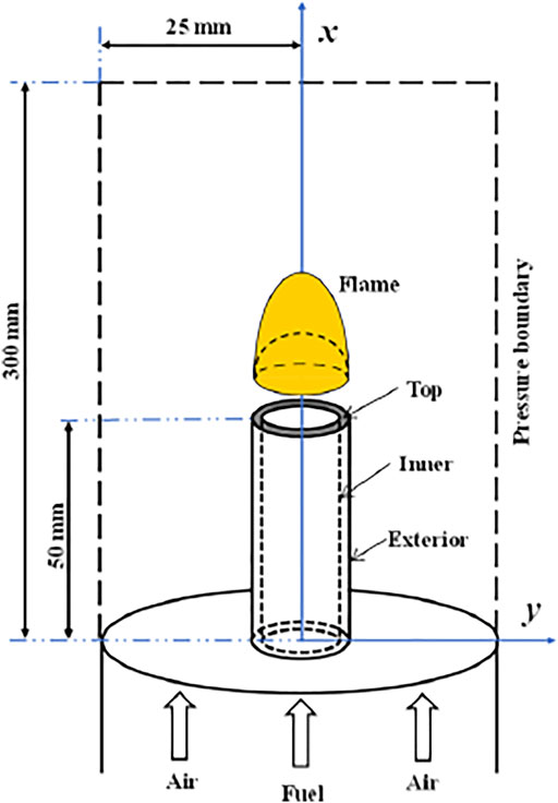
FIGURE 1. Physical model.
The continuum hypothesis and the Navier–Stokes equations are still suited to the present case for the Knudsen number, which is much smaller than the critical value of 10−3 (Beskok and Kamiadakis, 1999). The governing equations for the gaseous mixture includes mass, momentum, energy, and species conservation equations:
and the state equation:
where u is the velocity vector; the subscript i represents the different direction components in the space; ρ, µ, p, g, T, λ, Cp, and R0 are the density, viscosity, pressure, gravitational acceleration, temperature, thermal conductivity, heat capacity, and universal gas constant, respectively; and Dn, ωn, Yn, hn, and Mn are the mass diffusion coefficient, species production rate, mass fraction, enthalpy, and molecular weight, respectively. The subscript n represents a certain species.
The governing equations mentioned above were discretized by using the finite volume method and solved by using the open-source framework OpenFOAM (OpenFOAM, 2016). The SIMPLE algorithm was selected to deal with the pressure and velocity coupling in the equations. The laminar finite-rate reaction model was selected, since the experimental results showed that hydrogen micro-jet flame burn as laminar flame (Zhang et al., 2016). The C1 chemical mechanism (Bilger et al., 1999), which includes 17 species and 58 reactions, was employed in the study. Ever since, it was shown that the hydrogen micro-jet flames computed by using the C1 and GRI 3.0 (Smith et al., 1999) mechanisms are the same (Li et al., 2018). Thermodynamic and transport properties of the gaseous species were obtained from the database of CHEMKIN-PRO (CHEMKIN, 2013). The specific heat and density of mixture gas were calculated by mixing law and incompressible ideal gas law, respectively.
The velocity inlet boundaries were used for the fuel and air inlets, and the pressure boundary condition (1.0 atm) was specified at the outlet. The fuel stream was injected into the coflow air at a flow velocity of 5 cm/s. A uniform velocity profile of air coflow was achieved at the inlet by using a ceramic honeycomb. The initial temperatures of fuel and air were 300 K. The thermal conductivity of the stainless steel solid tube is set as 16.27 W/(m • K). The overall calculation domain is 300 mm × 25 mm, which is sufficiently larger than the jet flame. It was confirmed that a further increase in the computation domain has negligible effect on the computation results.
The quadrangular grids were adopted, and refined grids were utilized near the tube wall for high resolution in the numerical computation. The grid size is 17 μm at the tube exit and gradually stretched toward the far boundaries. The independence of the grid was confirmed under different flow conditions, and a set of grids with 169,000 cells was employed. The simulation convergence was confirmed when the residuals of all governing equations approached steady states. A steady state was declared until the fluctuation of the maximum flame temperature was less than 1 K. Convergence of the result was achieved based on the residuals to be less than 10−6.
Results and discussion
Validation of the computational method
The experimental study of hydrogen micro-jet flames has been conducted in our previous work (Zhang et al., 2016). The present computation method was validated by comparison with the experimental results at different tube diameter and wall thickness conditions. The hydrogen micro-jet flames achieved by micro-tubes with inner diameters (4) of 0.28 and 0.71 mm and wall thickness (δ) of 0.1 and 0.17 mm were measured by using planar laser-induced fluorescence technique for OH radical (OH-PLIF). The OH-PLIF system, based on a LaVision LIF system, was employed. The OH fluorescence was captured by an ICCD camera, which was perpendicular to the laser sheet. The detailed OH-PLIF measurement method was given in the literature (Zhang et al., 2016; Li et al., 2017). To obtain the whole OH chemiluminescent image of the flame, the laser sheet covered the fuel tube tip. The missing OH fluorescence could be found on the bottom right corner of the flame due to the block of the opaque solid tube on the opposite side of the laser beam; therefore, the OH contours obtained from experiment are asymmetric. It was further demonstrated that the fuel tube tip is circled by the OH zone, and the flames attached to the exterior surface of the solid tube.
The measured and computed OH distributions are shown in Figure 2. The variations in measured and computed height to width aspect ratios of flames (defined by OH distributions of the micro-flames) at different fuel flow Reynolds numbers (Re) are plotted in Figure 3. The height-to-width ratio, which reflects the flame deformation rate, increases with Re, and the measurements agree well with the computed results with differences less than 4%. It can be found that the flame shapes obtained from both experiment and computation are in good agreement. Consequently, it is reasonable to believe that the characteristics of hydrogen micro-jet diffusion flame with different wall thicknesses can be captured by the present numerical method.
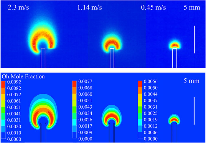
FIGURE 2. Measured (above) and computed (below) OH contours of hydrogen micro-jet flames at different fuel flow velocities (d = 0.71 mm, δ = 0.17 mm).
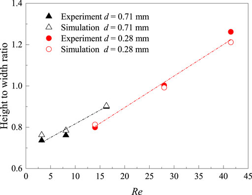
FIGURE 3. Comparison of the measured and computed height-to-width ratios of the flame achieved by micro-tubes with different inner diameters and wall thicknesses (case 1: d = 0.71 mm, δ = 0.17 mm; case 2: d 0.28 mm, δ = 0.1 mm).
Temperature distributions and fuel conversion ratio
The hydrogen micro-jet flames with tube (d = 0.42 mm) wall thickness of 0.14, 0.36, and 0.84 mm at different fuel jet velocities were computed. Figure 4 shows that the maximum flame temperature decreases smoothly with decreasing fuel flow velocity in the velocity range of 1–5 m/s. However, a rapid decrease can be seen in the velocity range of 0.4–1 m/s. It can be found that the maximum flame temperature decreases with the increasing wall thickness at the same fuel velocity. The temperature difference between the flames is significant in the high flow-velocity range, while the difference is modest in the low-velocity region.
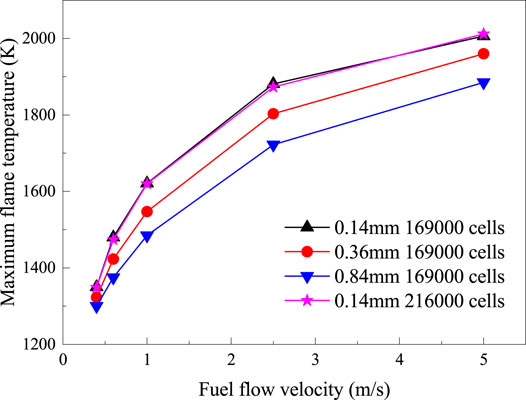
FIGURE 4. The variation of computed maximum flame temperature versus fuel flow velocity with different wall thicknesses and mesh densities (δ = 0.14, 0.36, and 0.84 mm).
Figure 5 shows the temperature contours of the nonpremixed hydrogen micro-jet flames with three different tube wall thicknesses. It can be seen that variations in temperature distributions versus fuel flow velocities are similar for the flames with thin- and thick-walled tubes. The high-temperature region shrinks gradually with the decreasing fuel velocity. The temperature distribution is influenced by the wall thickness. At high fuel velocity of 2.5 m/s, the top surface of the thick-walled tube is partly in the high-temperature region, while a greater area of the thin-walled tube is immersed in the region. Compared with the thin-walled tube case, the high-temperature region is smaller at a fuel velocity of 1 m/s for the thick-walled tube. Moreover, the high-temperature region moves to the tube exit at a low fuel velocity, 0.4 m/s, and the gaseous temperature around the exit of the thin-walled tube is significantly higher than that of the thick-walled tube.
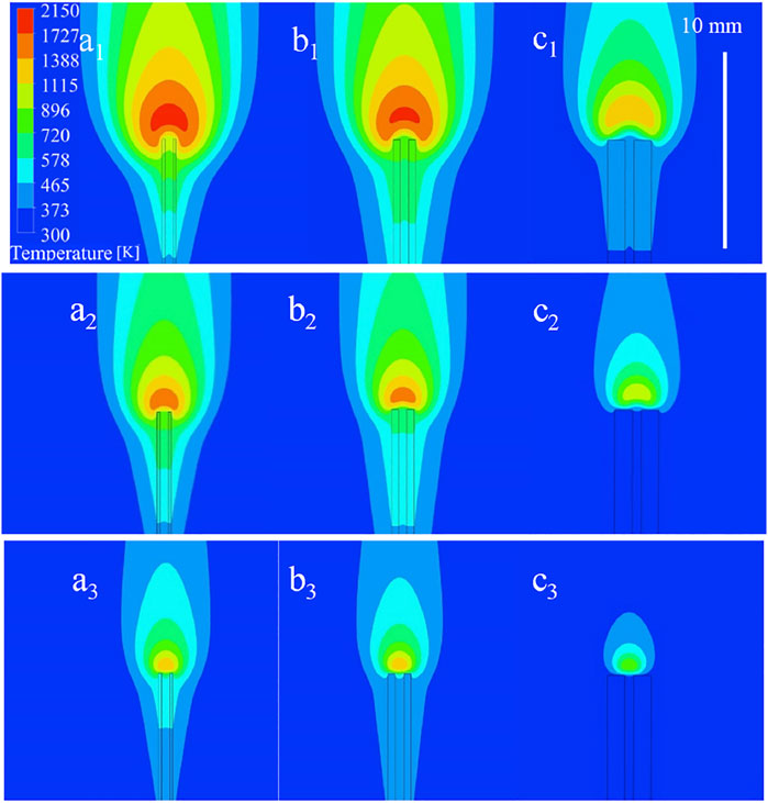
FIGURE 5. Temperature distributions of flames at different flow conditions (a1) δ = 0.14 mm, 2.5 m/s; (b1) δ = 0.36 mm, 2.5 m/s; (c1) δ = 0.84 mm, 2.5 m/s; (a2) δ = 0.14 mm, 1 m/s; (b2) δ = 0.36 mm, 1 m/s; (c2) δ = 0.84 mm, 1 m/s; (a3) δ = 0.14 mm, 0.4 m/s; (b3) δ = 0.36 mm, 0.4 m/s; (c3) δ = 0.84 mm, 0.4 m/s.
The computational temperature distributions in the solid tubes can also be seen in Figure 5. It can be seen that the solid micro-tube was heated by the micro-flame. The variation in the high-temperature region of flame affects the temperature of the solid micro-tube. The temperature profiles on the centerline of the solid tube wall (x direction) with different thicknesses were analyzed since it was reported that the preheating effect plays a key role in the temperature distributions and the flow fields around the tube exit (Fujiwara and Nakamura, 2013).
The temperature profiles on the centerline of the solid tube at different conditions are drawn in Figure 6 (the tube exit is at x = 50 mm). The temperature in the solid tube increases along the distance from inlet to exit in all cases, and the peak temperature position is on the top surface of the tube exit. The maximum temperature (967 K) at δ = 0.14 mm, 2.5 m/s is higher than that of the other cases, and the maximum temperature (387 K) at δ = 0.84 mm, 0.4 m/s is the lowest. The comparison shows that the maximum temperature of the solid tube decreases with decreasing fuel jet velocity. Although the solid temperature of the tube with a thick wall is relatively uniform, the maximum solid temperature of the thin-walled tube is much higher than the thick-walled tube at the same fuel flow velocity. It can be concluded that reduced wall thickness can increase the centerline temperature of the tube wall near the tube exit.
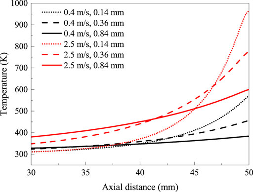
FIGURE 6. Temperature profiles on the centerline of the tube walls for different wall thicknesses.
The fuel conversion ratios of flame with different wall thicknesses at the fuel jet velocity of 0.4–5 m/s were also compared. The hydrogen conversion ratio α is computed as follows:
where
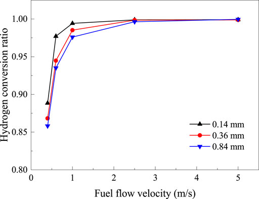
FIGURE 7. The variation of hydrogen conversion ratio versus fuel flow velocity with different wall thicknesses (δ = 0.14, 0.36, and 0.84 mm).
The maximum conversion ratio (approaching 100%) can be achieved at high fuel flow velocity (≥2.5 m/s) for the tubes with different wall thicknesses, and there exists a strong preheating effect. It is observed that the maximum conversion ratio values for these cases have little distinctions. However, the flame issued from the thin-walled tube (δ = 0.14 mm) reaches the peak value at a smaller fuel velocity. The results reveals that the thin-walled tube is more appropriate in achieving a relatively complete combustion.
Flame structures
In order to further clarify the effects of wall thickness on the flame structures and thermal interactions, the computational OH distributions of the micro diffusion flames were analyzed, as shown in Figure 8. It can be seen that the OH distributions are affected by the wall thickness.
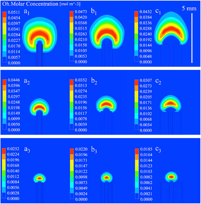
FIGURE 8. Computed OH mole concentrations of flames at different flow conditions (a1) δ = 0.14 mm, 2.5 m/s; (b1) δ = 0.36 mm, 2.5 m/s; (c1) δ = 0.84 mm, 2.5 m/s; (a2) δ = 0.14 mm, 1 m/s; (b2) δ = 0.36 mm, 1 m/s; (c2) δ = 0.84 mm, 1 m/s; (a3) δ = 0.14 mm, 0.4 m/s; (b3) δ = 0.36 mm, 0.4 m/s; (c3) δ = 0.84 mm, 0.4 m/s.
The top section of the solid tube is tightly circled by the OH zone for the thin-walled tube at a fuel flow velocity of 2.5 m/s (Figure 8a1), and a spherical flame attaches the lip of the tube, whereas the contact area between the flame and the thick-walled tube is significantly smaller for the thick tube (Figure 8c1). The attachment region is transferred from the exterior surface to the top surface, and the shape of the flames changed from sphere to hemisphere. When the fuel velocity decreases to 1 m/s, the OH zone shifts to the exit of the tube, the OH zone locates on the top surface of the thick wall in Figures 8b2, c2, and the flames turn from hemisphere shape to umbrella shape. However, the flame achieved by the thin-walled tube still adheres to the exterior surface (Figure 8a2). At the near-extinction limit, where the fuel velocity is 0.4 m/s, the umbrella-shaped OH regions are floated on the tube exit, the bottom of the small OH zones are flat, and it can be seen that the effect of wall thickness on the OH distribution is not significant.
The maximum OH mole concentrations of flames achieved by the different tube wall thicknesses also show distinction, except the main difference in flame shape and attachment behavior. It can be found that the maximum OH mole concentration decreases with increase in the wall thickness.
Effect of wall thickness on heat recirculation
To further compare the heat recirculation through the tube walls to the fuel, which can enhance the combustion, the thermal interactions at three different wall thicknesses (δ = 0.14, 0.36, and 0.84 mm) were also analyzed. The heat transfers through the wall surfaces at different fuel flow velocities were analyzed, and the case at a fuel flow velocity of 2.5 m/s are shown in Figure 9 for a demonstration. The heats absorbed from the flame through the top and exterior surfaces are finally transferred to the fuel steam via the inner surface for the thin-walled case (δ = 0.14 mm). However, the absorbed heats from the top surfaces are dissipated to the fuel and air streams through the inner and exterior surfaces for the thick-walled tube cases. The heat dissipated to coflow ambient through the exterior surfaces is increased with increasing wall thickness, and the corresponding maximum temperature of the solid tube is decreased. The results also show that the heat transfers through the inner surface deceases with increasing thickness.
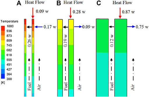
FIGURE 9. Schematic of heat exchanges through surfaces at fuel flow velocity of 2.5 m/s: (A) δ = 0.14 mm; (B) δ = 0.36 mm; (C) δ = 0.84 mm.
The net heat transfer to the fuel steam, which can benefit the flame, was calculated and normalized by the total heat absorbed by the wall surfaces. The normalized heat exchanges for preheating fuel QN was defined as follows:
where q, A are the local heat flux density and the corresponding surface (inner surface) area, respectively. Qt is the total heat absorption through other wall surfaces. The results at different fuel flow velocities are plotted in Figure 10, and the positive and negative values on the vertical axis mean heat absorption and heat dissipation, respectively. The results reveal that reducing the thermal conductive wall thickness can improve the heat recirculation at fuel velocities of 1 and 2.5 m/s, while all the micro-tubes play a negative role on the hydrogen flame at the fuel velocity of 0.4 m/s because the heat is transferred from the gas to the inner surfaces. It can be seen that the heat loss through the inner surface of thin-walled cases is lower than those of thick-walled cases, due to the difference in flame structure and temperature distribution (Figures 5 and 8). However, the heat exchanges through inner surfaces only account for a small percentage of the total heat absorption at low fuel velocity. The heat loss through the exterior surfaces is mainly from the absorbed heat from the top surface of the solid tube.
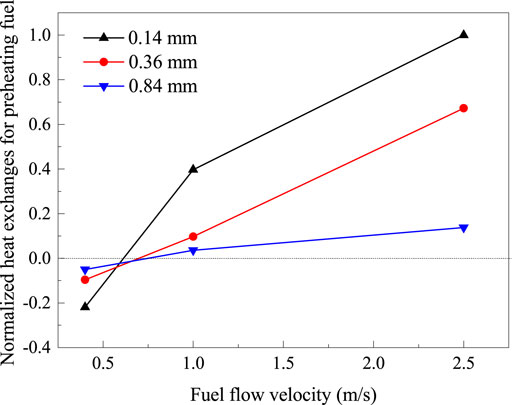
FIGURE 10. Normalized heat exchanges responsible for preheating fuel at different fuel flow velocities (δ = 0.14, 0.36, and 0.84 mm).
Numerical experiment
As known, a properly maintained high wall temperature and utilized heat recirculation can facilitate the gas reaction and enhance the flame. To provide guidance for the thermal management of the jet flame burner, especially for the thick-walled tube, an innovative numerical experiment was conducted to compensate for the negative effect of heat loss. An artificial wall boundary condition was used, where the exterior surface of the tube wall was treated as an adiabatic wall boundary, while the top and inner surfaces were thermal coupling boundaries.
The computational flame temperature with real and artificial wall conditions at the fuel velocities of 0.4 and 2.5 m/s were compared, and the wall thickness was fixed at δ = 0.36 mm. The gas temperature profiles along the centerline (x direction, y = 0) with both the conjugate wall and adiabatic wall boundary conditions are shown in Figure 11 (the tube exit is at the position x = 50 mm). At the fuel velocity of 0.4 m/s, the maximum temperature of the flame and the fuel temperature in the tube with the adiabatic exterior surface are significantly higher than those of the real wall tubes. A similar behavior can be found in the case of the high fuel velocity (2.5 m/s), although the temperature difference is reduced. The numerical results indicate that the preheating effect on the fuel is enhanced, and the maximum flame temperature on the centerline is increased when the heat loss through the exterior surface of the relatively thick wall tube is suppressed.
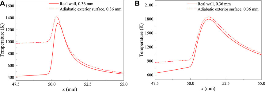
FIGURE 11. Temperature profiles along the centerline under real and artificial wall boundary conditions: (A) 0.4 m/s, δ = 0.36 mm; (B) 2.5 m/s, δ = 0.36 mm.
The results of combustion efficiency (η) with different wall boundaries are calculated and shown in Figure 12, and the combustion efficiency is defined as follows:
where Q, H, and
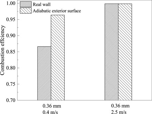
FIGURE 12. The variation in combustion efficiency under real and artificial wall boundary conditions (0.4 and 2.5 m/s, δ = 0.36 mm).
Conclusion
The combustion characteristics of hydrogen diffusion flames achieved by micro-tubes with different wall thicknesses and the same inner diameter were investigated numerically to clarify the effect of wall thickness on the flame behaviors and combustion efficiency.
The computed temperature and OH distributions show a remarkable difference when wall thickness is changed. The hydrogen conversion ratios, which reflect the combustion efficiency for tubes with different all thicknesses are almost the same at high fuel jet velocity. However, the hydrogen conversion ratio is decreased with the increase in wall thickness at low fuel flow velocity. The thin-walled tube is more appropriate in maintaining a high fuel conversion ratio.
The computational maximum flame, solid temperatures, and maximum OH mole concentration decrease with increasing wall thickness at a fixed fuel flow velocity. The heat exchange between the flame and solid tube through the top surface is increased with the wall thickness. However, the heat recirculation to the fuel stream is decreased, since the heat loss from the exterior surface is increased. The effect of wall thickness on the micro-jet flame is mainly through its influence on the flame shapes and heat exchange areas of the exterior and top surfaces.
A numerical experiment on the heat conduction characteristics of the exterior surface has been conducted. The results show that the hydrogen micro-jet flame achieved by a tube with a thick wall can be prompted by restraining the heat loss from the exterior surface.
Data Availability Statement
The original contributions presented in the study are included in the article/Supplementary Material, further inquiries can be directed to the corresponding authors.
Author Contributions
XL: conceptualization, supervision, methodology, investigation, reviewing and editing, and funding acquisition. SX: data curation, reviewing, and editing. JZ: methodology and investigation. DZ: supervision, reviewing, and editing. XW: reviewing and editing.
Funding
This work was supported by the DNL Cooperation Fund, CAS (DNL202006), and National Natural Science Foundation of China (No. 52176139).
Conflict of Interest
The authors declare that the research was conducted in the absence of any commercial or financial relationships that could be construed as a potential conflict of interest.
Publisher’s Note
All claims expressed in this article are solely those of the authors and do not necessarily represent those of their affiliated organizations, or those of the publisher, the editors, and the reviewers. Any product that may be evaluated in this article, or claim that may be made by its manufacturer, is not guaranteed or endorsed by the publisher.
References
Alazemi, J., and Andrews, J. (2015). Automotive Hydrogen Fuelling Stations: An International Review. Renew. Sust. Energ. Rev. 48, 483–499. doi:10.1016/j.rser.2015.03.085
Beskok, A., and Kamiadakis, G. E. (1999). A Model for Flows in Channels Pipes, and Ducts at Micro and Nano Scales. Microscale Therm. Eng. 3, 43–77. doi:10.1080/108939599199864
Bilger, R. W., Starner, S. H., and Kee, R. J. (1999). On Reduced Mechanisms for Methane-Air Combustion in Nonpremixed Flames. Combust. Flame 80, 135–149. doi:10.1016/0010-2180(90)90122-8
Cappelletti, A., and Martelli, F. (2017). Investigation of a Pure Hydrogen Fueled Gas Turbine Burner. Int. J. Hydrogen Energ. 42, 10513–10523. doi:10.1016/j.ijhydene.2017.02.104
Cheng, T. S., Chao, Y. C., Chen, C. P., and Wu, C. Y. (2008). Further Analysis of Chemical Kinetic Structure of a Standoff Microjet Methane Diffusion Flame Near Extinction. Combust. Flame 152, 461–467. doi:10.1016/j.combustflame.2007.10.007
Cheng, T. S., Chao, Y. C., Wu, C. Y., Li, Y. H., Nakamura, Y., Lee, K. Y., et al. (2005). Experimental and Numerical Investigation of Microscale Hydrogen Diffusion Flames. Proc. Combust. Inst. 30, 2489–2497. doi:10.1016/j.proci.2004.07.025
Choi, J., Lee, W., Rajasegar, R., Lee, T., and Yoo, J. (2021). Effects of Hydrogen Enhancement on Mesoscale Burner Array Flame Stability under Acoustic Perturbations. Int. J. Hydrogen Energ. 46, 37098–37107. doi:10.1016/j.ijhydene.2021.08.192
Dimitriou, P., and Tsujimura, T. (2017). A Review of Hydrogen as a Compression Ignition Engine Fuel. Int. J. Hydrogen Energ. 42, 24470–24486. doi:10.1016/j.ijhydene.2017.07.232
Fujiwara, K., and Nakamura, Y. (2013). Experimental Study on the Unique Stability Mechanism via Miniaturization of Jet Diffusion Flames (Micro-flame) by Utilizing Preheated Air System. Combust. Flame 160, 1373–1380. doi:10.1016/j.combustflame.2013.03.002
Gao, J., Hossain, A., Matsuoka, T., and Nakamura, Y. (2017). A Numerical Study on Heat-Recirculation Assisted Combustion for Small Scale Jet Diffusion Flames at Near-Extinction Condition. Combust. Flame 178, 182–194. doi:10.1016/j.combustflame.2016.12.028
Gao, J., Hossain, A., and Nakamura, Y. (2016). Flame Base Structures of Micro-jet Hydrogen/methane Diffusion Flames. Proc. Combust. Inst. 36, 4209–4216. doi:10.1016/j.proci.2016.08.034
Hossain, A., and Nakamura, Y. (2015). Thermal and Chemical Structures Formed in the Micro Burner of Miniaturized Hydrogen-Air Jet Flames. Proc. Combust. Inst. 35, 3413–3420. doi:10.1016/j.proci.2014.08.008
Jia, Z., Ye, Q., Wang, H., Li, H., and Shi, S. (2018). Numerical Simulation of a New Porous Medium Burner with Two Sections and Double Decks. Processes 6, 1–18. doi:10.3390/pr6100185
Kahraman, N., Tangöz, S., and Akansu, S. O. (2018). Numerical Analysis of a Gas Turbine Combustor Fueled by Hydrogen in Comparison with Jet-A Fuel. Fuel 217, 66–77. doi:10.1016/j.fuel.2017.12.071
Kuwana, K., Kato, S., Kosugi, A., Hirasawa, T., and Nakamura, Y. (2016). Experimental and Theoretical Study on the Interaction between Two Identical Micro-slot Diffusion Flames: Burner Pitch Effects. Combustion and Flame 165, 346–353. doi:10.1016/j.combustflame.2015.12.017
Li, J., Huang, H., Bai, Y., Li, S., and Kobayashi, N. (2018). Combustion and Heat Release Characteristics of Hydrogen/air Diffusion Flame on a Micro-jet Array Burner. Int. J. Hydrogen Energ. 43, 13563–13574. doi:10.1016/j.ijhydene.2018.04.195
Li, X., Zhang, J., Yang, H., Jiang, L., Wang, X., and Zhao, D. (2017). Combustion Characteristics of Non-premixed Methane Micro-jet Flame in Coflow Air and thermal Interaction between Flame and Micro Tube. Appl. Therm. Eng. 112, 296–303. doi:10.1016/j.applthermaleng.2016.10.082
Nozari, H., Karaca, G., Tuncer, O., and Karabeyoglu, A. (2017). Porous Medium Based Burner for Efficient and Clean Combustion of Ammonia-Hydrogen-Air Systems. Int. J. Hydrogen Energ. 42, 14775–14785. doi:10.1016/j.ijhydene.2017.03.234
OpenFOAM (2016). The Open Source CFD Toolbox. Available at: http://www.openfoam.org.
Rajasegar, R., Choi, J., McGann, B., Oldani, A., Lee, T., Hammack, S. D., et al. (2019). Mesoscale Burner Array Performance Analysis. Combust. Flame 199, 324–337. doi:10.1016/j.combustflame.2018.10.020
Sharma, S., and Ghoshal, S. K. (2015). Hydrogen the Future Transportation Fuel: From Production to Applications. Renew. Sust. Energ. Rev. 43, 1151–1158. doi:10.1016/j.rser.2014.11.093
Smith, G. P., Golden, D. M., Frenklach, M., Moriarty, N. W., Eiteneer, B., Goldenberg, M., et al. (1999). gri_mech. Available at: http://www.me.berkeley.edu/gri_mech/.
Yu, X., Du, Y., Sun, P., Liu, L., Wu, H., and Zuo, X. (2017). Effects of Hydrogen Direct Injection Strategy on Characteristics of Lean-Burn Hydrogen-Gasoline Engines. Fuel 208, 602–611. doi:10.1016/j.fuel.2017.07.059
Zareei, J., Rohani, A., and Wan Mahmood, W. M. F. (2018). Simulation of a Hydrogen/natural Gas Engine and Modelling of Engine Operating Parameters. Int. J. Hydrogen Energ. 43, 11639–11651. doi:10.1016/j.ijhydene.2018.02.047
Keywords: hydrogen, micro-jet flame, wall thickness, heat recirculation, combustion characteristics
Citation: Li X, Xie S, Zhang J, Zhao D and Wang X (2022) Numerical Study on the Effect of Wall Thickness on the Combustion Characteristics of Non-premixed Hydrogen Micro-jet Flame. Front. Energy Res. 10:847651. doi: 10.3389/fenrg.2022.847651
Received: 03 January 2022; Accepted: 20 January 2022;
Published: 04 March 2022.
Edited by:
Zhihua Wang, Zhejiang University, ChinaReviewed by:
Weijuan Yang, Zhejiang University, ChinaJianlong Wan, Huazhong University of Science and Technology, China
Huahua Xiao, University of Science and Technology of China, China
Copyright © 2022 Li, Xie, Zhang, Zhao and Wang. This is an open-access article distributed under the terms of the Creative Commons Attribution License (CC BY). The use, distribution or reproduction in other forums is permitted, provided the original author(s) and the copyright owner(s) are credited and that the original publication in this journal is cited, in accordance with accepted academic practice. No use, distribution or reproduction is permitted which does not comply with these terms.
*Correspondence: Xing Li, bGl4aW5nQG1zLmdpZWMuYWMuY24=; Jing Zhang, emhhbmdqaW5nQG1zLmdpZWMuYWMuY24=