 Ali Bughneda1
 Mohamed Salem
 Mohammad Alhuyi Nazari
 Salah Alatai
- 1School of Electrical and Electronic Engineering, Universiti Sains Malaysia (USM), Nibong Tebal, Malaysia
- 2Faculty of New Sciences and Technologies, University of Tehran, Tehran, Iran
Studies on resonant power converters (RPCs) have received much attention due to the rapid growth of their potential in modern power and renewable energy applications such as photovoltaic, electric vehicles, wind, and fuel cells. Consequently, a significant number of studies focusing on RPC topologies for renewable energy applications is available. Generally, these studies have addressed several aspects, such as the development of their soft switching feature, smooth waveforms, high power density, and high efficiency. With this in mind, the present paper aims to review the development of the RPCs, challenges in their development, and comparison between common topologies as highlighted in literature. In addition, the use of RPCs in various applications of renewable energy is highlighted, focusing on some of the recently utilized topologies based on their constructions and achievements. There are still several issues and challenges in research that need to be considered for future improvement of the RPC performance in renewable energy applications. The improvement may require modifications on the circuit design or control strategies.
1 Introduction
Electric vehicles (EVs), renewable energy systems (RES), smart grids, and solid-state transformers are some of the instances of modern industrial applications of clean energy in power electronics that have advanced rapidly over time. With this, much attention has been given to resonant DC–DC converters due to their characteristics and proven efficiency compared to normal converters. These resonant DC–DC converters, in particular, offer a better conversion rate, and can work at high switching frequencies and achieve soft switching (SS); they also result in a considerable size reduction in terms of the magnetic components of the system, such as the passive filters and transformers (Outeiro et al., 2016a). All these are necessary to meet the demands of industrial applications of power electronics applications. RPCs (resonant power converters) are also used. Furthermore, rather than incorporating extra equipment for each switch, RPCs use another way to accomplish the SS requirements. RPCs specifically structure them as a Resonant Tank Network (RTN) that consists of two, three, or more reactive elements that are connected with a converter in a cascade manner.
RTN might be classified according to their connection mechanisms and the number of employed tank elements (Outeiro et al., 2016a); however, the most prevalent 2-element type of RTN is the series resonant converter (SRC) and parallel resonant converter (PRC). An example of 3-element RTNs is the series-parallel RCs like LCC and LLC, whereas LCLC is an example of a multi-element RTN.
Furthermore, RPCs utilize other techniques to achieve the SS requirements rather than to embrace the additional equipment for each switch. Specifically, RPCs structure them as RTN using two, three, or multi-reactive components that are interconnected with the converter in cascade (Outeiro and Buja, 2015). Even though single-stage RCs are well-known and advanced in numerous applications, they still seem inappropriate for high input voltage applications. The current load on switching devices, in particular, has the potential to compromise and degrade both reliability and efficiency (Lee and Moon, 2011); hence, multilayer converters were developed, allowing the use of low-voltage switching devices in high-voltage applications (Liu et al., 2017; Salem et al., 2019).
Given the high interest on RPCs nowadays, the present paper aims to review the construction, classification, and development of RPCs and their applications. The paper also wishes to introduce the latest RPC technologies as reported in existing literature. The paper is organized in the following structure: Section 2 highlights the structure and classification of RPCs. Section 3 reviews the use of RPC in renewable energy applications while Section 4 provides some recommendation for future work on RPCs in renewable energy application. Finally, Section 5 concludes the paper.
2 Resonant Power Converters
There are many soft-switching converters (SSCs) that have been developed successfully in the last few decades. These converters have enabled power semiconductor devices in switch-mode power supplies (SMPS) to operate at preferred conditions, consequently resulting in better performance, high power density, and efficiency (Moradisizkoohi and Mohammed, 2017; Geetha et al., 2018). In general, the SSCs can be grouped into three different families according to their operating principles (Outeiro and Buja, 2015): (1) quasi RCs (QRCs) and multi RCs (MRCs) (Liu et al., 1987; Moradisizkoohi and Mohammed, 2017; Geetha et al., 2018), (2) resonant-transition converters (RTCs) (Tuomainen and Kyyra, 2005; Martins et al., 2006), and (3) RPCs. Figure 1 shows the SSC family.
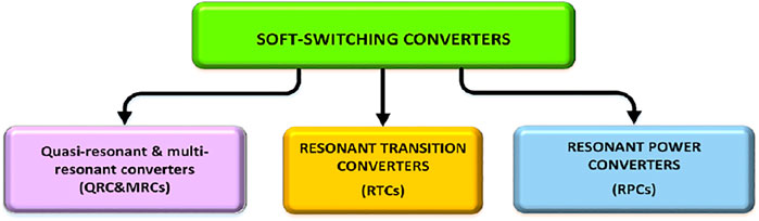
FIGURE 1. Soft-switching converter family (Salem et al., 2018).
Of the three types, RPCs have received greater attention due to the developments in their usage and the industrial application. Efforts have been placed to further enhance the soft-switching, smooth waveforms, and high efficiency of RPCs. RPCs are found to be ideal for use in high-voltage applications. This is due to their capacity to minimize switching losses and have low switching stresses, low EMI, and high power density (Outeiro et al., 2014). As a result, RPCs are the most preferred converters in industrial high-power systems compared to the traditional converters due to their features of working at high frequencies and achieving SS. Meanwhile, studies have suggested that certain aspects of RPCs need improvement, such as the wide load fluctuations, dependability, high power density, fewer number of components, high efficiency, tiny size, low cost, and light weight (Batarseh, 1994; Chien et al., 2013). This particular section focuses on RPCs in terms of their structure and number of reactive components.
2.1 Structure of Resonant Power Converters
The structure of RPC is produced by cascading different stages as depicted in Figure 2 (Outeiro and Buja, 2015).
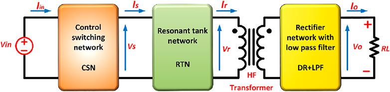
FIGURE 2. Structure of a resonant power converter (PRC) (Outeiro et al., 2016a).
2.1.1 Control Switching Network
The CSN is the layer for the conversion of the supplied DC power into AC power. The CSN switches are programmed to quickly switch ON/OFF based on the working frequency for the generation of the output voltage or current that feeds the next step (Salem et al., 2018). The CSN (Figure 3) is controlled to produce a square voltage VS(t) where its frequency (fs) is equal/close to the resonant frequency (fr). This can be expressed by the Fourier series in Eq. 1. CSN is commonly used with either a half- or full-bridge configuration, but the employed configuration is determined by the required power. High-power applications are mostly operated with the full-bridge inverter while half-bridge configuration (with low voltage switch rates) is more ideal for high input voltage systems (Outeiro et al., 2014).
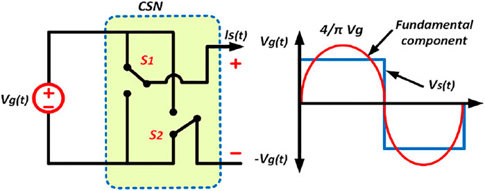
FIGURE 3. Equivalent circuit of CSN (Alatai et al., 2021).
Wide-band gap devices are used in resonant converters to improve power density and efficiency. These devices have a substantially higher figure of merit, allowing them to significantly boost power density and efficiency. Silicon carbide (SiC) devices can run at hundreds of thousands of frequencies to achieve higher power densities. The size of the passive components is reduced while operating at a higher switching frequency. The ON state resistance of the SiC-based MOSFETs is significantly lower than that of Si-based MOSFETs for the same conduction current rating. As a result, the conduction losses of the SiC-based MOSFETs are lower, making them more efficient. Hence, these devices are thought to be a good choice for on-board chargers (OBCs). Despite the benefits of SiC and GaN devices, there are a few drawbacks, such as their high cost, difficult gate driver design, and complex EMI protection design. Furthermore, increasing the working temperature from 50 to 150° reduces the efficiency of GaN and SiC by 4% (Deshmukh et al., 2022).
2.1.2 Resonant Tank Network
The RTN, also called a tuned circuit, resonant circuit, LC circuit, or tank circuit, is the next level. It is made up of reactive elements for the storage of vacillating energy at the circuit’s resonant frequency. The RTN stage of RPCs is the most significant. In the high-frequency RTN, a stage is made up of 2, 3, or more elements. Capacitors (C) and inductors (L) are the devices for passive energy storage and can be coupled in a variety of ways. Electromagnetic interference (EMI) and harmonic distortion (HD) are prevented by using these reactive components to generate current signals and sinusoidal voltage (Salem et al., 2018). This period can be selected by the frequency selective network because it serves as an energy buffer between the load and the CSN as seen in Figure 2. In resonance condition, the capacitance and inductance have equal impedances, paving the way for the generation of the resonant frequency (Salem and Yahya, 2019). RTNs can be classified based on either the number of utilized reactive elements in the RTN or the manner of connection of the elements. The group that is based on the connection mechanisms has three common representative resonant circuits, which are SRC, PRC, and SPRC (Salem et al., 2018). The second group that depends on the number of the reactive elements is classified into two-element resonant tank (second-order), three-element resonant tank (third-order), and multi-element resonant tank (fourth-, fifth-order …). These types have many topologies; as a result, the more members in an RTN, the more topologies are possible. However, not all element combinations can result in a resonant condition (Batarseh, 1994). The appropriate design and selection of RTN elements, as well as the appropriate selection of the control mechanism may conserve SS over a large load range; it also ensures constant converter output voltage, and improve power conversion capabilities and efficiency (Outeiro et al., 2016a).
2.1.3 Diode Rectifier Network With Low Pass Filter
This is the final stage in the structure of the resonance power converter. The input is a sinusoidal voltage and current waveforms, produced at the resonant frequency in the previous stage; this input works as a pass filter that eliminates the voltage harmonics of the core component generated by the CSN at its output. Then, it feeds the conditioning circuitry (CC) stage at its input as a pulse waveform. The CC stage consists of a diode rectifier DR and a low-pass filter (capacitive and inductive) LPF (Figure 4). The main function of the DR-LPF stage is to filter and rectify the AC signal that comes from the resonance tank in order to get the DC output signal that is required to supply the load. A filter (capacitive and inductive) determines the sink nature of the current/voltage of the load. The DR with both types of filter (capacitive and inductive) has been highlighted in several works (Outeiro et al., 2014; Salem et al., 2018).
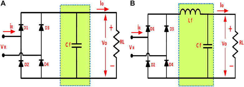
FIGURE 4. (A) DR with capacitive LPF, (B) DR with inductive LPF (Outeiro et al., 2016a).
2.2 Classification of Resonant Power Converters
RPCs can be categorized based on the number of employed reactive components in the RTN; the classes include 2 elements, 3 elements, and multi-elements (Figure 5).
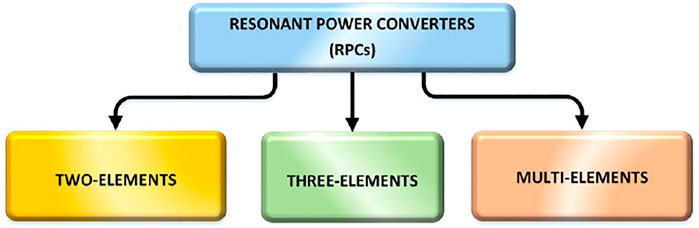
FIGURE 5. Clarification of resonant power converters (RPCs) (Alatai et al., 2021).
2.2.1 Two-Element Resonant Power Converters Topologies
The two-element RTN or the second-order RC is further categorized into SRC (Figure 6A) (Ibanez et al., 2015; Witulski et al., 1986; Salem et al., 2014) and PRC (Figure 6B), (Lin et al., 2013; Saha et al., 2018). As seen in Figure 7, 2-element RPCs are available in eight topologies that have simple circuit structure and minimal components; their storage tank is made up of just two elements for energy storage. As in Figure 7, the topologies at the top (a–d) are ideal for voltage source inputs, while the ones in the bottom (e–h) are ideal for current source converters (Outeiro et al., 2016a). In SRC, the LC elements are connected in series with the effective load resistance Re (Figure 6) (the topology b). Consequently, increases in Re decreases the current through the CSN and RTN switches, and vice versa. SRCs exhibit lower EMI than the hard switched converters, which significantly reduces the size and switching-related losses. Hence, they offer high power supplies and achieved better conversion efficiency (Abdul-Hakeem et al., 2018; Bhuvaneswari et al., 2018).
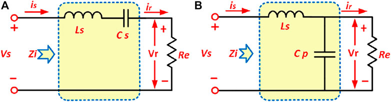
FIGURE 6. AC equivalent circuits of two-element RPC topologies (Outeiro et al., 2016a).
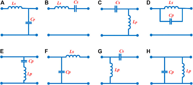
FIGURE 7. Two-element resonant tank network topologies (Salem et al., 2018).
As indicated in Figures 7A,D,H, PRCs have one or both LC elements parallelly connected with the effective load resistance, Re. These converters are capable of generating a constant regulated current that protects against short circuits. For a PRC, the output voltage can be increased and decreased. The output voltage of a PRC can be controlled from full load to no load by operating at a frequency above resonance. Furthermore, it is excellent for use in short circuits to the point that even when the load falls, the conduction losses remain constant in the semiconductor devices; the efficiency is also high for light loads (Bhuvaneswari and Babu, 2016). Because of the low switching losses of this converter, it is ideal for use in high-frequency, high-power systems. PRC functions as a constant source of current when the resonant and switching frequencies are equal. However, at lower switching frequencies compared to the PRC, it is more of a constant voltage source for the output voltage and has wide load fluctuation. It is the best choice for voltage regulators (Azura et al., 2014). At high input voltage, PRCs exhibit a high switch off current and high circulating energy, and those are the two major problems of PRCs (Huang, 2014). The disadvantage of SRC is the sharing of the input voltage between the load and the resonant impedance, which results in a DC gain of less than one. SRC is known to exhibit substantially higher nonlinear dynamics, which makes the control more difficult. On the other hand, the SRC output voltage cannot be adjusted when there is no load (Salem et al., 2017a). For the PRC, the voltage gain might be greater than one when compared to SRC. As a result, PRC has the ability to increase voltage. The operating area of PRCs, on the other hand, is substantially smaller. When the load is light, there is no need for much frequency fluctuation to control the output voltage (Huang, 2014). Also, based on Martinez et al. (2018), it was confirmed that parasitic resistances presented in the windings of the coupled inductors have a great impact on the voltage gain and the efficiency. In particular, it was observed that a converter with a large number of components increases the probability of parasitic resistance’s negative effect on voltage gain and efficiency. Also, by considering the analysis of power core loss of the resonant inductor Lr function, it was noticed that the volume, core cross-section area, number of turns, and the type of copper used in high-frequency inductors and transformers are the main impacts of copper losses. Thus, by using the proper copper material with low inductance value, and reducing the size of volume and cross-section area, the effect on efficiency and voltage gain will be significantly decreased (Salem et al., 2022).
2.2.2 Three-Element Resonant Power Converters Topologies
There are 36 topologies in the third-order resonant tanks (three-element RTN) or higher-order resonant tanks. The three-component RPC has one additional element than the two-element RPCs. Figure 8 illustrates some three-element RTN topologies (Severns, 1992), where resonant tanks A-1 to A-9 are composed of two inductors and one capacitor and RTNs B-1 to B-9 are composed of two capacitors and one inductor. These topologies with third-order resonant tanks (Huang et al., 2011; Tan and Ruan, 2016; Fei, 2018) have been suggested to eliminate the disadvantage of two-element topology as they are seen as a hybridization of the benefits of most 2-element RPCs (SRC and PRC) (Salem et al., 2020). These 3-element RPCs have features that make them suitable for both light and heavy load applications (Beiranvand et al., 2011). Furthermore, they are capable of efficiently transferring power from the source to the end-users.
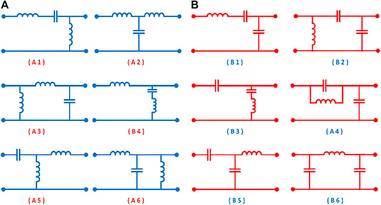
FIGURE 8. (A) Topologies with 2L and 1C. (B) Topologies with 2C and 1L (Salem et al., 2018).
Another benefit of 3-element RPCs is that the propagated waveform is frequently sinusoidal, which means that the THD of the output waveform is virtually zero. The EMI of a well-known procedure for mono-frequency waveform transfer is generally low (Luo and Ye, 2016). These topologies work with half-bridge or full-bridge inverters. Compared to the conventional second-order RPCs, the higher-order RPCs have more desirable properties. Furthermore, the variety of resonant topologies allows the designer to select the most suitable topology for their application. The stable analysis of these converters, however, becomes more complex because they are high-order nonlinear systems (Batarseh, 1994). Three-element RCs have been explored and tested in a variety of systems. Among them are the LLC RC and LCC RPC, which are the most common 3-element RTNs. Many other topologies have also been studied, such as the CLL-RPC and LCL-RPC. Some of these topologies will be thoroughly reviewed later.
2.2.3 Multi-Element Resonant Power Converters Topologies
These are RTNs with four or more LC components; they exist in about 98 different topologies, some of which are shown in Figure 9A. (Batarseh, 1994). Five-element topologies exist in hundreds of topologies as seen in Figure 9B. Compared to three-element RPCs, multi-element RPCs have more benefits as most of the benefits of the lower-order RPCs are also found in the multi-element RPCs (Outeiro et al., 2016a). The RPC performance of multi-element RPCs is relatively high; they also offer reduced circulating energy and intrinsic current protection. Furthermore, these converters can work with a short output circuit. Multi-element RPCs can achieve zero current switching (ZCS) on the primary side of the device and zero voltage switching (ZVS) on the secondary side. These multi-element RPCs have a high power density and are DC–DC converters with a high efficiency (Fu et al., 2008). They achieve very low switching losses due to soft-switching action. Furthermore, the injection of the third-order harmonic improves the power process of these converters compared to standard RCs. Hence, the RMS and peak currents of the RTN are lowered, and the current and conduction losses are reduced in the devices as well. Third-order harmonics are also injected into the output voltage in this topology to boost the RMS value (Fu et al., 2008).
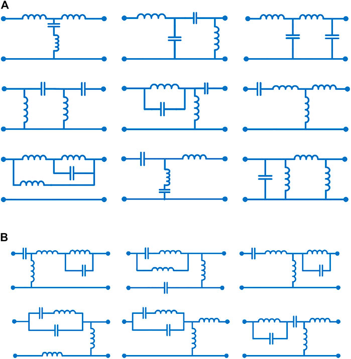
FIGURE 9. (A) Topologies of 4-element resonant tanks (Salem et al., 2018). (B) Topologies of 5-element resonant tanks (Outeiro et al., 2016a).
Multi-element topologies have been reviewed in a number of studies. The classification and a comparison of different topologies of multi-element RPCs are presented in Huang et al. (2011) and Outeiro and Buja (2015). The LCLC topology of fourth-order RTs is presented in Ang (2006) and Outeiro et al. (2016b). This topology combines the LLC and LCC properties. A common application area of the LCLC RCs is in PV systems where it is used in the maximum power point tracker (MPPT) (Conesa et al., 2009); it is also used in electric vehicle charging (Lu et al., 2015) and others. The LCLC RPC can also be used in high-voltage, high-efficiency applications (Zhao et al., 2017a). In Koscelnik et al. (2014), a review on multi-RPCs is presented and three topologies have been selected: LCTLC, LCLCL, and LCL2C2. However, the topology of LCL2C2 is still not extensively investigated. The connection allows for multifunctional outputs such as DC, AC with HF, or LF. The LCL2C2 topology is also short-circuit proof; hence, LCL2C2 can be connected without a transformer and still achieve a 97% conversion efficiency. The system can also achieve THD approximately 4.5% and up to 93 W/in3 power density (Dobrucky and Koscelnik, 2005). LCTLC topology can achieve up to 94% power density and THD of less than 5%; all these are in line with equipment requirements. At the point of equal switching frequency values, the voltage transfer function demonstrates that the resonant frequency gains equal one; however, the converter is unaffected by the load size in this situation. The same three topologies of multi-RPCs (LCTLC, LCLCL, and LCL2C2) are described and analyzed in Dobrucky and Koscelnik (2005). The multi-RPC is a viable alternative to the existing DC–DC converters.
2.3 LLC Resonant Converter
This is one of the most common 3-element RPCs; they contain three reactive elements, which are a series inductor, a parallel inductor, and a series capacitor. The two inductors (Ls and Lp) together with the capacitor (Cs) form a RTN. Figure 10A depicts a circuit of the LLC RPC; it is seen as a normal SRC with an additional inductor parallel Lp to the load (Yang et al., 2002; Salem et al., 2018).
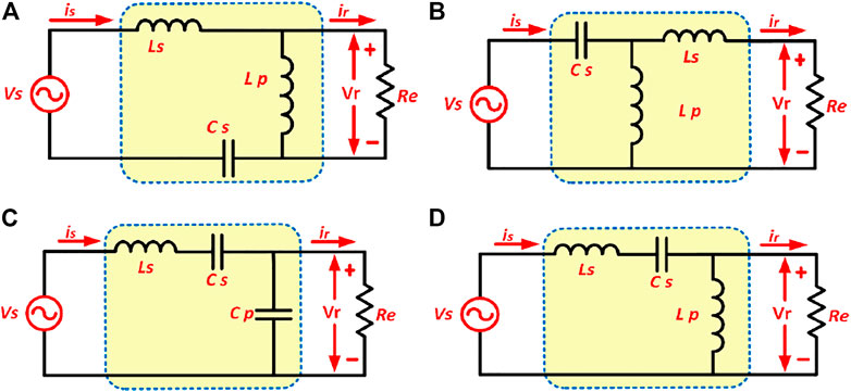
FIGURE 10. Equivalent circuits of (A) LLC resonant converter circuit (Alatai et al., 2020); (B) CLL resonant converter circuit (Salem and Yahya, 2019); (C) LCC resonant converter (Outeiro et al., 2016a); (D) LCL resonant converter (Alatai et al., 2021).
It is also worth highlighting that there is a topology similar to LLC in the number and type of reactive element, that is, CLL topology. Both topologies are found to have two inductors, and one capacitor (2L + Cs), with a different arrangement in the resonant tank. The series inductor in the CLL is connected to the RTN’s output, whereas the series inductor in the LLC is connected to the RTN’s input and is in series with the capacitor. The CLL equivalent circuit, as seen in Figure 10B, is made up of a capacitor Cs serially connected to the input (which serves as both a resonance aid and a direct current blocker), an inductor Ls serially connected to the load, and a second inductor Lp parallelly connected between the inductor Ls and the capacitor Cs. The CLL topology presents the same behavior and shortcomings as in LLC but is able to integrate the leakage inductance of the HF transformer in the RTN (Colak et al., 2015; Outeiro et al., 2016a).
The LLC topology generates two resonant frequencies across the whole operating scope, one of which depends on the series inductor Ls and capacitor Cs and is called series resonant frequency (frs), while the other is dependent on the three elements Ls, Cs, and Lp together, and it is called fundamental resonant frequency (frp) (Liu, 2017). frs and frp are shown in Eqs. 2, 3 (Salem et al., 2018).
The two resonant inductances AL are related as established in Eq. 4; this is the most important concept when constructing the LLC converter. The relationship between the input voltage and the output voltage is called the voltage-gain function, which provides the basis of the LLC RPC design; it is derived using Eq. 5. When it is operating at series resonant frequency, the LLC and SRC exhibit similar characteristics. Under light load situations, LLC functions more like PRC; however, it operates similarly to SRC under heavy loads. At the system resonant frequency, the peak gain occurs between the fundamental (frp) and series (frs) resonant frequencies (Liu, 2017; Salem et al., 2018).
The LLC RC has drawn much more attention because it gives many advantages over conventional RPCs with two elements (SRC and PRC). At the same time, it reduces their limitations. LLC topology by using an inductor parallel to the resonant capacitor can achieve no-load control, which is impossible to achieve in the SRC (Outeiro et al., 2016a). In this converter, however, excellent efficiency can be achieved when operating over a wide load range (no load to maximum load), a wide input voltage range, and a limited range of switching frequency, which makes wide output regulation range. The primary and secondary side rectifiers of an LLC can achieve ZVS and ZCS, respectively; they can also achieve minimal voltage stress on the secondary rectifier because this converter does not need to use secondary filter inductor voltage stress.Hence, there is a possibility of reducing the voltage stress on the diodes of the rectifier by twofold compared to the output voltage. This converter can also achieve ZVS + ZCS features with high efficiency in both forward and backward modes (Bhuvaneswari and Babu, 2016; Cao et al., 2019). ZVS and ZCS can also be realized over the full operational range. Low switching losses are also recorded because they use ZVS and ZCS. ZVS can also be performed with no load, resulting in lower EMI losses. SS mechanisms are disabled, resulting in a MOSFET switching transistor with a minimal turn-off and low switch-off current losses. Both step-up and step-down functions can be implemented with LLC RPC with an additional wide range of input voltage via frequency control (Tian et al., 2016; Cao et al., 2018).
An additional benefit of the LLC converter is that it is easy to combine the magnetic components of this converter in one magnetic core; only one capacitor filter is needed on the secondary side, thereby reducing the complexity of the circuit (Cao et al., 2018). LLC topologies have been used in both half-bridge and full-bridge primary inverters; it has also been used with the secondary side of either center-tapped or full-bridge rectifiers (Huang, 2010). This converter provides high performance and becomes a good option for high-voltage applications. The topology is highlighted in many studies, for example, the design of LLC topology, analysis, simulation, and optimization of its parameters (Huang et al., 2016; Xu et al., 2017; Rusu et al., 2019; Tian et al., 2020). These converters are mostly preferred due to their higher energy conversion efficiency, high power density, and LLC RPCs. Among the applications that utilized LLC RPCs are electric vehicle battery chargers (Cetin and Yenil, 2018; Wei et al., 2018), photovoltaic applications (Rubino et al., 2013; Tayebi et al., 2018), induction heating applications (Phadungthin and Haema, 2017), x-ray imaging (Ou et al., 2019), and a novel hybrid full-bridge three-level LLC converter that can be implemented for fuel cell power systems (FCPSs) (Jin and Ruan, 2006). LLC RPCs can also be used in computer systems as front-end power supplies; it can also be used in other consumer devices like LCD, LED, and plasma displays in TV and flat panels, as well as for high-power LED lighting applications (Acar Vural et al., 2017; Ma et al., 2017). The SS performance, increased efficiency, decreased electromagnetic interference, and step-up voltage flexibility of LLC RPCs make them ideal for use in high-voltage systems (Samsudin et al., 2017).
2.4 LCC Resonant Converter
The LCC RPC is also one of the most common three-element RPCs. LCC topology contains three reactive elements, which are a series inductor (Ls), a series capacitor (Cs), and a parallel (Cp) capacitor. The two capacitors (Cs and Cp) and one series inductor Ls together form a resonant tank RTN. Figure 10C depicts the circuit diagram of the LCC RPC. These converters are regarded as conventional SRC with an extra capacitor that is parallelly connected to the load; hence, it is commonly called a series-parallel RC (SPRC) (Salem et al., 2018; Nielsen, 2013). The LCC converter also has two resonant frequencies, which is due to the arrangement of the three reactive elements in the RTN. The first frequency based on the series elements (Ls, Cs) is called the series resonant frequency (frs) and the second one is based on all three tank elements (Ls, Cs + Cp), which is called the parallel resonant frequency (frp), (Eqs. 6, 7); note that frs < frp. The LCC topology is a combination of SRC and PRC characteristics. The series resonant frequency frs assists in operation, but the parallel resonant frequency frp dominates LCC. Subsequently, LCC has the same limitations as the PRC (Bhuvaneswari and Babu, 2016). It is important to carefully select the ratio between the two resonant capacitors (AC) in LCC converters to ensure that it suits the required peak gain. Equation 8 is used to determine the characteristics of the voltage gain of LCC converters with a capacitance ratio of 1 (AC = 1), with the voltage gain to light loads leaning toward the frp parallel resonant frequency, while the converter behaves more like a PRC parallel resonant. The peak voltage for high load conditions leans towards the frs and the LCC converter characteristics tend to be similar to the SRC characteristics, with a voltage gain closer to unity. Accordingly, the LCC converter has similar characteristics to the PRC converter, besides having the advantages of SRC attributes. However, the resonant components must be selected correctly (Outeiro and Buja, 2015).
The LCC converter is an effective topology for highly efficient power converters, allowing wide operation with high performance. Because of the low switching losses, the LCC RPC can operate at higher switching frequencies while retaining high and almost constant efficiency over the whole load and input voltage range (Pawellek et al., 2011; Deepika and Elakkiya, 2014). The LCC is also the better option for high output voltages because of the presence of capacitor at the output winding. At high voltage, the parasite capacitances in windings and diodes usually cause ringing problems and additional power loss but not in the LCC topology. The parasitic capacitances are eliminated by the output capacitor (Nielsen, 2013). In the LCC converter, a large input voltage range is possible, but it will then suffer from high RMS currents over the whole input voltage range. Therefore, the resonance capacitors must be carefully chosen and must be special types to withstand high AC currents. In addition, high frequency of switching at low load may cause EMI problems (Nielsen, 2013). The high-magnitude current and the high frequency of resonant capacitors (Cr) entail that they must exhibit a low dissipation factor (DF). Electrolytic and multilayer X7R ceramic capacitors, for example, have a high DF; hence, they are not recommended. The low DF of the NP0 ceramic capacitors makes them employable despite their limited capacitance range. Capacitors consisting of metallized polypropylene film are commonly utilized in RPCs. These capacitors have a very low dielectric constant (DF) and can handle high-frequency current. It is advised that before selecting voltage rating, it should be derated based on the selected switching frequency (Huang, 2010). The topology of the LCC varies from that of the LLC by the order of both resonant frequencies. As such, LCC cannot work with an open circuit or short circuit in a safe manner (Outeiro et al., 2016a). Similar to the LLC converter, LCC converters have been studied extensively. Among the highlighted aspects are the design optimization, analysis of operation modes, and performance behavior (Liu et al., 2018; Chen et al., 2020). LCC RPC has been used and experimented in several industrial systems, among them, in battery chargers for PV systems (Rakhi et al., 2014), furnace power supply during electron beam melting (Haifeng and Peng, 2017), x-ray applications (Pernía et al., 2017), and xenon flash lamp simmer circuit (Song et al., 2019).
2.5 LCL Resonant Converter
The LCL RPC is considered a conventional SRC with an extra inductor in parallel (Lp) with the primary side of the high-frequency (HF) transformer or secondary side. However, the placement of the parallel inductor (Lp) on the secondary side will allow maximum usage of the magnetizing and leakage inductances of the HF transformer. This parallel inductor and the inductor (Lp) can also be integrated into the transformer. Moreover, the value of inductor required on the secondary side is smaller than required on the primary side. The rectifier bridge also has a small equivalent inductance at the input. Hence, this topology is also called “modified SRC” or “LCL-type SRC”. The LCL RTN circuit is depicted in Figure 10D (Bhat, 1994; Bhat, 1997). The RTN of an LCL converter comprises two resonant frequencies: frs, which is produced by the resonant elements Ls and Cs, and frp, which is determined by all tank components. If the switching frequency is greater than the resonance frequency and the gain is less than 1, the LCL converter will operate like a traditional SRC (Salem et al., 2017b). The operation of this converter for the entire load and specified supply voltage changes is within the lagging PF mode (Bhat, 1995). This converter mainly suffers from the magnetizing and leakage inductances of high-frequency transformers that serve as components of the resonant circuit. Hence, the parallel inductor is mostly small-sized, making the magnetizing inductance only profitable when Lp is placed on the secondary side. This circumstance can considerably lower the converter weight, size, and cost. Obviously, the magnetizing inductance is enough to be considered the parallel inductance (Almardy and Bhat, 2011; Almardy and Bhat, 2015), and the voltage of the output rectifier is attached to the output voltage. Additionally, the converter relies on SS when used for inverter switches based on switching frequency range. In comparison to the usual SRC- and LCC-type converters (Almardy and Bhat, 2011), the needed switching frequency variation for the wide changes in load and supply voltage is small. A slight increase in the switching frequency above the required level for full load operation will main the converter efficiency and confer other desirable features on the converter (Bhat, 1994); there will also be a decrease in the peak current passing through the switches as the load current reduces (Bhat, 1995; Almardy and Bhat, 2011). The LCL converter rely on a wide range of ZVS to achieve high gain output voltage by enhancing the RTN conductivity using the magnetizing inductance. This converter combines variable frequency and fixed frequency (duty-cycle) management to enable it to handle a wide range of load variations (Salem et al., 2017c). The LCL-type SRC has enhanced power densities and numerous desirable properties; hence, it is ideal for use as stand-alone generators and in space and radar high-voltage power supplies (Almardy and Bhat, 2015). It is also usable in electronic systems and power supplies (Bhat, 1994). Besides, it has been applied in high voltage systems and electric vehicle battery chargers (Gautam and Bhat, 2012; Salem et al., 2017c). The LCL RPC has been analyzed, designed, and published in several research works (Harischandrappa and Bhat, 2014; Du and Bhat, 2016; Almardy and Bhat, 2019).
2.6 Comparison Between Three-Element Resonant Power Converters Topologies
Resonant converters with three-element RTN have been widely studied and experimented in many industrial applications, among them are LLC, LCC, and LCL, which are the three configurations compared in Table 1.
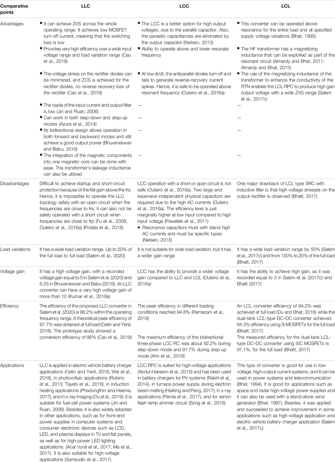
TABLE 1. A comparison between the most common three-element topology (LLC, LCC, and LCL).
3 Resonant Power Converters for Renewable Energy Sources
Some of the applications of RPCs include grid-connected renewable energy converters such as solar, fuel cells, wind, and electric vehicle charging systems via wired or wireless power transfer. The integration of RES to grid requires high-efficiency converters with little current ripple. The fundamental requirement for power processing from RES is DC–DC converters. Among the various options for the DC–DC converter, RPCs can be a major contender due to their high efficiency and power density that can be achieved via SS at the high operating frequencies, low MI, and robustness (Outeiro et al., 2016b; Salem et al., 2018). As a result, RPCs are mostly used in PV systems (PVS), wind energy conversion systems (WECS), fuel cell systems (FCS), and grid connection interfaces.
3.1 Wind Energy Conversion Systems
The study by Fan et al. (2013) compared the performance of LCC RPC with that of the hard-switched full-bridge converter (HSFB) as a linkage to a wind energy electrical source (WECS). The study found the LCC RPC to be more efficient at above half load condition than the HSFB converter. The possibility of using an LCC RPC for WECS is demonstrated by the achieved experimental data. Another study by Moury and Lam (2015) proposed two modular MV step-up DC–DC converters for MVDC grid in wind energy systems; the system incorporates numerous modules of step-up resonant circuits and high-gain, high-frequency rectifiers. The suggested converters demonstrate the ability to obtain substantial voltage gain with a high-frequency transformer with a unity turn ratio while minimizing the power switch-related voltage stress. A highly efficient solution was proposed by Dincan et al. (2019) for wind turbines linked to MVDC networks; the primary side of the proposed system has SRC with LC tank. The architecture was proposed as a unique solution for DC–DC topologies with medium frequency, high voltage gain, and high power. The study by Shu et al. (2017) presented a system for offshore wind farm distribution that consisted of two transformers (one main and one auxiliary), two full-bridge inverters that share a bridge leg, and a voltage-doubler rectifier. A prototype was developed and used to demonstrate the design and working principle of the proposed converter. The SRC proposed by Dincan et al. (2018) has a resonant tank on the high-voltage side; the system was proposed as a solution for high-voltage DC wind turbines; the low transformer size and its high efficiency allow the control of the output power and improve efficiency.
3.2 Fuel Cells
This technology is chosen because of the benefits associated with resonant conversion, notably the minimization of switching losses. The inverter’s turn-on losses are low because the switches are ZVS switched on. As a result, the switch off and conduction losses are considered for each IGBT; these were 23 W at full load and 17 W at 25% of the condition for the employed topology (Salem et al., 2022). The study by Outeiro and Carvalho (2013) presents a concept for the design of a DC–DC RPC for use in PEM fuel cell systems. Another work by Jin and Ruan (2006) describes a unique H-FB TL LLC converter for use in FC power systems. The suggested converter exhibited a high efficiency over a broad range of input voltage, as well as a low input current ripple and an output filter. The use of an LLC RPC in a FC-based power system was presented by Boscaino et al. (2014); the system can be used in FC automobiles. The entire system exhibited excellent conversion efficiency due to the SS features of LLC RPC. In the work by Buccella et al. (2015), a nonlinear LLC RPC model was proposed in combination with an observer-based controller. The output stabilizing capability of the proposed system was demonstrated over a range of load variations; the system was found better than the conventional PID controller.
3.3 Electric Vehicles
RPCs are widely used in electric and hybrid electric vehicle (HEV) charging systems that require wired or wireless charging of the batteries. Wired EVs charging (Fang et al., 2015) and plugged-in EVs (Deng et al., 2014) require the introduction of RPCs to reduce size and achieve high efficiency. The study by Musavi et al. (2013) proposed a high-performance (H-P) LLC converter for use in a 2-stage battery charging system. The converter eliminates the low- and high-frequency ripple on the battery, thereby improving the battery life without expanding the charger’s size. Different studies (Hua et al., 2016; Dalala et al., 2018; Kim et al., 2019; Subramaniam et al., 2019) have suggested other topologies that utilize RPCs for wired charging systems. In order to minimize costs while increasing vehicle performance, high-efficiency and high-power density battery charger designs are becoming increasingly critical in EVs (Emadi et al., 2008) for the improvement of vehicle performance and reduction of cost (Yilmaz and Krein, 2013). The on-board battery charger’s design allows the possibility of charging the battery of vehicles from any power outlet. This end-user flexibility has encouraged interest in EVs (Whitaker et al., 2014). The optimization of the operation region of an LLC RPC for on-board battery charging system has been assessed in Cetin and Yenil (2018). The design optimization considers a wide range of load conditions and output voltage regulation, both of which are necessary for lithium-ion battery charging applications. At full load, the theoretical peak efficiency of the system was approximately 97.7%. There are numerous DC–DC RPCs for on-board battery charging systems in EVs (Lee, 2015; Çetin, 2017; Shen et al., 2018). Another charging system for electric and HEVs is the wireless power transfer (WPT) method, which has become an alternative to wired charging systems (Kan et al., 2017). The currently existing WPT systems are those for electric, electromagnetic, and magnetic power transfer. For the magnetic coupling system, RPCs are used to achieve high power transmission and maximum efficiency at close distance. Studies have documented the use of RPCs in WPT for EVs and HEVs (Li et al., 2015; Samanta and Rathore, 2015; Na et al., 2019).
3.4 Induction Heating
The popularity of RPCs for IH has increased tremendously due to its efficiency, quick heating, precise power control, and safety compared to the conventional heating systems. RPCs are the main component for achieving the expected performance in such systems (Salem et al., 2018). For this purpose, half-bridge, full-bridge, and multi-inverter have been utilized as resonant inverters. The study by Haema and Phadungthin (2018) suggests the creation of an LLC resonant inverter (RI) for use in saw blade induction heating. The use of half bridge RI in the saw blade IH application is aimed at the provision of good power supply for IH, with suitable output power and great efficiency. The development of a high-frequency full-bridge series RI for use in induction-heating cooking equipment has been described by Bhaskar and Vishwanathan (2012). The system is simple in design and operation, and it is also quite inexpensive. The work of researchers in Kumar et al. (2018b) proposed a full-bridge parallel RI (FBPRI) for industrial IH applications that improves the performance and efficiency of the traditional IH systems using a pulse density modulation (PDM) technology. The suggested technique ensures the achievement of ZVS/ZCS condition and lower switching losses under various loads. In the IH system described in Neogi et al. (2019), a high-frequency series RI (HFSRI) was used. The reliability of the proposed system was validated through a stability study of the high-frequency inverter circuit that forms the core of the IH system. It was proven that systems with higher stability are more reliable. A multiphase RI with vertical coupled coils was presented by Gomes et al. (2020) for use in IH systems; the phase-shift control strategy of the proposed system improves the power capability of the system.
3.5 Photovoltaic Systems
The RPCs are widely used in PVs due to their high power density and efficiency. The SS techniques in such systems reduce the switching losses significantly (Outeiro et al., 2016b). In Ragab et al. (2017), a full-bridge LLC RPC has been proposed for a grid-connected double-stage photovoltaic (PV) system to step up the output voltage of the PV array. The proposed converter has the advantages of wide input regulation capability and SS, which allows for high-frequency and high-efficiency operation compared to traditional isolated converters. A half-bridge series-parallel RPC (HBSPRPC) was proposed by Rakhi et al. (2014) for a PV system and secondary battery interface. The design of the converter was aimed at keeping the battery free of high- and low-frequency current ripples. A study by Vakacharla and Rathore (2019) presented a stand-alone SS current-fed LCC-T RPC for the PV/FC system. The suggested converter can achieve SS over a great range of input and load variations, higher gain, continuous input current with minimum ripples, lower harmonic content, higher efficiency, and higher power density. In LaBella and Lai (2014), a novel isolated hybrid RPC was presented for PV applications with numerous operating modes (Buck, pure series resonant RC, and boost mode); these modes were implemented using a simple topology with few components. The power conversion efficiency of the proposed converter is high over a wide range of input-voltage and output-power. Several RPC topologies for grid-linked PV systems have been proposed in Zhao et al. (2017b), Altin et al. (2019), Jean-Pierre et al. (2019), and Tayebi et al. (2019).
3.6 Some Recently Proposed Resonant Topologies for RESs
Independent converters have the primary function of maximizing power extraction from renewable energy sources (such as wind or solar) under varying environmental conditions. Multi-input converters have been proposed to reduce the required number of components via sharing the output stage of many converters. However, under specific load levels, most of the works provided mostly lose soft-switching functions in the power switches. Hence, an asymmetrical PWM (APWM) multi-input isolated RC is presented for a 1-kW PV-wind integrated system by Jean-Pierre et al. (2019) (see Figure 11); the aim of this proposal is to realize soft-switching for varying load circumstances, as well as to offer isolation in the power electronics interface.
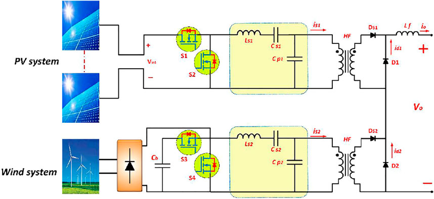
FIGURE 11. Multi-input LLC isolated resonant converter for hybrid wind–solar energy system (Lam and Jain, 2014).
Each module has an APWM LCC resonant isolated converter with a series resonant capacitor (Cs) and a series resonant inductor as its input stage (Ls). High-frequency rectification is provided by two diodes (Ds1 and Ds2) at the output of the high-frequency transformer. In each module, the parallel diode and the output inductor (Lf) are shared between all the input modules, with Lo operating in continuous conduction mode (CCM) to supply steady current to the output. This converter ensures individual and simultaneous activity of the input sources, but this is dependent on the source availability. To achieve ZVS turn-on in all switches, the LCC resonant circuit must be driven above resonance in each module. The turn-off switching losses can be reduced by adding a tiny snubber capacitor across each switch. The connection of an AC input (single-phase or three-phase) to an AC voltage normally requires the inclusion of a power factor correction (PFC) front-end stage to reduce the input-sourced current harmonics. On the other hand, the two-stage method tends to increase the number of controllers, the overall number of circuit components, and the circuit cost. The connection of the input module to an AC voltage demands the integration of the APWM RC in each module with the front-end PFC converter using switch M4, which is shared by the APWM RC and PFC stage. The testing and verification of the system was verified and tested with a switching frequency of 70 kHz and a voltage output of 100 V. To simulate five series-connected solar panels, the converter’s first module was connected to a 175-V DC source (each 35 V). A 1-kW permanent magnet generator with a 300-V rated voltage was connected to the second module. At full load, the converter achieved 92.2% conversion, and at 20%, it achieved 89.6%.
For multi-energy integration systems, bidirectional RCs are considered a better option. Examples of this configuration include battery storage, UPS, motor drives, and vehicle to grid (V2G) applications. Their performance in high-frequency solid-state transformers is also satisfactory. To expand the number of connected devices using a single converter, several upgrades and modifications have been made. Multiport converter topologies have been developed as a result of this demand. Several RC configurations have been integrated with PV systems and battery storage as multiport structures. The study by Lam and Jain (2014) described a half-bridge LLC RC in which two inputs are coupled to one PV and one battery storage system. A non-isolated resonant multiport switching capacitor was presented by Nasiri and Jean-Pierre (2020) for renewable energy and battery storage.
Figure 12 shows a multiport RC design with a PV system, battery energy storage, and utility grid as the three primary components. A common DC bus Vdc is shared between the PV and battery energy storage systems; it serves as the input or output of the RC depending on the operation mode. The configuration of the battery energy storage was done using a bidirectional buck-boost converter that is connected in parallel to the PV; this configuration forms the two bidirectional converter ports at node A. Through the voltage source inverter, the utility grid serves as the other port of the converter. The high-frequency transformer transports power from node A to node B. The renewable energy source is designated by the letterVpv, which stands for the PV system’s voltage. The input capacitor is Cpv, the battery storage voltage is Vbat, and the bidirectional buck-boost converter’s inductance is Lbat. Vdc and Vo can be used as either the input or output DC voltage of the LLC RC based on the operating mode. Cdc and Co constitute the DC bus capacitor. To obtain the MPPT, the current in the energy storage system of the battery is regulated. The grid-connected 3-phase voltage source inverter may transmit power either from the PV and battery storage to the grid or from the grid to the battery storage. The power can come from a combination of solar panels, battery storage, and/or the grid. As a result, this converter arrangement can operate in two different modes: forward and backward. The validation of the system was done using LLC RC, Buck-Boost converter, and voltage source inverter (VSI) with switching frequencies of 20–60, 30, and 10 kHz, respectively; the grid voltage and frequency of Vg, fg 230 V/50 Hz were also utilized. A stable power flow was maintained between the ports; the main voltage values at each port was kept constant regardless of the operation mode. This system can use only one transformer to combine two sources and offer galvanic isolation to the grid (Namadmalan et al., 2020).
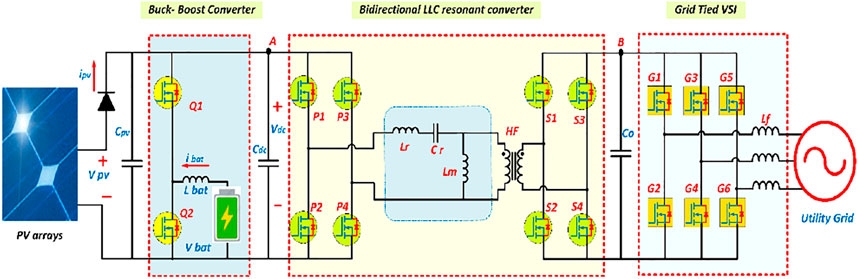
FIGURE 12. Multi-port LLC resonant converter for PV, ES, and utility grid integration (Nasiri and Jean-Pierre, 2020).
A dual-active bridge SRC (DAB-SRC) is a common structure for the regulation of bidirectional power flow in high-power devices such as fast charging of EVs (Kala et al., 2017). Figure 13 depicts an EV charging stage using DAB-SRCs to enable V2G bidirectional power flow capability (Jebaselvi et al., 2013). DAB-SRC also has the advantage of being able to be deployed in a modular framework without the requirement for additional input or output filters.
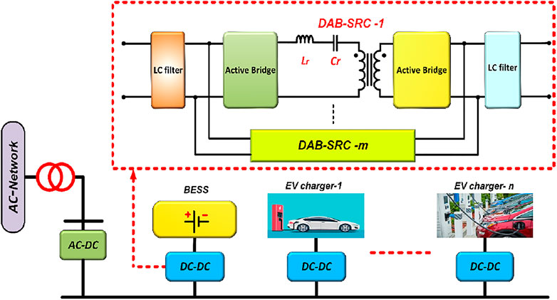
FIGURE 13. An electric vehicle (EV) charging station with n-number of charging stages and m-number of paralleled DAB-SRCs (Namadmalan et al., 2020).
This approach has the major problem of tuning the power and frequency of the power converters using minimum phase displacement or circulating current (Lin and Chu, 2016). This problem was addressed by proposing a self-tuning approach with fast dynamics and no tolerance sensitivity. This approach was used recently to tune the power and frequency of wireless charging of EVs using the IPT technology [137]. The study by Jin et al. (2014) relied on the self-tuning loop’s parameters to obtain the design parameters for the DAB-SRC, such as DC-link voltages, minimum and maximum transferred power, switching frequency bandwidth, and temporal displacement between the two active bridges. This basic design increased the performance of bidirectional DAB-SRCs utilizing the self-tuning approach; this is due to the establishment of an intrinsically constant time delay between the two active bridges from light load to full load; hence, ZVS was obtained for all the switches.
The depiction of the fast charger system is shown in Figure 14. AC/DC rectifier, full-bridge LLC RC, and a light electric vehicle (LEV) battery. The DSP (TMS320F28335) was utilized to control and sense the system voltage and current in the fast charger. The MOSFET gate (Dalala et al., 2018) is the switching component of the LLC converter. The switching stress can be reduced by adopting a soft start to lower the inrush current at the initial start. System control was achieved using pulse frequency modulation (PFM) and PI control. A different control mechanism for lowering charging time is required in the case of an LEV battery with LIB and SC. This system’s input and output voltages are roughly 250–300 VAC (voltage alternating current) and 25.6–33.6 VDC (voltage direct current), respectively. The SC output voltage is approximately 048 V while the control current for the system is 30 A.
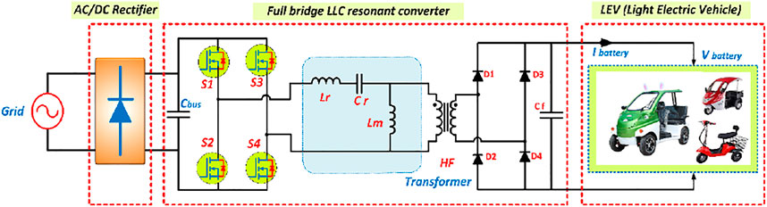
FIGURE 14. The fast charger for light electric vehicle LEV using an LLC resonant converter (Kim et al., 2019).
In the ZVS region, this fast-charging device uses an LLC RC with SS features. Air and environmental pollutants have reduced the use of lead-acid batteries. Hence, this LEV system with a Li-ion battery (LIB) of 800 Wh and SC of 50 Wh is considered a fast-charging scheme as the charging time is about 1 h. Furthermore, in the CC mode, the highest output current (30 A) conversion efficiency was 96.4%.
4 Challenges and Future Work Recommendations
The rapid growth of power electronics devices and technology has increased the application of RES in power grid. This has led to concerns about the power quality, intermittent nature, reliability, and protection of energy transmitted to the grid. As a result, many grid regulations and standards exist for grid-connected RES to preserve grid power quality (Jebaselvi et al., 2013; Kala et al., 2017). From the present literature review, some research areas, and future challenges in the PRCs and their renewable energy systems (RESs) applications are highlighted:
• The intermittent nature of the power provided by grid-connected RES is one of the major challenges. The worldwide energy share of renewables is expected to rise even further in the future. As a result, researchers should pay more attention to the issue of injected power fluctuations in the grid.
• RPCs have found wide application in various power conversion systems recently. This is mostly owing to its attractive features, such as higher power density and efficiency in comparison to traditional PWM converters. However, there are still a number of issues and research challenges in the field of RPCs that must be addressed to improve their performance. It may require making modifications either on the circuit design or control strategy to eliminate them, and thus improve the performance of these converters.
• The LLC RPC is a promising converter and has several advantages that enable it to perform better than other RPC topologies. As a result, it has become a popular power source for a variety of applications. The LLC RPC, however, has a number of challenges, including start-up, SR driving mechanism, short-circuit protection, magnetic design, and EMI noise reduction (Huang, 2014; Outeiro et al., 2016a; Outeiro et al., 2016b; Cao et al., 2018; Rusu et al., 2019). This necessitates further investigation.
• High-voltage systems are better operated using multi-phase and multi-level RPCs. However, when compared to SLCs, there are notable restrictions, such as output current imbalances between phases, difficulty in the analysis of the control systems and operating modes, as well as the need for numerous electromagnetic components and switching devices. As a result, they have become unworkable in terms of size and cost (Jin et al., 2014; Lin and Chu, 2016; Salem et al., 2018).
5 Conclusion
RPCs have been investigated in many aspects in this paper; this review covered the significant development of RPCs as a solution to the problems of EMI and switching losses. Resonant converters were also classified from numerous perspectives in this review. In addition, the highlighted topologies were compared in various aspects such as merits, drawbacks, and efficiency. In terms of applications, this article focused on renewable energy systems that utilized RPC. This review also covered most of the notable studies on RPCs, which have been utilized in renewable energy sources, with the hope of providing insight into the current challenges of RPCs in renewable energy applications.
Author Contributions
AB and MS contributed to design and conceptualization and writing. MA contributed to editing and writing some parts of the work. DI, MK, and SA contributed to writing, analysis, and editing.
Conflict of Interest
The authors declare that the research was conducted in the absence of any commercial or financial relationships that could be construed as a potential conflict of interest.
Publisher’s Note
All claims expressed in this article are solely those of the authors and do not necessarily represent those of their affiliated organizations, or those of the publisher, the editors, and the reviewers. Any product that may be evaluated in this article, or claim that may be made by its manufacturer, is not guaranteed or endorsed by the publisher.
Acknowledgments
The authors would like to pay gratitude to Universiti Sains Malaysia for support under the Short-term grant No. 304/PELECT/6315330 and library facilities. Lastly, thanks to those colleagues who have either directly or indirectly contributed to the completion of this work.
Abbreviations
Ac, a capacitance ratio; AL, an inductance ratio; rs, frp, series/parallel resonant frequency; fs, switching frequency; fr, resonant frequency; MV, voltage gain; Q, quality factor; Re, effective load resistance seen by RTN; Zi, RTN input impedance; is, RTN input current; ir, rectifier input current; EMI, electromagnetic interferences; RI, resonant inverter; Vs, RTN input voltage; Vr, rectifier input voltage; PF, power factor; SS, soft switching; Ws, angular frequency; ZVS, zero-voltage switching; ZCS, zero-current switching.
References
Abdul-Hakeem, M. D., Sahid, M. R., and Sutikno, T. (2018). Overview of Soft-Switching DC-DC Converters. Power Electron. 9 (4), 2006. doi:10.11591/ijpeds.v9.i4.pp2006-2018
Acar Vural, R., Demirel, İ., and Erkmen, B. (2017). Design and Optimization of a Power Supply Unit for Low Profile LCD/LED TVs. Int. J. Optim. Control Theor. Appl. (Ijocta) 7 (2), 158–166. doi:10.11121/ijocta.01.2017.00440
Ahn, S.-H., Jang, S.-R., and Ryoo, H.-J. (2019). High-Efficiency Bidirectional Three-phase LCC Resonant Converter with a Wide Load Range. IEEE Trans. Power Electron. 34 (1), 97–105. doi:10.1109/tpel.2018.2815078
Alatai, S., Salem, M., Ishak, D., Kamarol, M., Jamil, M., and Bughneda, A. (2020). “Design and Analysis of Five-Level Cascaded LLC Resonant Converter,” in 2020 IEEE International Conference on Power and Energy (PECon) (IEEE), 66–70. doi:10.1109/pecon48942.2020.9314463
Alatai, S., Salem, M., Ishak, D., Das, H. S., Alhuyi Nazari, M., Bughneda, A., et al. (2021). A Review on State-Of-The-Art Power Converters: Bidirectional, Resonant, Multilevel Converters and Their Derivatives. Appl. Sci. 11 (21), 10172. doi:10.3390/app112110172
Almardy, M., and Bhat, A. (2015). “A Comparison of Three-phase High-Frequency Transformer Isolated LCC and LCL-type DC-DC Resonant Converter Topologies,” in 2015 9th International Conference on Power Electronics and ECCE Asia (ICPE-ECCE Asia) (IEEE). doi:10.1109/icpe.2015.7167979
Almardy, M., and Bhat, A. K. S. (2019). Three‐phase Fixed‐frequency Interleaved (LC)(L)‐type Series‐resonant Converter with a Capacitive Output Filter. J. Eng. 2019 (17), 4178–4184. doi:10.1049/joe.2018.8073
Almardy, M. S., and Bhat, A. K. S. (2011). Three-phase (LC)(L)-type Series-Resonant Converter with Capacitive Output Filter. IEEE Trans. Power Electron. 26 (4), 1172–1183. doi:10.1109/tpel.2010.2076365
Altin, N., Ozdemir, S., and Nasiri, A. (2019). “A Novel Solar PV Inverter Topology Based on an LLC Resonant Converter,” in 2019 IEEE Energy Conversion Congress and Exposition (ECCE). doi:10.1109/ecce.2019.8912924
Ang, Y.-A. (2006). Modelling, Analysis and Design of LCLC Resonant Power Converters. Sheffield, England: University of Sheffield.
Azura, N., Iqbal, S., and Taib, S. (2014). “LLC Resonant DC-DC Converter for High Voltage Applications,” in 2014 IEEE Conference on Energy Conversion (CENCON) (IEEE). doi:10.1109/cencon.2014.6967482
Batarseh, I. (1994). Resonant Converter Topologies with Three and Four Energy Storage Elements. IEEE Trans. Power Electron. 9 (1), 64–73. doi:10.1109/63.285495
Beiranvand, R., Rashidian, B., Zolghadri, M. R., and Alavi, S. M. H. (2011). Using LLC Resonant Converter for Designing Wide-Range Voltage Source. IEEE Trans. Ind. Electron. 58 (5), 1746–1756. doi:10.1109/tie.2010.2052537
Bhaskar, D. V., and Vishwanathan, N. (2012). “Full Bridge Series Resonant Inverter for Induction Cooking Application,” in 2012 IEEE 5th India International Conference on Power Electronics (IICPE) (IEEE). doi:10.1109/iicpe.2012.6450370
Bhat, A. K. S. (1995). A Fixed-Frequency Modified Series-Resonant Converter: Analysis, Design, and Experimental Results. IEEE Trans. Power Electron. 10 (6), 766–775. doi:10.1109/63.471297
Bhat, A. K. S. (1997). Analysis and Design of a Fixed-Frequency LCL-type Series-Resonant Converter with Capacitive Output Filter. IEE Proc. Circuits Devices Syst. 144 (2), 97–103. doi:10.1049/ip-cds:19970873
Bhat, A. K. S. (1994). Analysis and Design of LCL-type Series Resonant Converter. IEEE Trans. Ind. Electron. 41 (1), 118–124. doi:10.1109/41.281617
Bhatt, N. (2017). A Dual Tank High Frequency Isolated LCL Series Resonant Converter: Design, Simulation, and Experimental Results.
Bhuvaneswari, C., and Babu, R. S. R. (2016). “A Review on LLC Resonant Converter,” in 2016 International Conference on Computation of Power, Energy Information and Commuincation (ICCPEIC) (IEEE). doi:10.1109/iccpeic.2016.7557268
Bhuvaneswari, C., Babu, R. S., and Systems, D. (2018). Analysis of High Voltage High Power Resonant Converters. Int. J. Power Electron. Drive Syst. 9 (1), 174.
Boscaino, V., Miceli, R., Buccella, C., Cecati, C., Latafat, H., Razi, K., et al. (2014). “Fuel Cell Power System with LLC Resonant DC/DC Converter,” in 2014 IEEE International Electric Vehicle Conference (IEVC) (IEEE), 1–6. doi:10.1109/ievc.2014.7056220
Buccella, C., Cecati, C., Latafat, H., Pepe, P., and Razi, K. (2015). Observer-Based Control of LLC DC/DC Resonant Converter Using Extended Describing Functions. IEEE Trans. Power Electron. 30 (10), 5881–5891. doi:10.1109/tpel.2014.2371137
Cao, Q., Li, Z., and Wang, H. (2018). “Wide Voltage Gain Range LLC DC/DC Topologies: State-Of-The-Art,” in 2018 International Power Electronics Conference (IPEC-Niigata 2018-ECCE Asia) (IEEE). doi:10.23919/ipec.2018.8507899
Cao, S., Zhang, Y., and Zheng, C. (2019). “High Efficiency LLC Converter Design Using a Novel Modelling Method Based on SiC MOSFET,” in 2019 22nd International Conference on Electrical Machines and Systems (ICEMS) (IEEE). doi:10.1109/icems.2019.8921615
Çetin, S. (2017). High Efficiency Design Approach of a LLC Resonant Converter for On-Board Electrical Vehicle Battery Charge Applications. Pamukkale J. Eng. Sci. 23 (2), 103–111. doi:10.5505/pajes.2016.56198
Cetin, S., and Yenil, V. (2018). “Optimal Operation Region of LLC Resonant Converter for On-Board EV Battery Charger Applications,” in 2018 IEEE 18th International Power Electronics and Motion Control Conference (PEMC) (IEEE). doi:10.1109/epepemc.2018.8521857
Chen, Y., Xu, J., Gao, Y., Lin, L., Cao, J., and Ma, H. (2020). Analysis and Design of Phase-Shift Pulse-Frequency-Modulated Full-Bridge LCC Resonant Converter. IEEE Trans. Ind. Electron. 67 (2), 1092–1102. doi:10.1109/tie.2019.2898586
Chien, C. H., Wang, Y. H., and Lin, B. R. (2013). Analysis of a Novel Resonant Converter with Series Connected Transformers. IET Power Electron. 6 (3), 611–623. doi:10.1049/iet-pel.2012.0358
Colak, K., Asa, E., and Czarkowski, D. (2015). “A Comparison Analysis of CLL and LLC Resonant Converter for Multi-phase Applications,” in 2015 IEEE Transportation Electrification Conference and Expo (ITEC) (IEEE). doi:10.1109/itec.2015.7165757
Conesa, A., Velasco, G., Martínez, H., and Román, M. (2009). “LCLC Resonant Converter as Maximum Power point Tracker in PV Systems,” in 2009 13th European Conference on Power Electronics and Applications (IEEE), 1–9.
Dalala, Z. M., Zahid, Z. U., Saadeh, O. S., and Lai, J.-S. (2018). Modeling and Controller Design of a Bidirectional Resonant Converter Battery Charger. IEEE Access 6, 23338–23350. doi:10.1109/access.2018.2830321
Deepika, G., and Elakkiya, M. (2014). Comparison of LLC and LCC Resonant Converter Using Conventional and FUZZY Controller.
Deng, J., Li, S., Hu, S., Mi, C. C., and Ma, R. (2014). Design Methodology of LLC Resonant Converters for Electric Vehicle Battery Chargers. IEEE Trans. Veh. Technol. 63 (4), 1581–1592. doi:10.1109/tvt.2013.2287379
Deshmukh, S., Iqbal, A., Islam, S., Khan, I., Marzband, M., Rahman, S., et al. (2022). Review on Classification of Resonant Converters for Electric Vehicle Application. Energ. Rep. 8, 1091–1113. doi:10.1016/j.egyr.2021.12.013
Dincan, C. G., Kjaer, P., Chen, Y.-H., Sarra-Macia, E., Munk-Nielsen, S., Bak, C. L., et al. (2019). Design of a High-Power Resonant Converter for DC Wind Turbines. IEEE Trans. Power Electron. 34 (7), 6136–6154. doi:10.1109/tpel.2018.2876320
Dincan, C., Kjaer, P., Chen, Y.-h., Munk-Nielsen, S., and Bak, C. L. (2018). Analysis of a High-Power, Resonant DC-DC Converter for DC Wind Turbines. IEEE Trans. Power Electron. 33 (9), 7438–7454. doi:10.1109/tpel.2017.2770322
Dobrucky, B., and Koscelnik, J. J. P. (2005). Multi-element Circuits Based on LCLC Resonant Tank-Theory and Application. IEEE Trans. Power Electron. 10, 20.
Du, Y., and Bhat, A. K. S. (2016). Analysis and Design of a High-Frequency Isolated Dual-Tank $LCL$ Resonant AC–DC Converter. IEEE Trans. Industry Appl. 52 (2), 1566–1576.
Emadi, A., Lee, Y. J., and Rajashekara, K. (2008). Power Electronics and Motor Drives in Electric, Hybrid Electric, and Plug-In Hybrid Electric Vehicles. IEEE Trans. Ind. Electron. 55 (6), 2237–2245. doi:10.1109/tie.2008.922768
Fan, S., Ma, W., Lim, T. C., and Williams, B. W. (2013). Design and Control of a Wind Energy Conversion System Based on a Resonant Dc/dc Converter. IET Renew. Power Generation 7 (3), 265–274. doi:10.1049/iet-rpg.2012.0069
Fang, Z., Cai, T., Duan, S., and Chen, C. (2015). Optimal Design Methodology for LLC Resonant Converter in Battery Charging Applications Based on Time-Weighted Average Efficiency. IEEE Trans. Power Electron. 30 (10), 5469–5483. doi:10.1109/tpel.2014.2379278
Fei, C. (2018). Optimization of LLC Resonant Converters: State-Trajectory Control and PCB Based Magnetics. Blacksburg, VA: Virginia Tech.
Fu, D., Lee, F. C., Liu, Y., and Xu, M. (2008). “Novel Multi-Element Resonant Converters for Front-End Dc/dc Converters,” in 2008 IEEE Power Electronics Specialists Conference (IEEE), 250–256. doi:10.1109/pesc.2008.4591934
Gautam, D., and Bhat, A. K. (2012). “An Integrated Boost-Dual Half-Bridge LCL SRC with Capacitive Output Filter for Electrolyser Application,” in IECON 2012-38th Annual Conference on IEEE Industrial Electronics Society (IEEE). doi:10.1109/iecon.2012.6389356
Geetha, V., Sivachidambaranathan, V., and Systems, D. (2018). A Single Switch Parallel Quasi Resonant Converter Topology for Induction Heating Application. Ijpeds 9 (4), 1718. doi:10.11591/ijpeds.v9.i4.pp1718-1724
Gomes, R. C. M., Vitorino, M. A., Acevedo-Bueno, D. A., and Correa, M. B. d. R. (2020). Multiphase Resonant Inverter with Coupled Coils for AC-AC Induction Heating Application. IEEE Trans. Ind. Applicat. 56 (1), 551–560. doi:10.1109/tia.2019.2955661
Haema, J., and Phadungthin, R. (2018). “Development of LLC Resonant Inverter for Saw Blade Induction Heating Applications,” in 2018 5th International Conference on Electric Power and Energy Conversion Systems (EPECS) (IEEE). doi:10.1109/epecs.2018.8443350
Haifeng, Z., and Peng, W. (2017). Design of an LCC Resonant Converter for Furnace Power Supply during Electron Bean Melting. IEEJ J. IA 6 (6), 387–394. doi:10.1541/ieejjia.6.387
Harischandrappa, N., and Bhat, A. K. S. (2014). A Fixed-Frequency $LCL$-Type Series Resonant Converter with a Capacitive Output Filter Using a Modified Gating Scheme. IEEE Trans. Ind. Applicat. 50 (6), 4056–4064. doi:10.1109/tia.2014.2323471
Hua, C. C., Fang, Y. H., and Lin, C. W. (2016). LLC Resonant Converter for Electric Vehicle Battery Chargers. IET Power Electron. 9 (12), 2369–2376. doi:10.1049/iet-pel.2016.0066
Huang, D. (2014). Investigation of Topology and Integration for Multi-Element Resonant Converters. Blacksburg, VA: Virginia Tech.
Huang, D., Lee, F. C., and Fu, D. (2011). “Classification and Selection Methodology for Multi-Element Resonant Converters,” in 2011 Twenty-Sixth Annual IEEE Applied Power Electronics Conference and Exposition (APEC) (IEEE). doi:10.1109/apec.2011.5744651
Huang, H. (2010). “Designing an LLC Resonant Half-Bridge Power Converter,” in 2010 Texas Instruments Power Supply Design Seminar, SEM1900, Topic.
Huang, Y.-H., Liang, T.-J., and Wu, W.-J. (2016). “Analysis and Implementation of Half-Bridge Resonant Capacitance LLC Converter,” in 2016 IEEE International Conference on Industrial Technology (ICIT) (IEEE). doi:10.1109/icit.2016.7474943
Ibanez, F. M., Echeverria, J. M., Vadillo, J., and Fontan, L. (2015). A Step-Up Bidirectional Series Resonant DC/DC Converter Using a Continuous Current Mode. IEEE Trans. Power Electron. 30 (3), 1393–1402. doi:10.1109/tpel.2014.2318202
Jean-Pierre, G., El Shafei, A., Altin, N., and Nasiri, A. (2019). “A Multiport Bidirectional LLC Resonant Converter for Grid-Tied Photovoltaic-Battery Hybrid System,” in 2019 8th International Conference on Renewable Energy Research and Applications (ICRERA), 755–760. IEEE. doi:10.1109/icrera47325.2019.8996775
Jebaselvi, G. D. A., Paramasivam, S., and Reviews, S. E. (2013). Analysis on Renewable Energy Systems. Renew. Sustain. Energ. Rev. 28, 625–634. doi:10.1016/j.rser.2013.07.033
Jin, F., Liu, F., Ruan, X., and Meng, X. (2014). “Multi-phase Multi-Level LLC Resonant Converter with Low Voltage Stress on the Primary-Side Switches,” in 2014 IEEE Energy Conversion Congress and Exposition (ECCE) (IEEE), 4704–4710. doi:10.1109/ecce.2014.6954045
Jin, K., and Ruan, X. (2006). Hybrid Full-Bridge Three-Level LLC Resonant Converter-A Novel DC-DC Converter Suitable for Fuel-Cell Power System. IEEE Trans. Ind. Electron. 53 (5), 1492–1503. doi:10.1109/tie.2006.882020
Kala, P., Arora, S., and Reviews, S. E. (2017). A Comprehensive Study of Classical and Hybrid Multilevel Inverter Topologies for Renewable Energy Applications. Renew. Sustain. Energ. Rev. 76, 905–931. doi:10.1016/j.rser.2017.02.008
Kan, T., Nguyen, T.-D., White, J. C., Malhan, R. K., and Mi, C. C. (2017). A New Integration Method for an Electric Vehicle Wireless Charging System Using LCC Compensation Topology: Analysis and Design. IEEE Trans. Power Electron. 32 (2), 1638–1650. doi:10.1109/tpel.2016.2552060
Kim, D.-H., Kim, M.-S., Hussain Nengroo, S., Kim, C.-H., and Kim, H.-J. (2019). LLC Resonant Converter for LEV (Light Electric Vehicle) Fast Chargers. Electronics 8 (3), 362. doi:10.3390/electronics8030362
Koscelnik, J., Frivaldsky, M., Prazenica, M., and Mazgut, R. (2014). “A Review of Multi-Elements Resonant Converters Topologies,” in 2014 ELEKTRO. IEEE, 312–317. doi:10.1109/elektro.2014.6848909
Kumar, A., Sadhu, P. K., Raman, R., and Singh, J. (2018). “Design Analysis of Full-Bridge Parallel Resonant Inverter for Induction Heating Application Using Pulse Density Modulation Technique,” in 2018 International Conference on Power Energy, Environment and Intelligent Control (PEEIC). (IEEE), 398–402. doi:10.1109/peeic.2018.8665571
Kumar, A., Singh, R. K., and Naick, B. K. (2018). “A Highly Efficient PV and Fuel Cell Powered Full Bridge Bidirectional LLC Resonant Converter,” in 2018 International Electrical Engineering Congress (iEECON) (IEEE). doi:10.1109/ieecon.2018.8712288
LaBella, T., and Lai, J.-S. (2014). A Hybrid Resonant Converter Utilizing a Bidirectional GaN AC Switch for High-Efficiency PV Applications. IEEE Trans. Ind. Applicat. 50 (5), 3468–3475. doi:10.1109/tia.2014.2312818
Lam, J., and Jain, P. K. (2014). “An Asymmetrical PWM (APWM) Controlled Multi-Input Isolated Resonant Converter with Zero Voltage Switching (ZVS) for Hybrid Renewable Energy Systems,” in 2014 IEEE 36th International Telecommunications Energy Conference (INTELEC) (IEEE). doi:10.1109/intlec.2014.6972220
Lee, I.-O. (2015). Hybrid PWM-Resonant Converter for Electric Vehicle On-Board Battery Chargers. IEEE Trans. Power Electron. 31 (5), 3639–3649.
Lee, I.-O., and Moon, G.-W. (2011). “Three-level LLC SRC for High and Wide Input Voltage Applications,” in 8th International Conference on Power Electronics-ECCE Asia (IEEE). doi:10.1109/icpe.2011.5944542
Li, W., Zhao, H., Li, S., Deng, J., Kan, T., and Mi, C. C. (2015). Integrated ${LCC} $ Compensation Topology for Wireless Charger in Electric and Plug-In Electric Vehicles. IEEE Trans. Ind. Electron. 62 (7), 4215–4225. doi:10.1109/tie.2014.2384003
Lin, B.-R., and Chu, C.-W. (2016). Hybrid DC-DC Converter with High Efficiency, Wide ZVS Range, and Less Output Inductance. Int. J. Circ. Theor. Appl. 44 (5), 996–1011. doi:10.1002/cta.2119
Lin, B. R., Chen, J. Y., Chiang, H. K., and Chen, C. C. (2013). “Parallel Resonant Converter with Flying Capacitor,” in 2013 IEEE International Conference of IEEE Region 10 (TENCON 2013) (IEEE), 1–6. doi:10.1109/tencon.2013.6718904
Liu, C. (2017). Analysis, Design and Control of DC-DC Resonant Converter for On-Board Bidirectional Battery Charger in Electric Vehicles. Sheffield, England: University of Sheffield.
Liu, F., Chen, Y., and Chen, X. (2017). Comprehensive Analysis of Three-phase Three-Level LC-type Resonant DC/DC Converter with Variable Frequency Control-Series Resonant Converter. IEEE Trans. Power Electron. 32 (7), 5122–5131. doi:10.1109/tpel.2016.2613127
Liu, G. L., Li, X., Wu, L., Li, Z. Y., and Chen, G. Z. (2018). Analysis and Design-Optimization of LCC Resonant Converter Operating under Wide Range Input and Output Voltage. J. Zhejiang Univ. (Engineering Science) 52 (9), 1762–1770. doi:10.3785/j.issn.1008-973X.2018.09.017
Liu, K.-H., Oruganti, R., and Lee, F. C. Y. (1987). Quasi-resonant Converters-Topologies and Characteristics. IEEE Trans. Power Electron. PE-2 (1), 62–71. doi:10.1109/tpel.1987.4766333
Lu, F., Zhang, H., Hofmann, H., and Mi, C. (2015). A Double-Sided LCLC-Compensated Capacitive Power Transfer System for Electric Vehicle Charging. IEEE Trans. Power Electron. 30 (11), 6011–6014. doi:10.1109/tpel.2015.2446891
Ma, W., Xie, X., and Jiang, S. (2017). “LLC Resonant Converter with Variable Resonant Inductor for Wide LED Dimming Range,” in 2017 IEEE Applied Power Electronics Conference and Exposition (APEC) (IEEE). doi:10.1109/apec.2017.7931116
Martinez, W., Cortes, C., Yamamoto, M., and Imaoka, J. (2018). Effect of Inductor Parasitic Resistances on the Voltage Gain of High Step‐up DC-DC Converters for Electric Vehicle Applications. IET Power Electron. 11 (10), 1628–1639. doi:10.1049/iet-pel.2017.0361
Martins, M. L., Russi, J. L., Pinheiro, J. R., and Hey, H. L. (2006). “Novel Resonant Transition PWM Inverters: Synthesis and Analysis,” in 2006 37th IEEE Power Electronics Specialists Conference (IEEE), 1–7. doi:10.1109/pesc.2006.1712179
Moradisizkoohi, H., and Mohammed, O. A. (2017). “A Quasi-Resonant Bi-directional Buck-Boost Converter for Electric Vehicle Applications,” in 2017 IEEE Transportation Electrification Conference and Expo (ITEC) (IEEE). doi:10.1109/itec.2017.7993341
Moury, S., and Lam, J. (2015). “Modular Isolated High Frequency Medium Voltage (MV) Step-Up Resonant DC/DC Converters with High-Gain Rectifier for Wind Energy Systems,” in 2015 IEEE Energy Conversion Congress and Exposition (ECCE) (IEEE). doi:10.1109/ecce.2015.7310336
Musavi, F., Craciun, M., Gautam, D. S., Eberle, W., and Dunford, W. G. (2013). An LLC Resonant DC-DC Converter for Wide Output Voltage Range Battery Charging Applications. IEEE Trans. Power Electron. 28 (12), 5437–5445. doi:10.1109/tpel.2013.2241792
Na, N., Huynh, T., and Badawy, M. O. (2019). “Design of a Feedback Controlled Dual Sided LCC Converter to Achieve ZVS for Electric Vehicle Wireless Charging Applications,” in IECON 2019-45th Annual Conference of the IEEE Industrial Electronics Society (IEEE). doi:10.1109/iecon.2019.8927213
Namadmalan, A., Rouzbehi, K., Escaño, J. M., and Bordons, C. (2020). Dual-Active Bridge Series Resonant Electric Vehicle Charger: A Self-Tuning Method. Electronics 9 (2), 253. doi:10.3390/electronics9020253
Nasiri, A., and Jean-Pierre, G. J. (2020). A Multiport Bidirectional LLC Resonant Converter for Grid-Tied Photovoltaic-Battery Hybrid System. ICRERA 10 (2).
Neogi, K., Sadhu, M., Das, N., Sadhu, P. K., Chakraborty, A., Ganguly, A., et al. (2019). A New Approach for the Stability Analysis of High-Frequency Series Resonant Inverter-Fitted Induction Heater. Ain Shams Eng. J. 10 (1), 185–194. doi:10.1016/j.asej.2018.04.004
Nielsen, R. (2013). LLC and LCC Resonance Converters Properties Analysis Control. Tommerup, Denmark: Runo Nielsen, 1–21.
Ou, Z., Gao, F., Zhao, H., Zhu, L., Dang, S., Hu, Y., et al. (2019). “Design and Analysis of LLC Resonant Converter for X-Ray High-Voltage Power,” in 2019 IEEE 4th Advanced Information Technology, Electronic and Automation Control Conference (IAEAC) (IEEE) 1, 505–510. doi:10.1109/iaeac47372.2019.8997738
Outeiro, M. T., Buja, G., and Carvalho, A. (2014). “Resonant Converters for Electric Equipment Power Supply,” in IECON 2014-40th Annual Conference of the IEEE Industrial Electronics Society (IEEE). doi:10.1109/iecon.2014.7049270
Outeiro, M. T., and Buja, G. (2015). “Comparison of Resonant Power Converters with Two, Three, and Four Energy Storage Elements,” in IECON 2015-41st Annual Conference of the IEEE Industrial Electronics Society (IEEE). doi:10.1109/iecon.2015.7392297
Outeiro, M. T., Buja, G., and Czarkowski, D. (2016). Resonant Power Converters: An Overview with Multiple Elements in the Resonant Tank Network. EEE Ind. Electron. Mag. 10 (2), 21–45. doi:10.1109/mie.2016.2549981
Outeiro, M. T., and Carvalho, A. (2013). “Design, Implementation and Experimental Validation of a DC-DC Resonant Converter for PEM Fuel Cell Applications,” in IECON 2013-39th Annual Conference of the IEEE Industrial Electronics Society (IEEE). doi:10.1109/iecon.2013.6699206
Outeiro, M. T., Suryawanshi, H., and Buja, G. (2016). “Resonant Power Converters Applications: L S C S L P C P Circuit for Renewable Energy Sources as Case Study,” in IECON 2016-42nd Annual Conference of the IEEE Industrial Electronics Society (IEEE).
Pawellek, A., Oeder, C., Stahl, J., and Duerbaum, T. (2011). “The Resonant LLC vs. LCC Converter-Comparing Two Optimized Prototypes,” in 2011 IEEE Energy Conversion Congress and Exposition (IEEE), 2229–2235. doi:10.1109/ecce.2011.6064064
Pernía, A. M., Prieto, M. J., Villegas, P. J., Díaz, J., and Martín-Ramos, J. A. (2017). LCC Resonant Multilevel Converter for X-ray Applications. Energies 10 (10), 1573. doi:10.3390/en10101573
Phadungthin, R., and Haema, J. (2017). “Application Study on Induction Heating Using Half Bridge LLC Resonant Inverter,” in 2017 12th IEEE Conference on Industrial Electronics and Applications (ICIEA) (IEEE). doi:10.1109/iciea.2017.8283090
Pridala, M., Frivaldsky, M., and Ovaska, S. J. (2018). “Comparison of Converters Using LLC and LCCT Resonant Tanks,” in 2018 ELEKTRO (IEEE). doi:10.1109/elektro.2018.8398282
Ragab, A. S., Saad, N. H., and El-Sattar, A. A. (2017). “LLC Resonant DC-DC Converter for Grid-Connected PV System,” in 2017 12th International Conference on Computer Engineering and Systems (ICCES) (IEEE). doi:10.1109/icces.2017.8275318
Rakhi, K., lango, K., Manjunath, H. V., and Nair, M. G. (2014). “Simulation Analysis of Half Bridge Series Parallel Resonant Converter Based Battery Charger for Photovoltaic System,” in 2014 power and energy systems: towards sustainable energy (IEEE), 1–5. doi:10.1109/pestse.2014.6805296
Ramezani, A., Farhangi, S., Iman-Eini, H., Farhangi, B., Rahimi, R., and Moradi, G. R. (2019). Optimized LCC-Series Compensated Resonant Network for Stationary Wireless EV Chargers. IEEE Trans. Ind. Electron. 66 (4), 2756–2765. doi:10.1109/tie.2018.2840502
Rubino, G., Rubino, L., Serbia, N., Ladoux, P., and Marino, P. (2013). “LLC Resonant Converters in PV Applications Comparison of Topologies Considering the Transformer Design,” in 2013 International Conference on Clean Electrical Power (ICCEP) (IEEE), 37–41. doi:10.1109/iccep.2013.6586962
Rusu, A. I., Florescu, A., and Teodorescu, M. S. (2019). “Improved Model of a Standard LLC Resonant Converter Architecture,” in 2019 11th International Symposium on Advanced Topics in Electrical Engineering (ATEE) (IEEE). doi:10.1109/atee.2019.8724860
Saha, T., Wang, H., Riar, B., and Zane, R. (2018). “Analysis and Design of a Parallel Resonant Converter for Constant Current Input to Constant Voltage Output Dc-Dc Converter over Wide Load Range,” in 2018 International Power Electronics Conference (IPEC-Niigata 2018-ECCE Asia) (IEEE), 4074–4079. doi:10.23919/ipec.2018.8507404
Salem, M., SaJusohlem, A., Idris, N. R. N., and Alhamrouni, I. (2017). “Comparison of LCL Resonant Converter with Fixed Frequency, and Variable Frequency Controllers,” in 2017 IEEE Conference on Energy Conversion (CENCON) (IEEE), 84–89. doi:10.1109/cencon.2017.8262463
Salem, M., Ramachandaramurthy, V. K., Sanjeevikumar, P., Leonowicz, Z., and Yaramasu, V. (2019). “Full Bridge LLC Resonant Three-phase Interleaved Multi Converter for HV Applications,” in 2019 IEEE International Conference on Environment and Electrical Engineering and 2019 IEEE Industrial and Commercial Power Systems Europe (EEEIC/I&CPS Europe) (IEEE), 1–6. doi:10.1109/eeeic.2019.8783795
Salem, M., Jusoh, A., Idris, N. R. N., and Alhamrouni, I. (2014). “Performance Study of Series Resonant Converter Using Zero Voltage Switching,” in 2014 IEEE Conference on Energy Conversion (CENCON) (IEEE), 96–100. doi:10.1109/cencon.2014.6967483
Salem, M., Jusoh, A., Dahidah, M., Ishak, D., Richelli, A., Alhamroni, I., et al. (2022). Improved Topology of Three-phase Series Resonant DC-DC Boost Converter with Variable Frequency Control. Alexandria Eng. J. 61 (2), 1701–1713. doi:10.1016/j.aej.2021.06.078
Salem, M., Jusoh, A., Idris, N. R. N., Das, H. S., and Alhamrouni, I. (2018). Resonant Power Converters with Respect to Passive Storage (LC) Elements and Control Techniques - an Overview. Renew. Sustain. Energ. Rev. 91, 504–520. doi:10.1016/j.rser.2018.04.020
Salem, M., Jusoh, A., N. Idris, N. R., Sutikno, T., and Abid, I. (2017). ZVS Full Bridge Series Resonant Boost Converter with Series-Connected Transformer. Ijpeds 8 (2), 812. doi:10.11591/ijpeds.v8.i2.pp812-825
Salem, M., Jusoh, A., Nik Idris, N. R., Sutikno, T., and Buswig, Y. M. Y. (2017). Phase-shifted Series Resonant Converter with Zero Voltage Switching Turn-On and Variable Frequency Control. Ijpeds 8 (3), 1184–1192. doi:10.11591/ijpeds.v8.i3.pp1184-1192
Salem, M., Ramachandaramurthy, V. K., Jusoh, A., Padmanaban, S., Kamarol, M., Teh, J., et al. (2020). Three-phase Series Resonant DC-DC Boost Converter with Double LLC Resonant Tanks and Variable Frequency Control. IEEE Access 8, 22386–22399. doi:10.1109/access.2020.2969546
Salem, M., and Yahya, K. (2019). “Resonant Power Converters,” in Electric Power Conversion (London, UK: IntechOpen). doi:10.5772/intechopen.81629
Samanta, S., and Rathore, A. K. (2015). “A New Current-Fed (C)(LC)(LC) Topology for Inductive Wireless Power Transfer (IWPT) Application: Analysis, Design, and Experimental Results,” in 2015 IEEE Energy Conversion Congress and Exposition (ECCE) (IEEE). doi:10.1109/ecce.2015.7309839
Samsudin, N. A., Iqbal, S., and Taib, S. (2017). “LLC Resonant DC-DC Converter for High Output Voltage Applications,” in 9th International Conference on Robotic, Vision, Signal Processing and Power Applications (Berlin, Germany: Springer). doi:10.1007/978-981-10-1721-6_72
Severns, R. P. (1992). Topologies for Three-Element Resonant Converters. IEEE Trans. Power Electron. 7 (1), 89–98. doi:10.1109/63.124581
Shen, Y., Zhao, W., Chen, Z., and Cai, C. (2018). Full-bridge LLC Resonant Converter with Series-Parallel Connected Transformers for Electric Vehicle On-Board Charger. IEEE Access 6, 13490–13500. doi:10.1109/access.2018.2811760
Shu, L., Chen, W., Ning, G., Cao, W., Mei, J., Zhao, J., et al. (2017). A Resonant ZVZCS DC-DC Converter with Two Uneven Transformers for an MVDC Collection System of Offshore Wind Farms. IEEE Trans. Ind. Electron. 64 (10), 7886–7895. doi:10.1109/tie.2017.2694389
Song, S.-H., Cho, C.-G., Park, S.-M., Park, H.-I., Jeong, W.-C., and Ryoo, H.-J. (2019). Design and Analysis of an LCC Resonant Converter for Xenon Flash Lamp Simmer Circuit. IEEE Trans. Dielect. Electr. Insul. 26 (2), 484–491. doi:10.1109/tdei.2019.007696
Subramaniam, U., Palanisamy, K., Deb, S., Paul, S., Bharadwaj, S. C., Dutta, N., et al. (2019). “A Solution to Fast Battery Charging Technology with Bi-directional Series Parallel Resonant Converter LCC in Grid to Vehicle Ambient,” in 2019 Innovations in Power and Advanced Computing Technologies (i-PACT) (IEEE), 1–6. doi:10.1109/i-pact44901.2019.8959958
Tan, X., and Ruan, X. (2016). Equivalence Relations of Resonant Tanks: A New Perspective for Selection and Design of Resonant Converters. IEEE Trans. Ind. Electron. 63 (4), 2111–2123.
Tayebi, S. M., Hu, H., Abdel-Rahman, O., and Batarseh, I. (2018). “Design and Analysis of a Dual-Input Single-Resonant Tank LLC Converter for PV Applications,” in 2018 IEEE Applied Power Electronics Conference and Exposition (APEC) (IEEE), 476–483. doi:10.1109/apec.2018.8341054
Tayebi, S. M., Hu, H., Abdel-Rahman, S., and Batarseh, I. (2019). Dual-Input Single-Resonant Tank LLC Converter with Phase Shift Control for PV Applications. IEEE Trans. Ind. Applicat. 55 (2), 1729–1739. doi:10.1109/tia.2018.2883015
Tian, S., Lee, F. C., and Li, Q. (2016). “Equivalent Circuit Modeling of LLC Resonant Converter,” in 2016 IEEE Applied Power Electronics Conference and Exposition (APEC) (IEEE). doi:10.1109/apec.2016.7468082
Tian, S., Lee, F. C., and Li, Q. (2020). Equivalent Circuit Modeling of LLC Resonant Converter. IEEE Trans. Power Electron. 35 (8), 8833–8845. doi:10.1109/tpel.2020.2967346
Tuomainen, V., and Kyyra, J. (2005). Effect of Resonant Transition on Efficiency of Forward Converter with Active Clamp and Self-Driven SRs. IEEE Trans. Power Electron. 20 (2), 315–323. doi:10.1109/tpel.2004.843008
Vakacharla, V. R., and Rathore, A. K. (2019). Isolated Soft Switching Current Fed LCC-T Resonant DC-DC Converter for PV/Fuel Cell Applications. IEEE Trans. Ind. Electron. 66 (9), 6947–6958. doi:10.1109/tie.2018.2877085
Wei, Y., Altin, N., Luo, Q., and Nasiri, A. (2018). “A High Efficiency, Decoupled On-Board Battery Charger with Magnetic Control,” in 2018 7th International Conference on Renewable Energy Research and Applications (ICRERA) (IEEE), 920–925. doi:10.1109/icrera.2018.8566835
Whitaker, B., Barkley, A., Cole, Z., Passmore, B., Martin, D., McNutt, T. R., et al. (2014). A High-Density, High-Efficiency, Isolated On-Board Vehicle Battery Charger Utilizing Silicon Carbide Power Devices. IEEE Trans. Power Electron. 29 (5), 2606–2617. doi:10.1109/tpel.2013.2279950
Witulski, A. F., Erickson, R. W., and Systems, E. (1986). Design of the Series Resonant Converter for Minimum Component Stress. IEEE Trans. Aerosp. Electron. Syst. AES-22 (4), 356–363. doi:10.1109/taes.1986.310771
Xu, H., Yin, Z., Zhao, Y., and Huang, Y. (2017). Accurate Design of High-Efficiency LLC Resonant Converter with Wide Output Voltage. IEEE Access 5, 26653–26665. doi:10.1109/access.2017.2757764
Yang, B., Lee, F. C., Zhang, A. J., Huang, G., et al. (2002). “LLC Resonant Converter for Front End DC/DC Conversion,” in APEC. Seventeenth Annual IEEE Applied Power Electronics Conference and Exposition (Cat. No. 02CH37335) (IEEE) 2, 1108–1112. doi:10.1109/APEC.2002.989382
Yilmaz, M., and Krein, P. T. (2013). Review of Battery Charger Topologies, Charging Power Levels, and Infrastructure for Plug-In Electric and Hybrid Vehicles. IEEE Trans. Power Electron. 28 (5), 2151–2169. doi:10.1109/tpel.2012.2212917
Zhao, B., Wang, G., and Hurley, W. G. (2017). Analysis and Performance of LCLC Resonant Converters for High-Voltage High-Frequency Applications. IEEE J. Emerg. Sel. Top. Power Electron. 5 (3), 1272–1286. doi:10.1109/jestpe.2017.2687398
Keywords: resonant, DC–DC converters, renewable energy application, soft-switching, clean energy
Citation: Bughneda A, Salem M, Alhuyi Nazari M, Ishak D, Kamarol M and Alatai S (2022) Resonant Power Converters for Renewable Energy Applications: A Comprehensive Review. Front. Energy Res. 10:846067. doi: 10.3389/fenrg.2022.846067
Received: 30 December 2021; Accepted: 08 February 2022;
Published: 15 March 2022.
Edited by:
Yassine Kali, École de Technologie Supérieure (ÉTS), CanadaReviewed by:
Victor Fernão Pires, Instituto Politecnico de Setubal (IPS), PortugalYonglu Liu, Central South University, China
Copyright © 2022 Bughneda, Salem, Alhuyi Nazari, Ishak, Kamarol and Alatai. This is an open-access article distributed under the terms of the Creative Commons Attribution License (CC BY). The use, distribution or reproduction in other forums is permitted, provided the original author(s) and the copyright owner(s) are credited and that the original publication in this journal is cited, in accordance with accepted academic practice. No use, distribution or reproduction is permitted which does not comply with these terms.
*Correspondence: Mohamed Salem, c2FsZW1tQHVzbS5teQ==; Mohammad Alhuyi Nazari, TmF6YXJpLm1vaGFtbWFkLmFAdXQuYWMuaXI=