 Yang Zhao1
 Yingqiang Shang
- 1State Grid Beijing Powercable Company, Beijing, China
- 2High Voltage Research Institute, China Electric Power Research Institute, Wuhan, China
Due to the complex sending terminal structure of offshore wind transmission systems, conventional on-line monitoring-based protection cannot work well. The electromagnetic transient faults are also difficult to locate due to a short time span with fast characteristics that are affected by various power electronic devices and control algorithms. To solve the aforementioned problems, a new offshore wind transmission line protection scheme based on active detection of submarine cable sheath current is proposed. This method uses a normalized coding cooperation to realize the risk levels and failure locations of the transient defects, and then the sheath currents become a characteristic input data source, which can build a clear system protection boundary. Case studies using MATLAB and ATP simulations are carried out, where three types of transient faults represented by sheath currents are studied, i.e., loss of electrical continuity of grounding device, short circuit of segmented metal sheath of cable joint, and water immersion of junction box. Testing results illustrated that the proposed method could achieve fast fault detection and precise fault location of the electromagnetic transients. Moreover, compared with conventional wind farm protection techniques, it only needs to add few signal injection modules with high sampling frequency into the submarine optical fibers.
1 Introduction
Offshore wind power is increasingly considered as one of the most promising choices for constructing power system with high penetration of renewable energy, due to its advantages of stabilized large-scale wind resources and high utilization hours (Lakshmanan et al., 2021). It is indicated that the total capacity of offshore wind power worldwide would be larger than 200 GW in 2030. The trend of development of offshore wind power in the next decade is achieving wind farms with long transmission distance (∼100 km) and large capacity (over 1 GW). In this case, the protection of offshore wind transmission system could potentially be inhibited by lack of accurate fault detection, location, and fast cut-off strategy of fault areas; specified standards or guidelines are also urgently needed.
For the long-distance offshore wind transmission system, 35/110/220 kV submarine cables combined with optical fibers are the key components for connecting the offshore substation/converter station and onshore substation/high-voltage network (Abeynayake et al., 2021). However, the complex structures and operations of multiple converters and transformers could cause serious electromagnetic transients in the cable and threaten the system’s safety and stability. For example, strong electromagnetic transients occur instantly at the sending terminal grid of offshore wind power sending through the submarine cable if the short-circuit fault is clear, due to the cable-to-ground charging effect (Teng et al., 2019). These transient processes could cause wind turbine tripping problems, and the system cannot provide effective fault information. Defining and extracting the characteristic variables during the submarine cable faults becomes essential for active protection for offshore wind transmission system.
Since submarine cables are laid in undersea cable trenches, the cable length is long and usually invisible; it is difficult to find defects along the cable system through on-line inspection. The cable length is directly proportional to the induced voltage at the metal sheath of the cable. If there is a defect in the sheath of a long cable, the cable is more likely to fail. Further, single-core structure is mostly used for high-voltage submarine cables of 110 kV and above. For these single-core cables, to limit the circulating current on the metal outer sheath of the cable under normal operation, the metal outer sheath of the cable is generally grounded at a single end or cross-connected. Song-Wang et al. (2018) and Chatzipetros and Pilgrim (2020) analyze common cable faults and divide them into the following six types: harsh environment, man-made damage, factory defects, nonstandard operation or untimely maintenance, and equipment aging (Zhang et al., 2021). The statistical data of cable fault current provided in Li et al. (2019a) show that a large number of cable faults would lead to excessive sheath current, resulting in insulation damage of cable sheath and insulation breakdown between cable sheaths. A feasible scheme for judging the defect type of cable sheath is introduced in Shi et al. (2020). All the aforementioned research indicate that the cable sheath current can be used as a good indicator for the occurrence of transient faults in offshore wind power system. However, deep data mining is necessary for the collected sheath current datasheet to carry out active protections such as fault type identification and fault location.
Based on these problems, this paper proposes a novel fault detection and location method–based active protection for a typical HVAC transmission system for offshore wind power plants, including optimization and realization of the protection scheme to judge the type and specific location of cable sheath defects. The key of this active protection algorithm is to study the variation law of metal cable sheath current at the fixed point corresponding to the junction box. Specifically, the sheath current is calculated by two methods, the theoretical calculation method programmed by MATLAB and the simulation calculation scheme using ATP-EMTP software, to compare and verify the feasibility of the simulation software, and then the variation law of sheath current under three defect types of cable sheath with two layout modes (horizontal or three-phase three-leaf) is simulated by the simulation software. Based on this, an improved digital code standard is proposed. The measured current is compared with the expected value under normal operation (no defect), and the six-digit defect code is obtained by using a simple amplitude standard. The fault type and location are intuitively reflected by the digital code. The practical application of this active protection scheme in offshore transmission system through sheath current data collection by broadband transient current measuring units along with data communication by optical fiber units is also discussed.
2 Structure of Multi-Terminal Flexible Offshore Wind Power System
Figure 1 shows the schematic diagram of the offshore wind power transmission system through the HVAC submarine cable and the simplified schematic diagram of equivalent main circuit of offshore wind power gathering and sending system through HVAC cable. Aiming at the three-phase short-circuit symmetrical fault condition of the onshore AC grid, this paper studies the electromagnetic transients modeling method of the offshore wind power system through the HVAC cable data collection and transmission, laying a theoretical foundation for the system electromagnetic transients control and protection, and improving the fault ride-through of the offshore wind power ability (Huang et al., 2021). As shown in Figure 1, for the equivalent circuit diagram, the inverter is the equivalent model of offshore wind farms; R0, L0, and C0 represent the AC side filter resistance, inductance, and capacitance of offshore wind power inverter, respectively. L1 is the equivalent leakage inductance of each step-up transformer of the offshore wind power AC collection station.
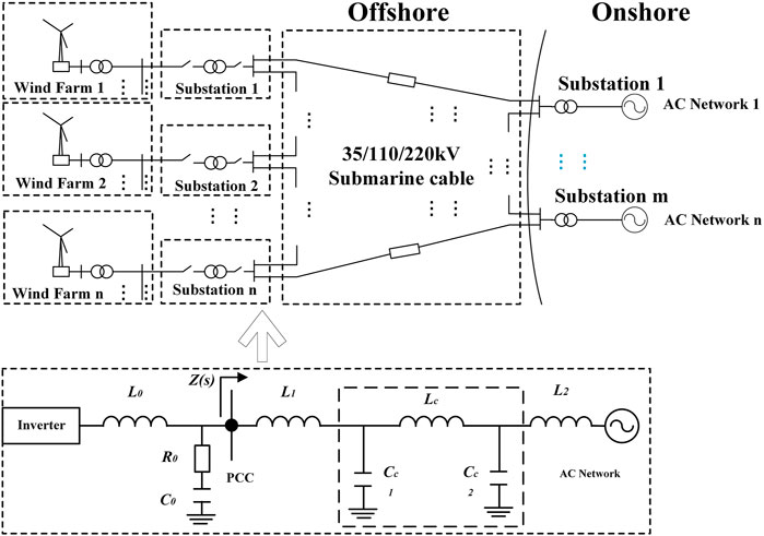
FIGURE 1. Structural diagram and equivalent circuit of offshore wind power transmission system.
The length of HVAC submarine cables for near-sea wind farms is generally within 100km, so π-type equivalent circuit can be used as the equivalent model of HVAC cable line (Wu et al., 2017), Lc is the equivalent inductance of the HVAC cable, Cc1 and Cc2 are the equivalent charging capacitances of the HVAC cable, and both have the same value. L2 is the equivalent inductance of the onshore AC power network, the PCC point is the offshore wind power grid connection point, and Z(s) is the equivalent impedance of the power grid at the port PCC point. Once a transient fault occurs on the cable system, the impedance Z(s) could change correspondingly; therefore, the active protection based on the change of sheath current in the cable becomes possible.
3 Theoretical Analysis of the Cable Fault Process
According to the simplified analysis of practical application, the cross-connection configuration of submarine cable is composed of three small cable segments (L1, L2, and L3) with slightly different lengths. The metal cable sheath of three-phase cable is directly grounded at the junction boxes at both ends of each phase. The function of C1 and C2 junction boxes is to realize the cross interconnection of cable commutation. Figure 2 shows a typical cable cross interconnection scheme. Figure 3 is a simplified form of Figure 2, focusing on the current flowing loop in the cable sheath. There are three induced-current circuits (Jl1, Jl2, and Jl3) in the typical commutation cable sheath, and the load-current passes through three-phase conductors (J1, J2, and J3). The sheath current passes through three different cable sheath circuits, i.e., circuit 1 as the red line Jl1, circuit 2 as the blue line Jl2, and circuit 3 as the green line Jl3. As described in Dong et al. (2017), the total induced current generated in the three cable sheath circuits consists of two parts, namely the leakage current passing through the main insulation and the circulating current caused by unbalanced induced voltage.

FIGURE 2. Circuit diagram of metal sheath of high-voltage cable with cross interconnection.
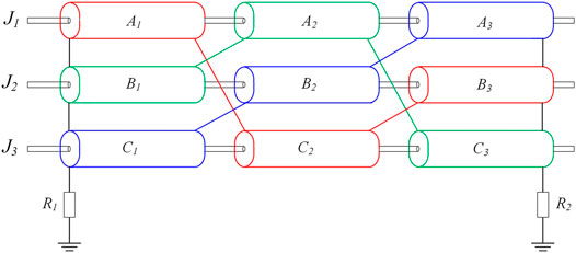
FIGURE 3. Simplified cross connect configuration.
3.1 Cable Sheath Induced Current Caused by Magnetic Coupling
The induced voltage in each cable sheath loop is caused by the load currents passing through the three-phase conductors and the induced current passing through metal sheaths. The load-current passing through the three-phase cables (J1, J2, and J3) could produce induced voltage on three-phase cable lines (L1, L2, and L3) and three-phase cable sheath loop (Jl1, Jl2, and Jl3). The induced voltage caused by load-current can be calculated as follows:
where Uil-Lj is the induced voltage generated by the load-current passing through the cable sheath circuit with length of Lj. Xc-s is the mutual inductance between the cable conductor and its sheath per unit length. Xsi-sj is the mutual inductance between ith sheath and jth sheath per unit length. According to the Guo et al. (2020) and Biswas and Nayak (2021), the aforementioned mutual inductances can be calculated as follows:
where De is the equivalent distance of cable sheath to ground, Si-j is the distance between cable ith sheath and jth sheath, and rs is the radius of the sheath per phase.
As shown in Figure 3, the load-current of three-phase cable conductors (J1, J2, and J3) could generate induced voltage in the three-phase cable sheath circuit (Jl1, Jl2, and Jl3), which can be calculated by the following expression:
Similarly, induced current on the metal cable sheath (Jl1, Jl2, and Jl3) could also cause the induced voltage in each cross-section of cable sheath (L1, L2, and L3), which can be calculated by the following equations:
where Uis-Lj is the induced voltage generated in the ith cable sheath loop by the induced current. Zs is the cable sheath impedance per length unit. Rs is the resistivity of the sheath. The relationship between Zs and Rs can be described as
The induced current of three-phase cable sheath (Jl1, Jl2, and Jl3) could generate induced voltage in the three-phase cable sheath circuit (Jl1, Jl2, and Jl3), which can be calculated by the following expression:
As described previously, the induced voltage of the cable sheath circuit consists of two parts, i.e., the voltage generated by the load-current and the voltage generated by the induced current of the cable sheath. The total induced voltage in each cable sheath loop can be summed as
In addition, since both ends of the cable sheath are grounded, the current of the three sheath circuits flows through the grounding resistors R1 and R2. Therefore, the following constraints need to be met.
3.2 Cable Sheath Induced Current Caused by Capacitive Coupling
The calculation method of induced current caused by capacitive coupling in cable sheath is the same as that in Eq. 6. The current generated by magnetic coupling (Il1m, Il2m, Il3m) remains constant along each circuit, but it is well known that the capacitive current is directly proportional to the length of cable sheath, and there are two cable cross transpositions (C1 and C2) in three sections of cable. Therefore, the capacitive current of each section of cable sheath circuit is composed of two parts, and the capacitive current at C1 cross transposition is defined as Il1c1, Il2c1, and Il3c1, and the capacitive currents at C2 cross transposition are Il1c2, Il2c2, and Il3c2.
Then, the capacitive induced current of each cable sheath loop is the superposition of capacitive current and magnetic coupling current, as described in the following equations (Xia, 2008):
4 Protection Method Based on Active Sheath Current Detection
4.1 Modelling of Submarine Cables
The typical single-core submarine cable has a multi-layer structure, and the typical laying arrangements are shown in Figure 4. The left side is the common arrangement of three-phase single-core cable, which is arranged vertically, and the right side is the section of single-phase single-core cable. Typical single-core submarine cables are composed of the following parts: conductor, XLPE insulation, wrapping layer, and outer sheath, along with an embedded optical fiber as the data communication unit. There are shielding layers between conductor and insulating layer, and insulating layer and wrapping layer; the relative dielectric constant and permeability of different layer materials are different. The material parameters of the single-core cable selected in this study are shown in Table 1 (Guo and Lam, 2018). The structure is relatively simple and involves only three parts: conductor, insulating layer, and sheath. The submarine cable system used in this research is a typical 220-kV three-phase single-core cable, and two types of layout are investigated, i.e., horizontal layout and three-leaf layout.
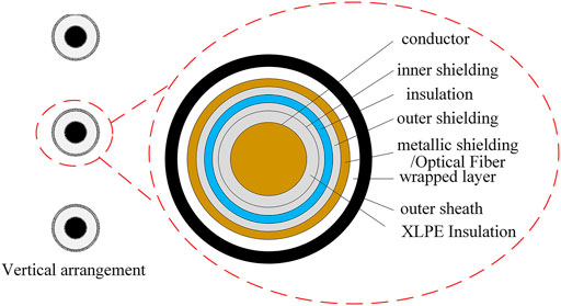
FIGURE 4. Schematic diagram of multi-layer structure of typical single-core cable.
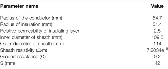
TABLE 1. Material parameters of typical single-core cable
To accurately simulate the different types of defects in cable sheath, it is necessary to carry out refined modeling of cable structure in ATP-EMTP software. In the following study, the single-core cable system is designed in the software with proper parameters defined as in Table 1. The layouts of three-phase single-core cables are set as three-phase cable plane layout and trilobal symmetrical layout (Abu-Elanien et al., 2021; Li et al., 2019). The cross-sections of the two layout schemes are shown in Figure 5.

FIGURE 5. Different arrangements of single-core cable.
4.2 Simulation Setups
This section describes the simulation procedure for calculating sheath current when there are different defects occurring. The induced current in cable sheath during normal operation is used as the reference for comparison. Particularly, the sheath current at two cross interconnections (C1 and C2) of the three sections of cable is studied, along with the consideration of the influence of different cable layouts on the sheath current.
As shown in Figure 2, the three-phase sheath current at two cross interconnections (C1 and C2) is analyzed according to the demand, i.e., I1a, I1b, I1c, I2a, I2b, and I2c, which can be calculated from Eq. 12. It is noted that the sheath current is sampled before cable commutation.
The length of three sections of submarine cable is set as L1 (540 m), L2 (600 m), and L3 (660 m) in the simulation. It is noted that there are no essential differences in the simulation when cable lengths are set to 2 km compared with the actual cable length of approximately 100 km; therefore, the total length in simulation is set to 2 km to simplify the calculation. The cable system simulation model with cross interconnection device is established by EMTP software, as shown in Figure 6. The cable simulation system adopts π-type equivalent circuit model. The resistance value marked “f” is very small, which is only used to connect the three-phase cable to the grounding resistors R1 and R2, both with resistance of 0.2 Ω. The relevant parameter settings of cable and power system are consistent with the theoretical calculation. For the power frequency simulation system, the simulation step is 1 μs and the overall simulation time is 1 s. To verify the feasibility of the established ATP-EMTP simulation model, the analytic calculation of the sheath current based on theoretical equations in (1)–(12) is carried out in MATLAB software.

FIGURE 6. Simulation model of induced current in cable sheath.
It can be seen from Figure 7 that the maximum value of induced current in the metal sheath is about 100 A, with current amplitudes in two phases out of the three phases that are very close, and the current amplitude of the other phase is about half of the maximum. The phase angle of the two-phase current components with the same amplitude is also relatively consistent, whereas the phase angle of other phase current is 1/8 power frequency cycle away from them. At the same time, the existence of the commutation device has a significant effect on both the amplitude and phase angle of the sheath currents.
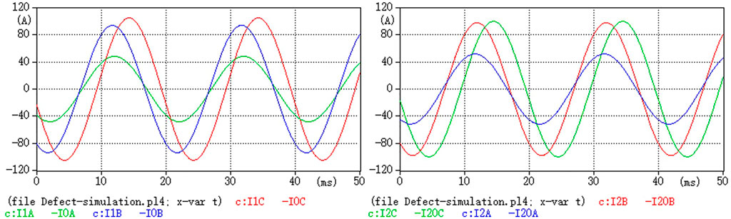
FIGURE 7. Simulation results of the induced current of the cable sheath under normal operation.
The comparisons of calculated induced cable sheath currents under normal operation by the MATLAB and the ATP-EMTP are listed in Table 2. It can be seen from Table 2 that the modeling results of EMTP software are basically the same as the calculation results of the theoretical derivation formula in MATLAB, which confirms the feasibility of using ATP-EMTP modeling method to calculate the changing trends of sheath-induced current under different system defects.

TABLE 2. Simulation and theoretical calculation results of the induced current of the cable sheath
4.3 Protection Boundary Based on Sheath Current Measurements
To get a clear protection boundary for active fault diagnosis, the current measured at the cable cross interconnection under normal operation is normalized in the unit of p.u. and set as the reference. Then the induced current under different cable sheath defects is compared with the reference value, expressed as multiples of the reference. In Khamlichi et al. (2017), a specialized ranking for the induced cable sheath current is proposed, that is, the fault currents expressed as multiples of the reference values are further divided into four discrete levels, namely 0, 1, 2, and 3. The basis of this ranking is to eliminate the up-and-down fluctuation of the normal sheath current value by 25%. Once exceeding this value, a real fault is determined. However, the definition of large fault current in this ranking is not clear enough. Therefore, an improved ranking method is proposed in this paper, with the separation of the judgment range of large fault current defined by 3.5 p.u. boundary. Table 3 presents the details for improved rankings.
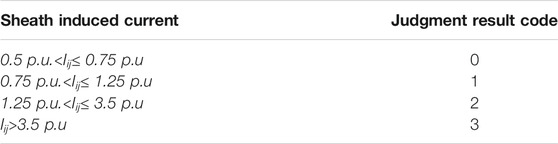
TABLE 3. Judgment standard for induced current of cable sheath
By using the improved ranking method, the electromagnetic defects that occurred in the cable can be represented by a 6-bit general code, and the combination of different codes can reflect the defect type and location of the cable sheath in real time. Considering the normal current fluctuation, the fluctuation amplitude is set as 25%, with the 6-bit code for normal condition displayed as 111111. Once the 6-digit code is different from 111111, certain faults or defects possibly occurred in the wind power transmission system.
5 Simulation Verification and Practical Application
According to the authorized operation data of offshore wind transmission systems, three kinds of defects are analyzed as follows: loss of electrical continuity of cable sheath grounding circuit, water immersion in the junction box, and short circuit between the connector segments.
5.1 Simulation Verification and Analysis
5.1.1 Loss of Electrical Continuity of Cable Sheath Circuit
Electrical continuity refers to the electrical continuity of the grounding line. In ATP software, the defect is simulated by inserting infinite resistance into each circuit of the cable sheath, and the defect location is selected at starting terminal Tb, first intersection C1, second intersection C2, and terminal TE (refer to Figure 2). The current measuring results come from a set of six sensors (i1a, i1b, i1c, i1c, i2A, i2b) and C2 (see Figure 2) located at the intersection of two sheaths.
1) Horizontal Layout of Submarine Cables
In case of electrical continuity loss defect in the sheath grounding circuit, the induced current of the cable sheath under different defect positions shall be obtained, and the current value under the corresponding defect fault shall be compared with the reference value under normal operation. It is indicated that when the electrical continuity is lost at a certain position in the cable sheath grounding circuit, the cable induced current at other positions except this position is relatively close, but the cable sheath induced current drops to very small at the position where the electrical continuity is lost. Comparing the rated induced current value of cable sheath, the generated standardized code indicates the defect type, which is shown in Figure 8.
2) Trefoil Layout of Submarine Cables
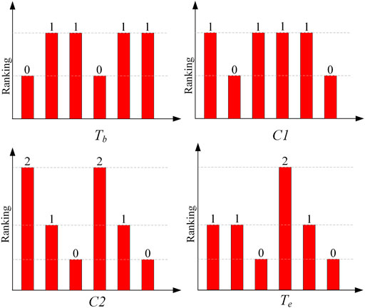
FIGURE 8. Defect code diagram of electrical continuity loss of cable sheath in horizontal layout.
When the sheath grounding circuit has electrical continuity loss defects, it is indicated that when the cable with three-leaf layout encounters sheath electrical continuity loss defects, the situation is similar to that of the cable with horizontal layout. Except for the locations where defects occur, the induced current values of the cables at other locations are relatively close. Comparing the rated induced current value of cable sheath, the generated standardized code indicates the defect type, as shown in Figure 9.
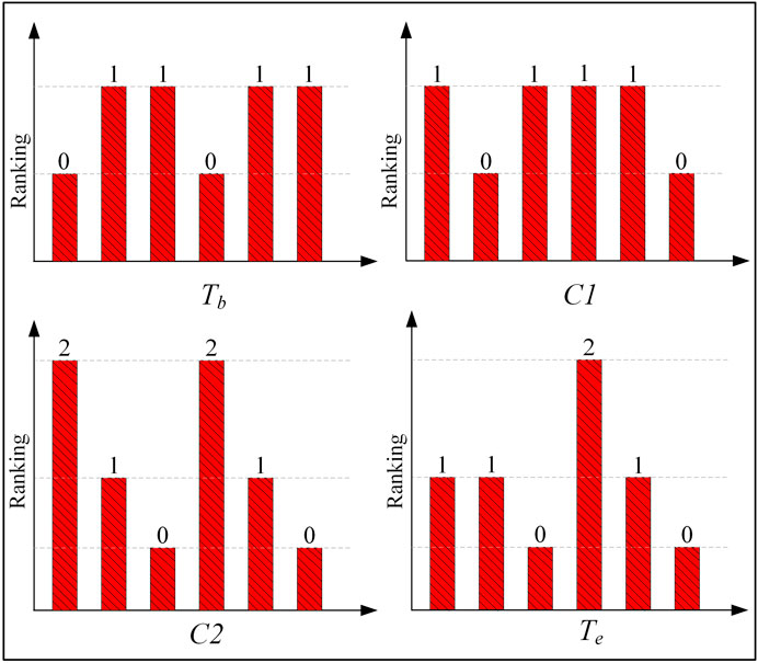
FIGURE 9. Code diagram of electrical continuity loss defect code diagram of three-leaf layout cable sheath.
It can be seen from Figure 9 that when the electrical continuity loss also contains the disconnection in sheath junction box internal due to breakage or broken wires. In the simulation setup, broken wire was selected to simulate this situation, the simulation results are consistent with the other stimulation using insertion of large resistors, this is because in EMTP software, when resistance greater than 1E8 is embedded into the circuit, the software automatically recognize the circuit as in a disconnected state.
5.1.2 Water Immersion of Junction Box
Water immersion in the junction box connecting the sheath could cause the three cable sheaths to be immersed and short circuit at the same time. This defect is realized in the ATP through a three-phase short circuit at the corresponding sheathed junction box. It is indicated that when the junction box has a water immersion defect, it has a greater impact on the induced current in the cable sheath, and some locations could have a fault current far greater than the rated current. The specific current value is compared with the rated induced current value of the cable sheath, with the normalized code indicating the defect type, as shown in Figure 10.
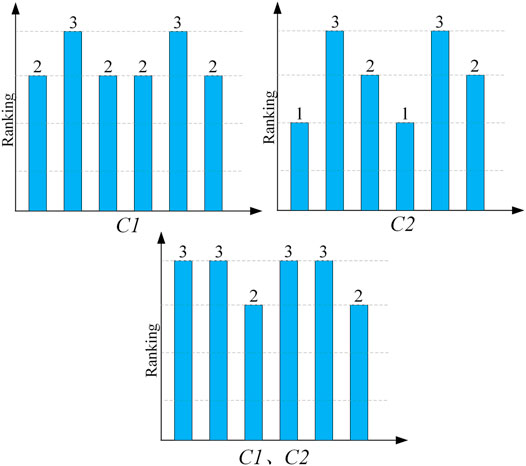
FIGURE 10. Code diagram of water immersion defect in the horizontal layout of the cable sheath junction box.
It can be seen from Figure 10 that multiple consecutive values of three appear in the defect code, and there is no value of 0, indicating that the fault is that the junction box is immersed in water, and C1 and C2 are both immersed in water.
5.1.3 Short-Circuit Between Section Sheaths
The probability of short circuit between normally arranged cable sheaths is small, but when cross interconnected commutation device is configured, short-circuit fault occurs easily between cable sheaths in the interconnection junction box. In ATP-EMTP software, a very small resistance can be connected on both sides of the interconnection junction box to realize this defect. Taking the short circuit of cable sheath at junction box C1 as an example, the typical differential current indicates that when the short circuit between the metal sheaths at the cable cross interconnection box has a great impact on the induced current in the cable sheath, a fault current far greater than the rated current would appear in some locations, and at the same time, a fault current far less than the rated current appears. The value of the fault current and the specific current value are compared with the rated induced current value of the cable sheaths, and the standardized code generated indicates the defect type, as shown in Figure 11.
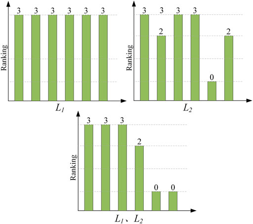
FIGURE 11. Code diagram of short-circuit defect code of horizontal cable sheath section.
It can be seen from Figure 11 that there are multiple consecutive values of three in the defect code, and the accompanying value of 0 indicates that the fault is a cross-sectional short-circuit defect, and then the specific indication code is compared to further determine the location of the defect.
5.2 Hardware Implementation of the Proposed Active Protection Scheme
The practical implantation of the active protection scheme can be carried out as shown in Figure 12. The hardware for sheath current measurement and processing consists of four parts, i.e., data collection units embedded on the cable with sampling rate of 2 MHz and powered by ultracapacitors. These data collection units can be directly retrofitted from the broadband current monitoring systems mounted on the overhead line transmission system (Si et al., 2016). Then the collected sheath current data can be transferred through the optical fiber embedded in the submarine cable and gathered at the onshore control room. After data normalization, the sheath current data would be processed by the proposed active protection algorithm on PC. Eventually, the precise fault location, risk level, and fault types of the electromagnetic transients can be classified.
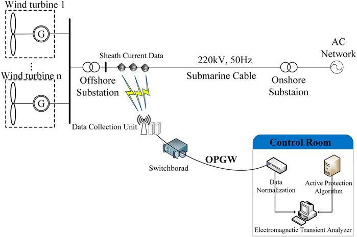
FIGURE 12. Hardware topology of sheath current-based active protection system.
Particularly, the working principles for current collection units, which are used to carry out online monitoring of the sheath current, are described. This unit could realize the full wave recording of low frequency at ∼kHz and triggering wave recording of high frequency at ∼MHz. The full wave recording records all waveform at ∼kHz acquisition speed, and triggering wave recording triggers waveform recording of ∼MHz according to the frequency or current amplitude disturbance of signal collected at ∼kHz. The integrator is used to integrate the signal of Roche coil to obtain the line power frequency current and transient current waveform. The data acquisition module is used to collect, calculate, and analyze the collected power frequency current signal, and collect and store the transient current waveform signal. The module could use A/D converter chip for high and low frequency, with sampling rate in the order of Ksps for low frequency and Msps for high frequency. To record data on time, triggering should be carried out to record the waveform data of few seconds before and after the occurrence of trigger. The time could be initially set as 1.2 s before and 1.2 s after the occurrence of trigger. The power module could supply power to the online data collection unit through wire induction and supercapacitor. The sampling data of the current data acquisition unit are uploaded to the main station of the system through the fiber channel. The size of each measurement unit is less than 2 kg and the diameter is less than 200 mm. Compared with the general sea cable, the cost is almost the same and will not have a significant impact on cable transformation and laying.
6 Conclusion
An active protection scheme for offshore wind power transmission systems connected with HVAC submarine cables is proposed in this paper. Simulation results illustrated that the method can accurately locate the fault areas of electromagnetic transients when the cable sheath current is measured and normalized appropriately, and this protective scheme is effective for achieving a combination of control and protection through the data communication of optical fibers in the submarine cables. Compared with the conventional on-line monitoring protection methods, this technique only needs to add few signal injection modules with high sampling frequency into the submarine optical fibers. The proposed method is also unaffected by measuring noise and cable distributed capacitance. The new protection scheme is therefore feasible for industry application in large and complex offshore wind farms.
Data Availability Statement
The datasets presented in this article are not readily available because the data are for scientific research only. Requests to access the datasets should be directed to YS (c3lxY2FibGVAMTYzLmNvbQ==).
Author Contributions
The individual contributions of the authors are as follows: data curation, YZ; formal analysis, QL; methodology, RX; supervision, YS; writing (original draft), YZ. All authors have read and agreed to the published version of the article.
Funding
This study received funding from Research and Application of Key Technologies for Sensory Fusion and Edge Empowerment of High Voltage Cable Lines in Urban Power Grids (Science and Technology Project No 52020121001C of State Grid Co. Ltd.). The funder was not involved in the study design, collection, analysis, interpretation of data, the writing of this article, or the decision to submit it for publication.
Conflict of Interest
Authors YZ and YS were employed by State Grid Beijing Powercable Company.
The remaining authors declare that the research was conducted in the absence of any commercial or financial relationships that could be construed as a potential conflict of interest.
Publisher’s Note
All claims expressed in this article are solely those of the authors and do not necessarily represent those of their affiliated organizations, or those of the publisher, the editors, and the reviewers. Any product that may be evaluated in this article, or claim that may be made by its manufacturer, is not guaranteed or endorsed by the publisher.
References
Abeynayake, G., Van Acker, T., Hertem, D. V., and Liang, J. (2021). Analytical Model for Availability Assessment of Large-Scale Offshore Wind Farms Including Their Collector System. IEEE Trans. Sustain. Energ. 12, 1974–1983. doi:10.1109/TSTE.2021.3075182
Abu-Elanien, A. E. B., Abdel-Khalik, A. S., and Massoud, A. M. (2021). Multi-Terminal HVDC System with Offshore Wind Farms under Anomalous Conditions: Stability Assessment. IEEE Access 9, 92661–92675. doi:10.1109/ACCESS.2021.3092696
Biswas, S., and Nayak, P. K. (2021). A Fault Detection and Classification Scheme for Unified Power Flow Controller Compensated Transmission Lines Connecting Wind Farms. IEEE Syst. J. 15 (1), 297–306. doi:10.1109/JSYST.2020.2964421
Chatzipetros, D., and Pilgrim, J. A. (2020). Impact of Proximity Effects on Sheath Losses in Trefoil Cable Arrangements. IEEE Trans. Power Deliv. 35 (2), 455–463. doi:10.1109/TPWRD.2019.2896490
dong, X., yang, Y., Zhou, C., and Hepburn, D. M. (2017). Online Monitoring and Diagnosis of HV Cable Faults by Sheath System Currents. IEEE Trans. Power Deliv. 32 (5), 2281–2290. doi:10.1109/TPWRD.2017.2665818
Guo, G., Zha, K., Zhang, J., Wang, Z., Zhang, F., and Cao, J. (2020). Grounding Fault in Series-Connection-Based Offshore Wind Farms: Fault Clearance. IEEE Trans. Power Electron. 35 (9), 9357–9367. doi:10.1109/TPEL.2020.2971640
Guo, H., and Lam, S. (2018). Fault Analysis and Protection of a Series-DC Collection and Transmission System. IEEE Trans. Ind. Applicat. 54 (5), 5417–5428. doi:10.1109/TIA.2018.2843789
Huang, S., Wu, Q., Liao, W., Wu, G., Li, X., and Wei, J. (2021). Adaptive Droop-Based Hierarchical Optimal Voltage Control Scheme for VSC-HVDC Connected Offshore Wind Farm. IEEE Trans. Ind. Inf. 17, 8165–8176. doi:10.1109/TII.2021.3065375
Khamlichi, A., Adel, M., Garnacho, F., and Rovira, J. (2017). Measuring cable Sheath Currents to Detect Defects in cable Sheath Connections. 52nd Int. Universities Power Eng. Conf. (Upec), 1–6. doi:10.1109/UPEC.2017.8231978
Lakshmanan, P., Sun, R., and Liang, J. (2021). Electrical Collection Systems for Offshore Wind Farms - a Review. Csee Jpes 7 (5), 1078–1092. doi:10.17775/CSEEJPES.2020.05050
Li, G., Liang, J., Ma, F., Ugalde-Loo, C. E., and Liang, H. (2019). Analysis of Single-Phase-To-Ground Faults at the Valve-Side of HB-MMCs in HVDC Systems. IEEE Trans. Ind. Electron. 66 (3), 2444–2453. doi:10.1109/TIE.2018.2829666
Li, R., Yu, L., and Xu, L. (2019). Offshore AC Fault Protection of Diode Rectifier Unit-Based HVdc System for Wind Energy Transmission. IEEE Trans. Ind. Electron. 66 (7), 5289–5299. doi:10.1109/TIE.2018.2869357
Shi, L., Adam, G. P., Li, R., and Xu, L. (2020). Control of Offshore MMC during Asymmetric Offshore AC Faults for Wind Power Transmission. IEEE J. Emerg. Sel. Top. Power Electron. 8 (2), 1074–1083. doi:10.1109/JESTPE.2019.2930399
Si, W. R., ChenZhao, Z. F. D. D., and Zhao, W. B. (2016). Review on Sensors and Measurement Technologies Used for Transient Over-voltage of Power Grid. High Voltage Eng. 42 (04), 1124–1141. doi:10.13336/j.1003-6520.hve.20160405022
Teng, W., Wang, X., Wang, X., Meng, Y., and Shi, W. (2019). An Improved Support Vector Clustering Approach to Dynamic Aggregation of Large Wind Farms. Csee Jpes 5, 2. doi:10.17775/CSEEJPES.2016.01600
Wang, P., Zhang, Z., Huang, Q., Wang, N., Zhang, X., and Lee, W.-J. (2018). Improved Wind Farm Aggregated Modeling Method for Large-Scale Power System Stability Studies. IEEE Trans. Power Syst. 33, 6332–6342. doi:10.1109/TPWRS.2018.2828411
Wu, Y.-K., Su, P.-E., Su, Y.-S., Wu, T.-Y., and Tan, W.-S. (2017). Economics- and Reliability-Based Design for an Offshore Wind Farm. IEEE Trans. Ind. Applicat. 53 (6), 5139–5149. doi:10.1109/TIA.2017.2737399
Keywords: offshore wind farm, XLPE submarine cable, submarine cable, sheath fault current, electromagnetic transients, active protection
Citation: Zhao Y, Liu Q, Xia R and Shang Y (2022) Active Cable Sheath Current-Based Protection Scheme for an Offshore HVAC Wind Transmission System. Front. Energy Res. 10:844474. doi: 10.3389/fenrg.2022.844474
Received: 28 December 2021; Accepted: 31 January 2022;
Published: 09 March 2022.
Edited by:
Jian Zhao, Shanghai University of Electric Power, ChinaReviewed by:
Zepeng Lv, Xi’an Jiaotong University, ChinaMeng Huang, North China Electric Power University, China
Yunhe Wang, Chongqing University, China
Copyright © 2022 Zhao, Liu, Xia and Shang. This is an open-access article distributed under the terms of the Creative Commons Attribution License (CC BY). The use, distribution or reproduction in other forums is permitted, provided the original author(s) and the copyright owner(s) are credited and that the original publication in this journal is cited, in accordance with accepted academic practice. No use, distribution or reproduction is permitted which does not comply with these terms.
*Correspondence: Yingqiang Shang, c3lxY2FibGVAMTYzLmNvbQ==