 Yingjun Wu
 Zhanyu Shi
- College of Energy and Electrical Engineering, Hohai University, Nanjing, China
The integrated energy system (IES) plays a key role in energy conservation and emission reduction. In order to realize the low-carbon economic dispatch of the IES, current studies usually utilize the fixed and the ladder-type pricing mechanism-based carbon emission unit cost (CEUC) in the optimal dispatch model. However, those mechanisms fail to take carbon emissions levels of the system into account, and the relevant parameters, such as the interval length, are hard to set. In order to tackle this challenge, a CEUC model with a dynamic reward and penalty pricing mechanism (DRPPM) is constructed. And then an optimal dispatch model to minimize the comprehensive operation cost, including the carbon emission cost, the energy purchasing cost, and the equipment operation cost, is proposed. At last, an actual electricity–heat–cooling–gas IES is employed to analyze the impact of parameters of the CEUC model on the dispatch.
Introduction
The increasing energy demand leads to the massive utilization of fossil fuels. The trend poses huge pressure on the environment such as global warming (Wu et al., 2021). Therefore, energy conservation and emission reduction have become an inevitable choice in the development of energy systems (Li H et al., 2021; Yang et al., 2021). The IES provides a new direction for global energy reform (Meibom et al., 2013; Mancarella, 2014) because it can improve the energy efficiency and the consumption of clean energy and ensure the security and stability of the energy system by coordinating and optimizing multi-energy (Ceseña and Mancarella, 2019).
At present, many valuable research studies on the optimal dispatch of the IES had been done from various perspectives. And the results of these research studies provide some ideas and methods for researchers to refer to. However, the existing research studies have some problems: 1) Most research studies only consider the economics of the IES but ignore the environmental issues. 2) The CEUC model in these research studies cannot be applied completely in practical IES.
Current studies on the IES mainly focus on the formation of the optimal dispatch model (Wang et al., 2019; Chen et al., 2020; Lu et al., 2020). The objective of the model is to minimize the operating cost or maximize the profit of the IES, and to study the output of various types of equipment in the system. Lu et al. (2020) established a bi-level economic dispatch model to analyze the optimal dispatch of the IES considering wind turbine (WT) and P2G (Tang and Bao, 2020); analyzed the uncertainties of wind power, electricity load (EL), and gas load (GL) based on the scenario analysis method, and then established a dispatch model of the electricity–gas IES. Li J et al. (2021) proposed an economic dispatch model for the electricity–heat IES considering the reserve benefits of thermal energy storage equipment and the heuristic day-ahead coordinated dispatch strategy.
With the pressure of the environment concerning, the carbon emission cost must be considered in the dispatch of the IES (Zhang et al., 2017; Li et al., 2019.; Ren et al., 2019). The mainstream calculation methods of carbon emission cost mainly include two types: one is based on the fixed CEUC model (Zhang R et al., 2018) and the other is based on the ladder-type CEUC model (Zhang et al., 2019). The first calculation method adopts certain penalties for systems whose carbon emissions are higher than their carbon emission quotas (Xiang et al., 2021; Yang et al., 2021). The second calculation method provides economic compensation when the system’s carbon emissions are less than its carbon emission quota. Additionally, the smaller the interval corresponding to the surplus carbon emission quota, the higher will be the unit compensation price. On the contrary, when the system’s carbon emissions are higher than its carbon emission quota, a certain economic penalty is imposed, and the larger the interval corresponding to the excess carbon emissions, the higher will be the corresponding unit penalty cost (Zhang et al., 2020; Cui Y et al., 2021).
However, there still exist several problems in those methods. The first calculation method adopts fixed CEUC to calculate the carbon emission cost of the IES, which leads to low incentive for high carbon-emitting systems to reduce carbon emissions. It is also not conducive to the healthy development of the IES. Compared with the first calculation method, the second can better mobilize various systems to participate in energy conservation and emission reduction. Yet, the ladder-type calculation method is involved in two disgusting problems such as unreasonable selection of the size and number of intervals and difficulty in implementation. In addition, current references usually ignore the carbon dioxide absorbed by the power-to-gas device (P2G), and the carbon emissions from the production of purchased electricity and the consumption of the GL in the carbon emission cost calculation.
Because of the shortcomings of the aforementioned CEUC model, a CEUC model with a DRPPM is proposed. A low-carbon economic dispatch model of the IES to minimize the comprehensive operation cost, including the carbon emission cost, the energy purchasing cost, and the equipment operation cost is constructed. This model can better coordinate all equipment in the IES participating in the energy conservation and emission reduction, improving the rationality of carbon emission cost calculation and effectively reducing the carbon emissions of the IES. This article has two major contributions:
(1) A CEUC model based on the DRPPM is proposed. It allows for decision-makers to rationally set the relevant parameters and consider the characteristics of the IES.
(2) Based on the aforementioned mechanism, an optimal dispatch model is constructed for the IES to ensure its economics and eco-friendly performance, especially reducing the carbon emissions of the equipment.
The remainder of this article is organized as follows: Section 2 constructs a general dispatch model for the IES under the background of the low-carbon economy. Meanwhile, according to the deficiencies of the fixed CEUC model and the ladder-type CEUC model, a CEUC model based on a DRPPM is proposed. A low-carbon economic dispatch model considering the unit cost of carbon emissions based on the proposed mechanism is established in Section 3. Section 4 demonstrates the optimization dispatch results of case studies. Finally, some conclusions are drawn in Section 5.
CEUC Model
Dispatch Model of the IES
The IES operator should consider not only the economics of system operation but also the carbon emissions generated by the IES. The objective of the optimal dispatch of the IES is to minimize the comprehensive operation cost by adjusting the output of thermal power units (TP), combined cooling, heating, power units (CCHP), and other equipment on the production side of the IES, the thermal energy produced by electric heating boilers (EH), the cooling energy produced by electrical chillers (EC), and the hydrogen production capacity of P2G, and the charging and discharging power of the energy storage device (ESD) on the network side. The comprehensive cost consists of the equipment operation cost, the energy purchasing cost, and the carbon emission cost of the IES. The dispatch model can be represented as follows:
where
The carbon emission cost CT(x) is related to the quantities of carbon emissions and their unit cost. Generally, the total carbon emission cost can be calculated by the methods based on the fixed unit cost or the ladder-type cost.
The fixed CEUC model is represented as follows:
The ladder-type CEUC model is represented as follows:
where c is the baseline value of the CEUC; E and E*,respectively, represent the actual carbon emissions and carbon emission quota of the system at time t; i is the number of the ladder in the ladder-type function;
However, the fixed CEUC model does not distinguish the systems with different carbon emissions levels. In addition, the length of fixed carbon emission intervals and the number of intervals under the ladder-type CEUC model are difficult to determine.
CEUC Model Based on the DRPPM
To address the problems proposed in the previous section, a CEUC model based on the DRPPM is introduced, which can be expressed as follows:
where a and b, respectively, represent the quadratic and primary term coefficients of the CEUC model and c is the baseline value of the CEUC model.
As it can be seen from the model, the proposed model uses a dynamically changing CEUC to avoid the problem that the fixed CEUC cannot limit the overall carbon emissions well. Also the higher the carbon emission of the IES, the higher will be the corresponding CEUC under this model. For the problems of interval length and number of ladders setting in the ladder-type CEUC model, the proposed model replaces the discontinuous ladder-type CEUC model with a continuous CEUC model based on the DRPPM.
Low-Carbon Economic Dispatch Model Considering CEUC Based on the DRPPM
Objective Function
Equipment Operation Cost
The operation cost of TP, WT (Yang et al., 2017), photovoltaic power (PV) (Liu et al., 2020), CCHP, gas boiler (GB), EH, P2G, EC, absorption refrigerator (AR), electricity storage (ES), thermal storage (TS), cooling storage (CS), and gas storage (GS) at time t are shown in (7)–(19):
where
The equipment operation cost of the IES at time t can be expressed as follows:
where Ω represents various equipment in the IES, including TP, WT, PV, CCHP, and GB on the production side, EH, P2G, EC, AR, and ESD on the network side;
Energy Purchasing Cost
In order to maintain the balance of energy supply and load demand, the IES operator needs to purchase electricity and natural gas from the PG and NGN. Thus, the energy purchasing cost of the IES includes the electricity purchasing cost and the gas purchasing cost. The energy purchasing cost of the IES at time t can be written as follows:
where
Carbon Emission Cost
The calculation of the carbon emission cost can be divided into three steps: 1) determining the carbon emission quota; 2) calculating the actual carbon emissions; 3) calculating the carbon emission cost.
On the production side of the IES, there are GB, CCHP, and other energy production equipment that convert primary energy into secondary energy, and the purchased electricity of the IES which is generated from TP. For the aforementioned equipment, the carbon emission quota and the actual carbon emissions corresponding to its output need to be determined. In addition, the carbon emission quota of PV and WT also needs to be calculated.
The network side of the IES mainly involves the conversion process of various secondary energy sources. Carbon emissions are rarely generated during this process, and only the carbon emissions absorbed by P2G need to be determined.
Since the GL on the load side is mainly used as fuel for combustion, it is also necessary to calculate the carbon emission quota and actual carbon emissions of the GL.
1) Carbon Emission Quota
The calculation method for the carbon emission quota is based on the output of each piece of equipment. The initial carbon emission quota is proportional to the output of each piece of equipment. Taking TP and CCHP for example, The carbon emission quota of TP is determined by its power generation, the more the output of TP, the more the carbon emission quota it gains; The carbon emission allowance of CCHP depends on its output of electrical, thermal, and cooling energy, different types of energy corresponding to different carbon emission quota factors. The more the output of CCHP, the more will be the carbon emission quota it gains.
The carbon emission quota of the IES is composed of the carbon emission quota of the production side, the carbon emission quota of the network side, and the carbon emission quota of the load side.
The carbon emission quota of the production side at time t can be calculated as follows:
where
The carbon emission quota of the load side at time t can be expressed as follows:
where
Thus, the carbon emission quota of the IES at time t can be calculated as follows:
2) Actual Carbon Emissions
The actual carbon emissions of the IES are composed of the carbon emissions of the production side, the carbon emissions of the network side, and the carbon emissions of the load side. The actual carbon emissions of the production side at time t can be shown as follows:
where
The actual carbon emissions of the network side at time t can be expressed as follows:
where
where
The actual carbon emissions of the IES at time t can be calculated as follows:
3) Carbon Emission Cost
According to the CEUC model based on the DRPPM proposed in Section 2, the carbon emission cost model of the IES can be constructed as follows:
When
Constraints
Equipment Operational Constraints
The operational constraints of TP, WT, PV, CCHP, GB, EH, P2G, EC, AR, and ESD are given in (32)-(40):
1) Operation Constraints of TP
The rated power constraint and ramping constraint of TP are given as follows:
where
2) Operation Constraints of WT and PV
The rated power constraint of WT and PV are constructed as follows:
where
3) Operation Constraints of CCHP
where
4) Operation Constraints of GB
The rated power constraint, ramping constraint, and power balance constraint of GB can be expressed as follows:
where
5) Operation Constraints of EH
The rated power constraint, ramping constraint, and power balance constraint of EH can be shown as follows:
where
6) Operation Constraints of EC
The rated power constraint and power balance constraint of EC can be expressed as follows:
where
7) Operation Constraints of P2G
The rated power constraint and power balance constraint of P2G can be constructed as follows:
where
8) Operation Constraints of AR
The rated power constraint and power balance constraint of AR can be expressed as follows:
where
9) Operation Constraints of ESD
The operation constraints of ESD include power balance constraint, capacity constraint, charge constraint, and discharge constraint. The operation constraints of ESD can be expressed as follows:
where
Power Balance Constraints
In the IES, the EL, heat load (HL), cooling load (CL), and GL at time t meet the following power balance constraints:
where
Case Studies
The Studied IES Introduction
Based on the electricity–heat–cooling–gas IES established in Li H et al. (2021); Li et al. (2018), the effectiveness and practicability of the low-carbon economy dispatch model proposed in this article are verified. The grid structure of the IES is shown in Figure 1. The dispatch period is 24 h. During the dispatch period, the output of the WT and the PV, the load demand of various loads, and the time-of-use price of electricity and gas are shown in Figure 2. The specific parameter of the equipment can be found in He et al. (2018); Wu et al. (2021); Xiang et al. (2021). The carbon emission quota coefficient of TP is 0.798t/MWh. The carbon emission quota coefficient of WT and PV is 0.078t/MWh. The carbon emission quota coefficient of thermal energy and GL is 0.3672t/MWh and 0.18t/MWh (Zhang R et al., 2018; Zhang et al., 2019). And the carbon emission coefficient of each piece of equipment can be found in Cheng et al. (2017); He et al. (2018); Xiang et al. (2021).

FIGURE 1. Grid structure of the electricity-heat-cooling-gas IES.
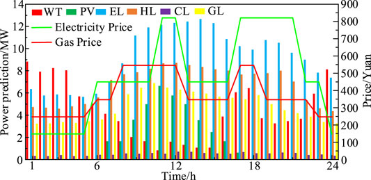
FIGURE 2. Output of PV and WT, cure of load demand, and price of electricity and natural gas.
Results and Analysis
In this section, a TP and the aforementioned IES are, respectively, applied to demonstrate the effectiveness of the proposed low-carbon economic dispatch model. The case studies are set as follows:
Case 1 Low-carbon economic dispatch model considering fixed CEUC. In this case, the baseline value c of the CEUC is 280 yuan/MWh.
Case 2 Low-carbon economic dispatch model considering ladder-type CEUC. In this case, the baseline value c of the CEUC is 280 yuan/MWh, the number of ladders i is 4, and the growth factor
Case 3 Low-carbon economic dispatch model considering CEUC based on the DRPPM. In this case, the baseline value c of the CEUC is 280 yuan/MWh. The quadratic term coefficient a is 5, and the primary term coefficient b is 40.
Analysis of the Relationship Between Unit Power Comprehensive Cost and Output of TP
In this section, the relationship between unit power comprehensive cost and output of TP under different CEUC models is, respectively, analyzed. The rated power of TP is 100 MW, and the carbon emissions of TP show a step change when the output is 76 MW. The analysis results are shown in Figure 3.
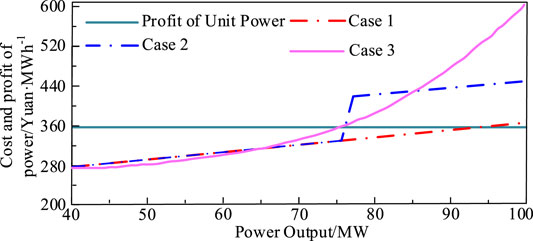
FIGURE 3. Relationship between unit power comprehensive cost and output of TP.
As it can be seen from Figure 3, in case 1, the operator will try to increase the output of TP to 93 MW to get the maximum benefit, but TP also generates huge carbon emissions. In case 2, the unit power comprehensive cost of TP has a segmentation point at 76 MW. When the output of TP is less than 76MW, the comprehensive cost of TP is less than its profit. To make the maximum benefit, the operator will try to increase the output of TP to 76 MW. In addition, to limit the carbon emissions of TP, the operator will try their best to limit the output of TP to less than 76MW, so the carbon emissions in case 2 is less than that in case 1.
In case 3, when the output of TP is less than 75MW, the comprehensive cost of TP is less than its profit. In addition, when the output of TP is higher than 85MW, the comprehensive cost of TP in case 3 is higher than that in case 2. It means that when the load demand is high and the output of TP has to be higher than 75MW, the operator is required to limit the output lower than 85 MW to reduce the carbon emissions in case 3. For example, the operator can replace the output of TP with that of some other low-carbon emission equipment, such as CCHP. It is beneficial for reducing the comprehensive cost. Therefore, under certain conditions, the dispatch model in case 3 has a better ability to limit carbon emissions than that in case 1 and case 2.
Low-Carbon Economic Dispatch Results of the IES
The low-carbon economic dispatch results of the aforementioned IES under three cases can be seen in Figure 4:

FIGURE 4. Low-carbon economic dispatch results.
Compared with case 1, the carbon emission of case 2 was reduced by 29.5t (8.15%). Compared to the carbon emissions of case 1 and case 2, the carbon emission of case 3 is reduced by 52.6t and 23.1t, respectively. In terms of the comprehensive operation cost of the IES, the comprehensive operation cost in case 3 is the highest (295803 Yuan). It is higher than the cost of case 1 and case 2 by 3.79% and 1.32%, respectively. In terms of electricity purchasing cost and gas purchasing cost, case 1 has the highest electricity purchasing cost and the lowest gas purchasing cost. Case 3 has the lowest electricity purchasing cost and the highest gas purchasing cost. The electricity purchasing cost and gas purchasing cost in case 2 are between those in case 1 and case 3. In addition, the carbon emissions in case 1 is the highest, which means that when the constraints of carbon emissions are strengthened, the IES will purchase more natural gas to replace the purchasing of electricity to reduce the penalties when the carbon emissions are too high. Although the energy purchasing cost of the IES will increase in this way, the carbon emissions and the carbon emission cost will be reduced accordingly. Compared with the dispatch model in case 1 and case 2, the dispatch model proposed in this article has a great significance to limit the carbon emissions of the IES, which makes the IES more economically and environment-friendly.
Figures 5–7, respectively, show the operation of electrical load equipment in different cases. Before 6:00, the purchased electricity of the IES in three cases is similar, as well as the output of TP and CCHP. During this period, the system has less demand for EL, but the output of WT and CCHP is high. It results in the overall output of the IES higher than EL. Therefore, the excess electricity is consumed by P2G, which leads to the P2G working at its rated operation state. From 6:00 to 8:00, the purchased electricity of the IES decreases in all three cases, and the P2G still working at rated operation state in case 1, while in case 2 and case 3, the electricity consumption of P2G is significantly reduced, and it decreases more in case 3 than in case 2. Because the CEUC model applied in case 3, the cost of producing natural gas by P2G is higher than the cost of gas purchasing from NGN, thus limiting the output of coal-fired units and power-to-gas equipment. From 9:00 until 15:00, the purchased electricity of the IES and the electricity consumption of P2G are reduced in three cases. Because of the high electricity price during this period, the electricity purchasing cost was also high. The electricity generation equipment only supplies a small amount of its electricity to the P2G. From 16:00 to 21:00, the purchased electricity of the IES and the electricity consumption of P2G are reduced in case 3 due to the high carbon emission cost. The purchased electricity of the IES and the electricity consumption of P2G are increased under the three cases between 22:00 and 24:00. Because of the low electricity price during this period, the operator promotes the output of the P2G by increasing the purchased electricity of IES to meet the system’s demand for natural gas. The comprehensive cost of the IES is relatively lower in this way. And the output of TP in case 1 decreases with the reduction of EL, and the P2G works at the rated operation state. The output of TP in case 3 remains the same, which is different from that in case 1 and case 2.
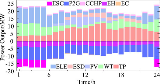
FIGURE 5. Operation of each unit in case 1.
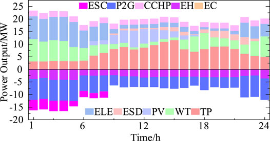
FIGURE 6. Operation of each unit in case 2.
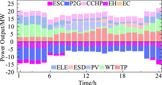
FIGURE 7. Operation of each unit in case 3.
According to the aforementioned analysis, when the carbon emission cost enhances the restriction for the system, the IES operator will reduces the electricity, which generated by the high-carbon emissions unit and increase the purchase of natural gas, which has relatively low-carbon emissions, in order to limit the carbon emissions and compensate for the reduced output of high-carbon emissions unit by increasing the output of the gas-fired units. So, the proposed method is better in reducing carbon emissions and improving the economy of the IES than the other two methods.
The Impact of CEUC on Low-Carbon Economic Dispatch of the IES
The impacts of the baseline value c and the primary term coefficient a of the cost function of carbon emissions in case 3 on the low-carbon economic dispatch of the IES is analyzed in this section.
(1) The impact of the baseline value c of the CEUC on low-carbon economic dispatch of the IES
Figure 8 shows the carbon emission cost and carbon emissions of the IES considering the CEUC based on the DRPPM under different baseline values c of the CEUC model. As the baseline value increases, the carbon emission curve shows a trend of constant, then decreasing, and finally stable as the baseline value of CEUC increases. Also the carbon emission cost curve shows a trend of increasing, then decreasing, and finally stable. When the baseline value c is low, the system carbon emission cost of the IES increases with the increase in the baseline value, while the carbon emissions of the system change little. Because at this stage, the system mainly meets the power load demand through the generation of TP which has lower operating costs compared to CCHP. And the variation of baseline value c has little effect on the carbon emissions of the IES. When the baseline value c is higher than 200 Yuan/t, the carbon emissions of the IES will decrease as the baseline value c increases. Because in order to ensure the economy of the IES, the system reduces the carbon emissions of the system by increasing the output of CCHP to replace the output of TP, which reduces the carbon emission cost of the system to ensure its economy. The carbon emissions of the IES gradually stabilize when the baseline value c is higher than 500 Yuan/t. The output of CCHP does not vary much because of the operational constraints in this situation. However, the installed capacity of CCHP in the IES is smaller than that of TP, which makes the system’s carbon emissions always higher than its carbon emission quota. Therefore, the carbon emission cost increases slightly with the increase in the baseline value.
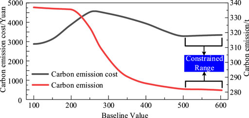
FIGURE 8. Impact of the baseline value c of the CEUC on carbon emissions and carbon emission cost.
Figure 9 shows the electricity purchasing cost and gas purchasing cost of the IES considering the CEUC based on the DRPPM under different baseline values c of the CEUC model. The electricity purchasing cost of the IES shows a trend of constant, then decreasing, and finally stabilizing with the increase in the baseline value. And the gas purchasing cost of the system shows a trend of constant, then increasing and finally stabilizing with the increase in the baseline value. When the baseline value c is low, it has less impact on the operation mode of the system, and the electricity purchasing cost and gas purchasing cost are relatively stable. When the baseline value c is higher than 200 Yuan/t, the electricity purchasing cost of the IES keeps decreasing. While the gas purchasing cost keeps increasing and exceeds the former. Because as the baseline value increases, the system needs to increase the output of the low-carbon emission equipment (CCHP) by increasing the amount of purchased natural gas. The increased output of CCHP can replace a portion of the high carbon-emitting purchased electricity and the output of the thermal units. When the baseline value is higher than 500 Yuan/t, the electricity purchasing cost and gas purchasing cost tend to stabilize due to the operational constraints of CCHP.
(2) The impact of the primary term coefficient b of the CEUC on low-carbon economic dispatch of the IES
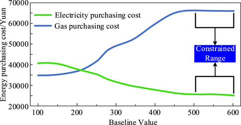
FIGURE 9. Impact of the baseline value c of the CEUC on electricity purchasing and gas purchasing cost.
Figure 10 shows the results when primary term coefficients b varies. With the fixed baseline value c, the output of CCHP and the primary term factor b are positively correlated. Yet, the output of TP decreases as the primary term factor b increases, and the carbon emissions of the system gradually decrease because the carbon emission cost increases with the increase in primary term factor b. To ensure the optimal economic performance of the IES, the system increases the output of the low carbon emission unit (CCHP) to compensate the output decrease in the high carbon emission unit (TP). When the primary term factor b is higher than 60, the output of CCHP and TP gradually stabilizes and the reduction of carbon emissions gradually becomes slower. Because the output of CCHP gradually approaches its output limit, the IES cannot reduce the carbon emissions by further increasing its output; thus, the output of CCHP and TP and the carbon emissions of the IES are gradually stabilized.
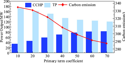
FIGURE 10. Impact of the primary term coefficient b on the carbon emissions and the output of CCHP and TP.
Conclusion
In this article, we constructed a low-carbon economic dispatch model of the IES considering the CEUC based on the DRPPM. Based on the example of an electricity–heat–cooling–gas IES, we verified the validity of the proposed models. In addition, the impact of CEUC on the low-carbon economic dispatch of the IES was analyzed. Relevant conclusions from this article are as follows:
First, compared with the fixed CEUC and the ladder-type CEUC, the CEUC based on the DRPPM proposed in this article has great significance in limiting the carbon emissions of the IES.
Second, this article analyzes the impact of the baseline value of the CEUC on the operation of the IES. The results show that within a certain range, the carbon emission cost, carbon emissions, and electricity purchasing cost of the IES decrease with the increase in the baseline value. The gas purchasing cost increases with the increase in the baseline value. It proves that the proposed model limits the carbon emissions of the system by penalizing high-carbon emission systems and rewarding low-carbon emission systems, which is conducive to achieving the goal of carbon neutrality.
Third, this study considers the impact of the primary term coefficient of the CEUC on the operation of the IES. The results indicate that within a certain range, as the primary coefficient increases, the output of TP and the carbon emissions gradually decrease,while the output of CCHP is gradually increasing.
Finally, for further study, future work can form the optimal dispatch model in more detail, such as how to set appropriate CEUC parameters, considering the uncertainties of the output of WT and PV and also considering the low-carbon economic dispatch of the integrated energy system with the best energy efficiency deserves further investigation.
Data Availability Statement
The original contributions presented in the study are included in the article/supplementary material; further inquiries can be directed to the corresponding author.
Author Contributions
WY and SZ designed the model and the computational framework, and analyzed the data. WY and SZ carried out the implementation and performed the calculations. SZ and LZ wrote the manuscript with input from all authors. ZX, XT, and SJ conceived the study and were in charge of overall direction and planning.
Conflict of Interest
The authors declare that the research was conducted in the absence of any commercial or financial relationships that could be construed as a potential conflict of interest.
Publisher’s Note
All claims expressed in this article are solely those of the authors and do not necessarily represent those of their affiliated organizations, or those of the publisher, the editors, and the reviewers. Any product that may be evaluated in this article, or claim that may be made by its manufacturer, is not guaranteed or endorsed by the publisher.
References
Abeysekera, M., Wu, J., Jenkins, N., and Rees, M. (2016). Steady State Analysis of Gas Networks with Distributed Injection of Alternative Gas. Appl. Energ. 164, 991–1002. doi:10.1016/j.apenergy.2015.05.099
Cheng, Y., Zhang, N., and Kang, C. (2017). Low‐carbon Economic Dispatch for Integrated Heat and Power Systems Considering Network Constraints. J. Eng. 2017 (14), 2628–2633. doi:10.1049/joe.2017.0846
Cui, Y., Zeng, P., Zhong, W., Cui, W., and Zhao, Y. (2021). Low-carbon Economic Dispatch of Electricity-Gas-Heat Integrated Energy System Based on Ladder-type Carbon Trading. Electric Power Automation Equipment 41 (03), 10–17. doi:10.16081/j.epae.202011030
He, L., Lu, Z., Zhang, J., Geng, L., Zhao, H., and Li, X. (2018). Low-carbon Economic Dispatch for Electricity and Natural Gas Systems Considering Carbon Capture Systems and Power-To-Gas. Appl. Energ. 224, 357–370. doi:10.1016/j.apenergy.2018.04.119
Li, G., Zhang, R., Jiang, T., Chen, H., Bai, L., and Li, X. (2017). Security-constrained Bi-level Economic Dispatch Model for Integrated Natural Gas and Electricity Systems Considering Wind Power and Power-To-Gas Process. Appl. Energ. 194, 696–704. doi:10.1016/j.apenergy.2016.07.077
Li H, H., Ye, Y., and Lin, L. (2021). Low-Carbon Economic Bi-level Optimal Dispatching of an Integrated Power and Natural Gas Energy System Considering Carbon Trading. Appl. Sci. 11 (15), 6968. doi:10.3390/app11156968
Li J, J., Zhang, N., Li, X., Zhang, Y., Zhang, Z., and Lv, Q. (2021). An Economic Dispatch Model of the Electricity-Heat Integrated Energy System Considering the Reserve Benefits of the Heat Storage. in 2021 4th International Conference on Energy, Electrical and Power Engineering (CEEPE), Chongqing, China, 1187–1193. doi:10.1109/ceepe51765.2021.9475800
Li, M., and Wang, Z. (2021). Modeling and Optimization of Integrated Energy System Based on Energy Circuit Theory. IEEJ Trans. Elec Electron. Eng. 16 (5), 696–703. doi:10.1002/tee.23349
Li, S., Guo, L., Zhang, P., Wang, H., Cai, Z., Zhu, X., et al. (2018). “Modeling and Optimization on Energy Efficiency of Urban Integrated Energy System,” in 2018 2nd IEEE Conference on Energy Internet and Energy System Integration (EI2). 1–6. doi:10.1109/ei2.2018.8582411
Li, Y., Tang, W., and Wu, Q. (2019). Modified Carbon Trading Based Low-Carbon Economic Dispatch Strategy for Integrated Energy System with CCHP. 2019 IEEE Milan PowerTech, 1–6. doi:10.1109/ptc.2019.8810482
Lingmin, C., Jiekang, W., Fan, W., Huiling, T., Changjie, L., and Yan, X. (2020). Energy Flow Optimization Method for Multi-Energy System Oriented to Combined Cooling, Heating and Power. Energy 211, 118536. doi:10.1016/j.energy.2020.118536
Liu, X., Geng, C., and Guan, J. (2020) “Day-ahead Economic Dispatch Including Photovoltaic Power Generation Cost,” in 2020 Chinese Automation Congress (CAC). 1369–1374. doi:10.1109/cac51589.2020.9326702
Liu, X., Wu, J., Jenkins, N., and Bagdanavicius, A. (2016). Combined Analysis of Electricity and Heat Networks. Appl. Energ. 162, 1238–1250. doi:10.1016/j.apenergy.2015.01.102
Lu, S., Gu, W., Zhang, C., Meng, K., and Dong, Z. (2020). Hydraulic-Thermal Cooperative Optimization of Integrated Energy Systems: A Convex Optimization Approach. IEEE Trans. Smart Grid 11 (6), 4818–4832. doi:10.1109/tsg.2020.3003399
Mancarella, P. (2014). “MES (Multi-energy Systems): An Overview of Concepts and Evaluation Models,” Energy. 65, 1–17. doi:10.1016/j.energy.2013.10.041
Martinez Cesena, E. A., and Mancarella, P. (2019). Energy Systems Integration in Smart Districts: Robust Optimisation of Multi-Energy Flows in Integrated Electricity, Heat and Gas Networks. IEEE Trans. Smart Grid 10 (1), 1122–1131. doi:10.1109/TSG.2018.2828146
Meibom, P., Hilger, K. B., Madsen, H., and Vinther, D. (2013). Energy Comes Together in Denmark: The Key to a Future Fossil-free Danish Power System. IEEE Power Energ. Mag. 11 (5), 46–55. doi:10.1109/mpe.2013.2268751
Ren, S., Wang, J., Gong, X., Gong, L., Peng, X., and Ao, J. (2019). “Low-carbon Economic Dispatching for Integrated Energy System Based on Coordinated Optimization of Power to Gas and Carbon Capture Power Plant,” in 2019 IEEE 3rd Conference on Energy Internet and Energy System Integration (EI2). 39–43. doi:10.1109/ei247390.2019.9061966
Tang, L., and Bao, Y. (2020, Electricity Gas Integrated Energy System Scheduling Model Considering Uncertainties and Multi-Storage of Both Electricity and Gas Systems,” in 2020 12th IEEE PES Asia-Pacific Power and Energy Engineering Conference (APPEEC), Nanjing, China, 1–5. doi:10.1109/appeec48164.2020.9220492
Wang, Y., Wang, Y., Huang, Y., Yang, J., Ma, Y., Yu, H., et al. (2019). “Operation Optimization of Regional Integrated Energy System Based on the Modeling of electricity-thermal-natural Gas Network,” Appl. Energ. 251, 113410. doi:10.1016/j.apenergy.2019.113410
Wu, Y. J., Liang, X. Y., Huang, T., Lin, Z. W., Li, Z. X., and Hossain, M. F. (2021). “A Hierarchical Framework for Renewable Energy Sources Consumption Promotion Among Microgrids through Two-Layer Electricity Prices,” Renew. Sust. Energ. Rev. 145, 111140. doi:10.1016/j.rser.2021.111140
Wu, Y., Lin, Z., Liu, C., Chen, Y., and Uddin, N. (2021). “A Bargaining Strategy-Based Game Model of Power Demand Response Considering Hydrogen-To-Electricity Conversion of Industrial Users,” IEEE Trans. Ind. Applicat. 1. doi:10.1109/tia.2021.3088769
Xiang, Y., Wu, G., Shen, X., Ma, Y., Gou, J., Xu, W., et al. (2021) “Low-carbon Economic Dispatch of Electricity-Gas Systems,” Energy. 226, 120267. doi:10.1016/j.energy.2021.120267
Xiaohui, Z., Xiaoyan, L., Jiaqing, Z., and Wenbo, G. (2019) “Electricity-gas‐integrated Energy Planning Based on Reward and Penalty Ladder‐type Carbon Trading Cost,” IET Generation, Transm. Distribution 13 (23), 5263–5270. doi:10.1049/iet-gtd.2019.0666
Xiaoyan, Y., Chunlin, G., Xuan, X., Dequan, H., and Zhou, M. (2017). “Research on Large Scale Electric Vehicles Participating in the Economic Dispatch of Wind and thermal Power System,” in 2017 China International Electrical and Energy Conference. 223–228. doi:10.1109/cieec.2017.8388450
Yang, C., Cong, Z., Guibo, D., Yicheng, L., Shipeng, Y., and Zhuo, S. (2021). Multi Objective Low Carbon Economic Dispatch of Power System Considering Integrated Flexible Operation of Carbon Capture Power Plant in 2021. Power Syst. Green Energ. Conf., 321–326. doi:10.1109/psgec51302.2021.9542780
Yang, D., Wang, M., Yang, R., Zheng, Y., and Pandzic, H. (2021). Optimal Dispatching of an Energy System with Integrated Compressed Air Energy Storage and Demand Response. Energy. 234, 121232. doi:10.1016/j.energy.2021.121232
Zhang G, G., Zhang, F., Zhang, L., Liang, J., Han, X., and Yang, Y. (2018). “Two-stage Robust Optimization Model of Day-Ahead Scheduling Considering Carbon Emissions Trading,” Proc. CSEE. 38, 5490–5499. doi:10.13334/j.0258-8013.pcsee.172405
Zhang, R., Chen, H., Li, X., Jiang, T., Li, G., and Ning, R. (2017), Low-carbon Economic Dispatch Model with Combined Wind-Storage System and Carbon Capture Power Plants. IEEE Power Energ. Soc. Gen. Meet.. 1–5. doi:10.1109/pesgm.2017.8274424
Zhang, R., Jiang, T., Li, X., Chen, H., and Li, G. (2018). “A Multi-Objective Approach for Low-Carbon Economic Dispatch with Carbon Capture Power Plants and Demand Response, IEEE Power Energ. Soc. Gen. Meet. (Pesgm). 1–5. doi:10.1109/pesgm.2018.8586555
Keywords: integrated energy system, economic dispatch, low-carbon, dynamic reward and penalty, pricing mechanism
Citation: Wu Y, Shi Z, Lin Z, Zhao X, Xue T and Shao J (2022) Low-Carbon Economic Dispatch for Integrated Energy System Through the Dynamic Reward and Penalty Carbon Emission Pricing Mechanism. Front. Energy Res. 10:843993. doi: 10.3389/fenrg.2022.843993
Received: 27 December 2021; Accepted: 24 January 2022;
Published: 17 February 2022.
Edited by:
Yujian Ye, Southeast University, ChinaReviewed by:
Rufeng Zhang, Northeast Electric Power University, ChinaJidong Wang, Tianjin University, China
Copyright © 2022 Wu, Shi, Lin, Zhao, Xue and Shao. This is an open-access article distributed under the terms of the Creative Commons Attribution License (CC BY). The use, distribution or reproduction in other forums is permitted, provided the original author(s) and the copyright owner(s) are credited and that the original publication in this journal is cited, in accordance with accepted academic practice. No use, distribution or reproduction is permitted which does not comply with these terms.
*Correspondence: Yingjun Wu, eWluZ2p1bnd1QGhvdG1haWwuY29t