 Lei Xu
 Hucheng Zhang1
 Chuan Wang
95% of researchers rate our articles as excellent or good
Learn more about the work of our research integrity team to safeguard the quality of each article we publish.
Find out more
ORIGINAL RESEARCH article
Front. Energy Res. , 28 March 2022
Sec. Process and Energy Systems Engineering
Volume 10 - 2022 | https://doi.org/10.3389/fenrg.2022.836456
This article is part of the Research Topic Design, Simulation and Optimization of Hydraulic Machinery View all 25 articles
To improve the efficiency of low-head pump device in the large-discharge and low-head domain, the hydraulic characteristics of vertical axial flow pump devices with different guide vane inlet angles were studied using computational fluid dynamics (CFD) and model test methods. The
Low-head pumping stations are widely used in fields such as water resource allocation, agriculture irrigation and drainage, urban drainage, and water environment improvement plans. The design heads of many of these pumping stations can be very low—that is, approximately 1.0 m (Qi et al., 2017; Yu et al., 2018). Affected by the pump model and motor, the pump devices used in these pumping stations often operate in low-head and large-discharge areas, which deviate from high-efficiency areas, resulting in the operational efficiency of the pumping stations being low (Wu et al., 2016).
The vertical axial flow pump device is arranged in the vertical direction, having the advantages of a simple structure, excellent heat dissipation, convenient installation and maintenance, and mature design and manufacture (Liu et al., 2008; Zhang et al., 2011); it is also widely applied in low-head pumping stations. It consists of an inlet conduit, impeller, guide vane, and outlet conduit, the hydraulic characteristics of the pump device being determined by these four components and their mutual matching. For example, the guide vane is used to recycle the kinetic energy of the water flow, its hydraulic design impacting the hydraulic performance of the pump and pump device. With a guide vane installed in the pump, water flow from the impeller outlet with tangential velocity is partly eliminated, and the water flow energy is converted into pressure energy, the recyclable rotation kinetic energy of the flow using the guide vane accounting for 10–15.7% of the total energy of the impeller outlet (Tang and Wang, 2006; Li et al., 2009). Compared to an axial flow pump with no guide vane, the efficiency can be improved by 5% when a guide vane is installed in the pump (Hu et al., 2008). The design of the guide vane clearly influences the position of the high-efficiency area for the pump (Zhou and Xu, 2007). Previous studies have shown that the pump device efficiency and discharge with the guide vane were higher than those for a pump device with no guide vane under design working conditions (Feng et al., 2012). To improve the efficiency of the axial flow pump, the influence of the guide vane angle adjustments on the hydraulic performance of the axial flow pump has been studied; the results have shown that the water head and efficiency of the axial flow pump increase when the guide vane is adjusted from the off-design condition, the pump efficiency improving by a maximum of 2.16%, and the stable operating range broadening (Qian et al., 2010; Qian et al., 2013).
The vertical axial flow pump device used in extra-low-head pumping stations usually works in a large-discharge area deviating from the high-efficiency area of the pump device, with the inlet angle of the guide vane not matching the direction of water flow at the impeller outlet. Consequently, the pump device efficiency can be improved by adjusting the inlet angle of the guide vane. Another function of the guide vane is that it can be used to fix the guide bearing in its wheel hub so that only the inlet angle of the guide vane can be adjusted.
Computational fluid dynamics (CFD) has been widely used in studies of the axial flow pump (Kan et al., 2021a; Al-Obaidi, 2021), submersible pump (Patil et al., 2019; Wang et al., 2021), centrifugal pump (Gonzalez and Santolaria, 2006; Wang et al., 2020a), the intake of pumping stations (Zhou et al., 2021) and the pump device (Kan et al., 2017), and other aspects (Wang et al., 2020b; Tang et al., 2021; Zawistowski and Kleiber, 2021; Zhang et al., 2021; Zhu et al., 2021), providing a convenient and effective method for their design and performance optimization. This study focuses on the vertical axial flow pump device and examines the influence of adjusting the guide vane inlet angle on energy performance of the pump device using three-dimensional turbulence flow numerical simulations. The results of the study are verified using a pump device model test.
Based on the parameters of a low-head pumping station, the influence of the guide vane inlet angle adjustment on energy performance of a vertical axial flow pump device was investigated. The parameters of the pumping station were as follows: the design head, maximum head, and minimum head were 1.08, 1.5, and 0.11 m respectively; the design discharge of one pump was 6.67 m3/s; the TJ04-ZL-07 pump model, used in the pump test in the same test-bed as for the South-to-North Water Diversion Project, was chosen (Liu et al., 2006); the prototype pump impeller diameter (
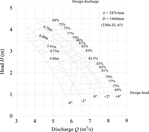
FIGURE 1. Comprehensive performance curve of the pump selection.
The elbow inlet and siphon outlet conduits were adopted in the pumping station, a drawing of the vertical axial flow pump device model being shown in Figure 2.

FIGURE 2. Drawing of the vertical axial-flow pump device. (A) Elevation, (B) Plan.
In the vertical axial flow pump device, the guide vane inlet continues the water flow from the impeller; thus, the inlet shape line design needs to meet the requirement that the stream flows into the guide vane smoothly. The stream then flows into the outlet conduit from the guide vane. Therefore, the outlet shape line design needs to meet the requirement that it efficiently adjusts the flow direction. From a structural design point of view, a guide bearing is installed in the guide vane wheel hub. Thus, the guide vane needs to meet the requirement of securing the guide bearing block.
Based on the guide vane hydraulic design and structure requirements, the guide vane can be divided into three sections—that is, the inlet, middle, and outlet sections, as shown in Figure 3, where
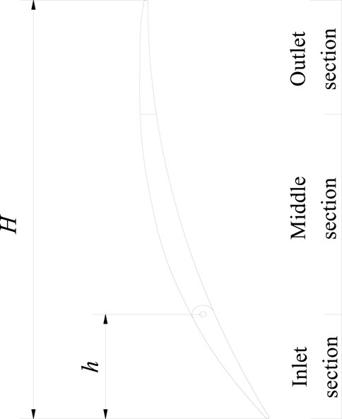
FIGURE 3. Schematic of guide vane subsection.
For an axial flow pump, the guide vane inlet angle (
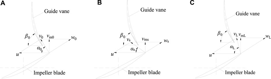
FIGURE 4. Matching relationships between the guide vane inlet angle and the impeller outlet flow direction. (A) Design discharge condition (
The guide vane inlet angle (
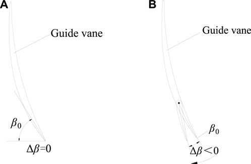
FIGURE 5. Rotation direction for adjusting guide vane inlet angle (A) Inlet angle of guide vane (
The Reynolds-averaged Navier-Stokes equations can be applied to solve the flow field in a vertical axial flow pump device, as follows:
where
There are many turbulence models for fluid flow simulations (Li et al., 2020; Kan et al., 2021b; Han et al., 2021). The Renormalization Group (RNG)
where
The computational domain of the three-dimensional turbulence flow simulations for the pump device comprises the forebay, inlet conduit, impeller, guide vane, outlet conduit, and outlet sump. The bodies of the inlet conduit, impeller, guide vane, and outlet conduit and the fluid flow within them are complex; thus, an unstructured mesh was adopted. The bodies and fluid flow of the forebay and outlet sump are, however, simple; therefore, a structured mesh was adopted. To obtain the most economical grid number, the grid independence was checked. Figure 6 shows the relationship between the pump device efficiency and grid number under the conditions of a blade angle of 0°, guide vane inlet angle adjustment of 0°, and discharge of 245 L/s. When the gird number exceeds approximately 3,240,000, the pump efficiency changes slightly. Consequently, the number of mesh cells for the vertical axial flow pump device was chosen to be 3,240,000, the grid numbers of each component being listed in Table 1. The value of y + affects the calculation accuracy: in this calculation the y + value of the impeller wall was 14.8. The computational domains and mesh generations for them are shown in Figure 7.
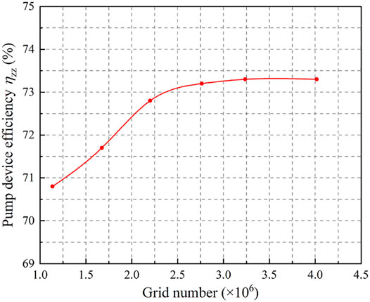
FIGURE 6. Relationship curve of pump device efficiency and grid number.

TABLE 1. Grid number of each component of the computational domain of the pump device.
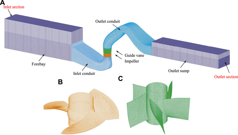
FIGURE 7. Computational domains and mesh generations of vertical axial flow pump device. (A) Pump device, (B) Impeller, (C) Guide vane.
The inlet boundary was set in the forebay, the velocity being uniformly distributed on the inlet boundary, and the flow direction being perpendicular to it. Because the discharge was known, the velocity inlet boundary condition was adopted. The outlet boundary was set at the outlet sump, far from the outlet section of the outlet conduit. The flow direction was perpendicular to the outlet boundary, the flow being fully developed there so that the outflow boundary condition could be adopted there. The bottom of the forebay and outlet sump, the side walls of the conduit, the surface of the guide vane, and the surface of the impeller blade were solid walls, the impeller blade surfaces being set as a rotation wall. The surfaces of the forebay and outlet sump were free water surfaces, the symmetry boundary being specified on the water surface.
In the numerical simulations, the SIMPLEC algorithm was used to solve the pressure-velocity coupling equations, the first-order upwind differencing scheme was used to solve the governing equations,
The numerical simulation conditions were as follows: the model pump impeller diameter (
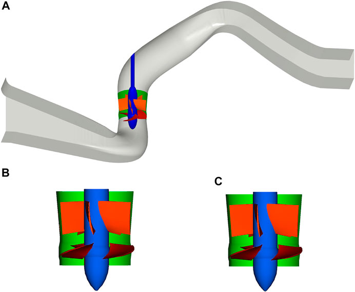
FIGURE 8. Perspective view of the model vertical axial flow pump device. (A) Pump Device, (B) Pump Segment (
The model vertical axial flow pump device included all flow conduits, the model inlet and outlet conduits being made of steel plates. An image of the model vertical axial flow pump device installed on the pumping station test bench at Yangzhou University is shown in Figure 9. The uncertainty of the pump device efficiency test in this experimental study was ±0.36%, the main test instruments of the test bench being listed in Table 2. Consistent with the numerical calculations, the energy performance test of the pump devices with inlet angle adjustments (
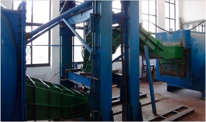
FIGURE 9. Image of vertical axial flow pump device model.
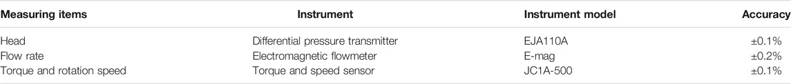
TABLE 2. Main test instruments of test bench.
The impeller blade angle was changed by adjusting the blade angle, while the guide vane inlet angle was changed by using two model guide vanes. The guide vane with an inlet angle adjustment (
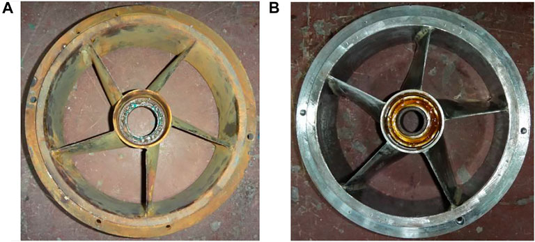
FIGURE 10. Images of model guide vanes with inlet angle adjustments
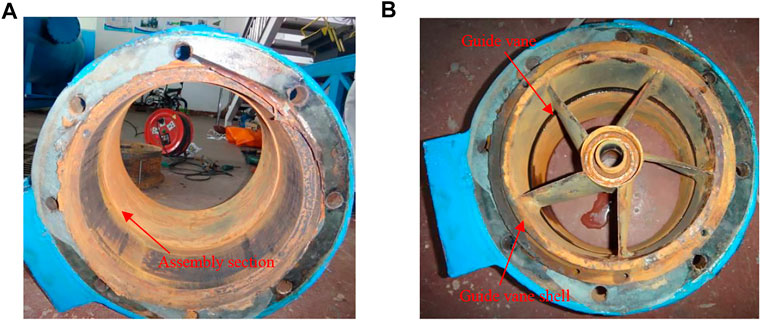
FIGURE 11. Images of the model guide vane assembly. (A) Guide vane shell, (B) Assembled guide vane.
Under the conditions of the impeller blade angles (
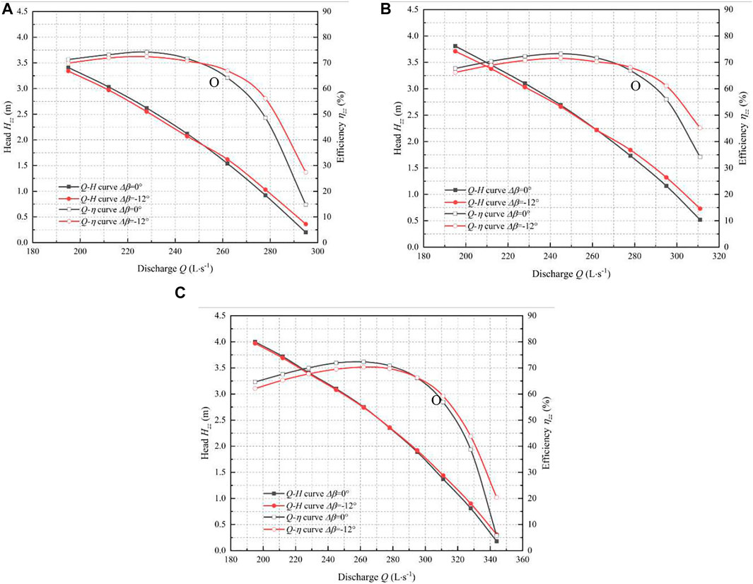
FIGURE 12. Numerical calculation results of
From Figure 10, it can be seen that there is an intersection point (O) between the two
To analyze the influence of the guide vane inlet angle adjustment, based on the composition of the pump, the relationship between the pump device efficiency (
where
The pump segment efficiency (
where
The three-dimensional turbulence flow in the pump device with a guide vane inlet angle adjustment (
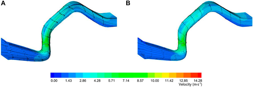
FIGURE 13. Pump device flow fields with
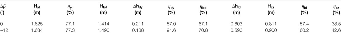
TABLE 3. Comparison of energy performance parameters of pump devices with
It can be seen that when
Under the conditions of an impeller angle of 0° and a discharge of 0.33 m3/s, the flow fields of the outer, middle, and inner rings of the guide vane when
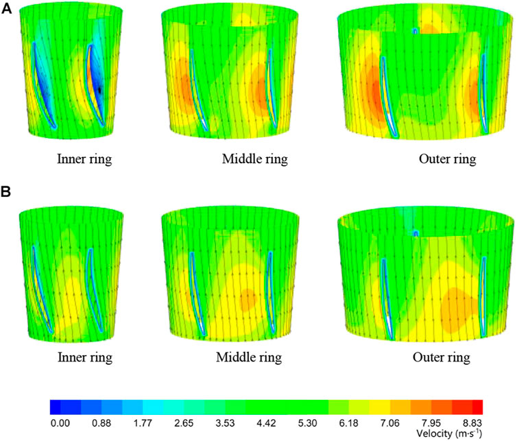
FIGURE 14. Guide vane flow fields with
A model test for the vertical axial flow pump device was conducted to verify the numerical computational results. Based on the test results, the
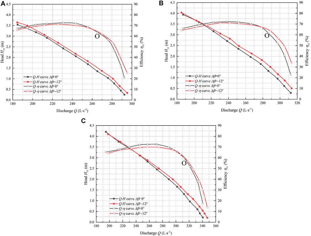
FIGURE 15. Model test results of
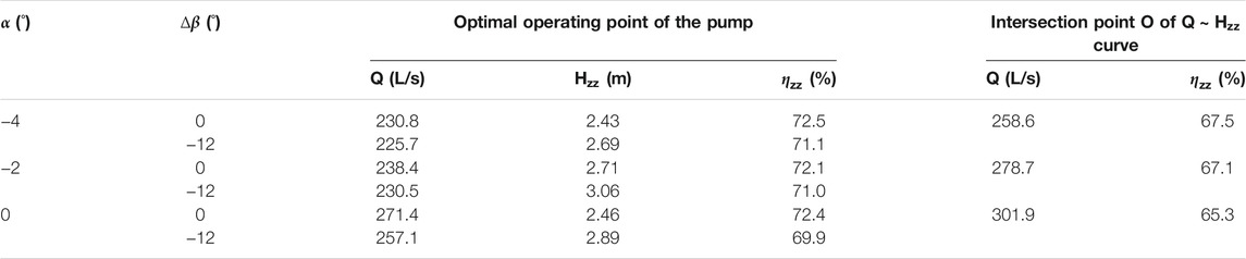
TABLE 4. Comparison of performance parameters at main operating points of the pump devices.
From the pump device model test results, it can be concluded that
1) There is an intersection point O between the two
2) When
3) When
A comparison between the numerical simulation and model test results of the pump device energy performance with an impeller blade angle (
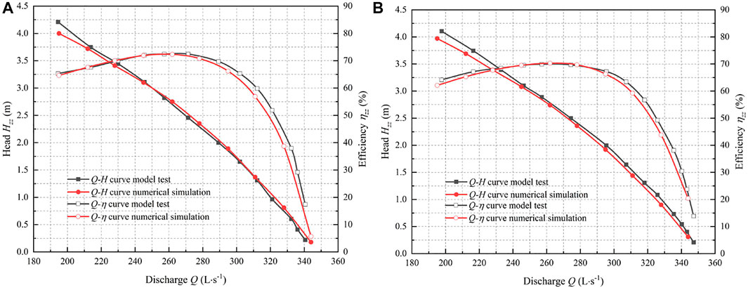
FIGURE 16. Comparison of model test and numerical calculation results of energy performance of the pump device with
1) The guide vane inlet angle had a significant impact on the energy performance of vertical axial flow pump device. When the guide vane inlet angle was adjusted in a clockwise direction, the pump device efficiency was reduced at the pump device optimal operating point, but its efficiency improved in low-head and large-discharge areas.
2) When the guide vane inlet angle did not match the direction of flow from the impeller outlet in the axial flow pump device, flow separation and a vortex were generated in the guide vane. By adjusting the guide vane inlet angle, the flow field could be significantly improved, the hydraulic loss of guide vane decreasing, and the energy performance of the axial flow pump device improving.
3) When the operating conditions of the low-head pump device are frequently in the large-discharge and low-head areas that deviate from the high-efficiency area due to limitations of the pump model or motor itself, these research results could be used to improve the energy performance of pump device in the low-head area.
The raw data supporting the conclusions of this article will be made available by the authors, without undue reservation.
LX, analysis, writing and revision; HZ, methodology and revision; CW, analysis and revision; DJ and WS, validation and revision; and WL and LL, data analysis and revision.
This work was supported by the National Natural Science Foundation of China (Grant No. 51309200, Grant No. 51779215), the High-tech Key Laboratory of Agricultural Equipment and Intelligentization of Jiangsu Province, Key Laboratory of Modern Agricultural Equipment and Technology (Jiangsu University), the Ministry of Education (NZ201604), and the Jiangsu South-to-North Water Diversion Technology R and D Project (JSNSBD202105).
Author WS is employed by Jiangsu Water Supply Co., Ltd. In the Eastern Route of the S-to-N Water Diversion Project.
The remaining authors declare that the research was conducted in the absence of any commercial or financial relationships that could be construed as a potential conflict of interest.
All claims expressed in this article are solely those of the authors and do not necessarily represent those of their affiliated organizations, or those of the publisher, the editors and the reviewers. Any product that may be evaluated in this article, or claim that may be made by its manufacturer, is not guaranteed or endorsed by the publisher.
Al-Obaidi, A. R. (2021). Analysis of the Effect of Various Impeller Blade Angles on Characteristic of the Axial Pump with Pressure Fluctuations Based on Time- and Frequency-Domain Investigations. Iran J. Sci. Technol. Trans. Mech. Eng. 45, 441–459. doi:10.1007/s40997-020-00392-3
Caruso, F., and Meskell, C. (2021). Effect of the Axial gap on the Energy Consumption of a Single-Blade Wastewater Pump. Proc. Inst. Mech. Eng. A: J. Power Energ. 235, 432–439. doi:10.1177/0957650920927366
Feng, J., Zheng, Y., and Luo, X. (2012). Effects of Exit Guide Vane on Performance of Axial-Flow Pump Device. Water Resour. Power 30, 126–128. doi:10.3969/j.issn.1000-7709.2012.08.037
González, J., and Santolaria, C. (2006). Unsteady Flow Structure and Global Variables in a Centrifugal Pump. J. Fluids Eng. Trans. ASME. 128, 937–946. doi:10.1115/1.2234782
Han, Y., Zhou, L., Bai, L., Shi, W., and Agarwal, R. (2021). Comparison and Validation of Various Turbulence Models for U-bend Flow with a Magnetic Resonance Velocimetry experiment. Phys. Fluids 33. doi:10.1063/5.0073910
Hu, J., Huang, S., and Wang, P. (2008). Research on Hydrodynamic Characteristics of Axial Waterjet Pump with Guide Vane. J. Hydroelectr. Eng. 27, 32–36. doi:10.3969/j.issn.1003-1243.2008.01.007
Jafarzadeh, B., Hajari, A., Alishahi, M. M., and Akbari, M. H. (2011). The Flow Simulation of a Low-Specific-Speed High-Speed Centrifugal Pump. Appl. Math. Model. 35, 242–249. doi:10.1016/j.apm.2010.05.021
Jiao, W., Cheng, L., Xu, J., and Wang, C. (2019). Numerical Analysis of Two-phase Flow in the Cavitation Process of a Waterjet Propulsion Pump System. Processes 7, 690. doi:10.3390/pr7100690
Kan, K., Chen, H., Zheng, Y., Zhou, D., Binama, M., and Dai, J. (2021a). Transient Characteristics during Power-Off Process in a Shaft Extension Tubular Pump by Using a Suitable Numerical Model. Renew. Energ. 164, 109–121. doi:10.1016/j.renene.2020.09.001
Kan, K., Yang, Z., Lyu, P., Zheng, Y., and Shen, L. (2021b). Numerical Study of Turbulent Flow Past a Rotating Axial-Flow Pump Based on a Level-Set Immersed Boundary Method. Renew. Energ. 168, 960–971. doi:10.1016/j.renene.2020.12.103
Kan, K., Zheng, Y., Fu, S., Liu, H., Yang, C., and Zhang, X. (2017). Dynamic Stress of Impeller Blade of Shaft Extension Tubular Pump Device Based on Bidirectional Fluid-Structure Interaction. J. Mech. Sci. Technol. 31, 1561–1568. doi:10.1007/s12206-017-0303-1
Li, X., Shen, T., Li, P., Guo, X., and Zhu, Z. (2020). Extended Compressible thermal Cavitation Model for the Numerical Simulation of Cryogenic Cavitating Flow. Int. J. Hydrogen Energ. 45, 10104–10118. doi:10.1016/j.ijhydene.2020.01.192
Li, Z., Yang, M., and Wang, X. (2009). Experimental Study of Guide Vane Influence on Performance of Axial-Flow Pump. Drain. Irrig. Mach. 27, 15–18.
Liu, J., Gong, Y., and Wang, Y. (2008). Influence of Pump Diameter on Hydraulic Loss of Vertical Pump Device. S. North Water Transfers Water Sci. Technol. 6, 67–69. doi:10.13476/j.cnki.nsbdqk.2008.05.026
Liu, N., Wang, Y. S., and Zhang, G. (2006). Model Pump Test on the Same Test-Bed for the South-To-North Water Diversion. Beijing, China: China Water Power Press.
Patil, A., Sundar, S., Delgado, A., and Gamboa, J. (2019). CFD Based Evaluation of Conventional Electrical Submersible Pump for High-Speed Application. J. Petrol. Sci. Eng. 182. doi:10.1016/j.petrol.2019.106287
Qi, L., Zhang, Y., and Zhang, G. (2017). Model Test and Analysis of Pump Device of Miyun Reservoir Regulation and Storage Project of Incoming Water from South-To-North Transfer Project. Yellow River 6, 133–137. doi:10.3969/j.issn.1000-1379.2017.06.031
Qian, J., Gao, Z., Liu, B., and Jin, Z. (2018). Parametric Study on Fluid Dynamics of Pilot-Control Angle globe Valve. J. Fluids Eng. 140. doi:10.1115/1.4040037
Qian, Z., Wang, F., Wang, Z., and Zhou, W. (2013). Experimental Study on Hydraulic Performance of Saddle Zone in Axial-Flow Pump with Adjustable Guide Vane. J. Drain. Irrig. Mach. Eng. 31, 461–465. doi:10.3969/j.issn.1674.8530.2013.06.001
Qian, Z., Wang, Y., Huai, W., and Lee, Y. (2010). Numerical Simulation of Water Flow in an Axial Flow Pump with Adjustable Guide Vanes. J. Mech. Sci. Technol. 24, 971–976. doi:10.1007/s12206-010-0212-z
Tang, F., and Wang, G. (2006). Influence of Outlet Guide Vanes upon Performances of Waterjet Axial-Flow Pump. J. Ship Mech. 6, 19–26. doi:10.3969/j.issn.2006.06.003
Tang, S., Zhu, Y., and Yuan, S. (2021). An Improved Convolutional Neural Network with an Adaptable Learning Rate towards Multi-Signal Fault Diagnosis of Hydraulic Piston Pump. Adv. Eng. Inform. 50. doi:10.1016/j.aei.2021.101406
Wang, H. L., Hu, Q. X., Yang, Y., and Wang, C. (2021). Performance Differences of Electrical Submersible Pump under Variable Speed Schemes. Int. J. Simul. Model. 20, 76–86. doi:10.2507/ijsimm20-1-544
Wang, H., Long, B., Wang, C., Han, C., and Li, L. (2020a). Effects of the Impeller Blade with a Slot Structure on the Centrifugal Pump Performance. Energies 13, 1628. doi:10.3390/en13071628
Wang, H., Qian, Z., Zhang, D., Wang, T., and Wang, C. (2020b). Numerical Study of the Normal Impinging Water Jet at Different Impinging Height, Based on Wray-Agarwal Turbulence Model. Energies 13, 1744. doi:10.3390/en13071744
Wu, H., Tian, Y., Liao, W., Liu, B., and Song, W. (2016). Pumping Device Performance Analysis Based on the Miyun Storage Project of Cascade Pumping Stations. China Rural Water Hydropower. 11, 178–182.
Yu, J., Chen, Y., Zhu, Y., Lv, B., and Sun, P. (2018). Study on Pump Type Selection for Extra-low Head Pumping Station with Large Difference between Average and Highest Heads. Water Resour. Hydropower Eng. 49, 68–76. doi:10.13928/j.cnki.wrahe.2018.05.011
Zawistowski, T., and Kleiber, M. (2017). Gap Flow Simulation Methods in High Pressure Variable Displacement Axial Piston Pumps. Arch. Computat Methods Eng. 24, 519–542. doi:10.1007/s11831-016-9180-5
Zhang, L., Li, Y., Zong, L., Duan, Z., and Hua, X. (2011). Type Selection and Hydraulic Optimization of Vertical Axial-Flow Pump Assembly in Changgou Pumping Station of the East Route of South-To-North Water Transfer Project. S. North Water Transfers Water Sci. Technol 9, 15–18. doi:10.3724/SP.J.1201.2011.05015
Zhang, L., Wang, C., Zhang, Y., Xiang, W., He, Z., and Shi, W. (2021). Numerical Study of Coupled Flow in Blocking Pulsed Jet Impinging on a Rotating wall. J. Braz. Soc. Mech. Sci. Eng. 43, 508. doi:10.1007/s40430-021-03212-0
Zhou, J., Zhao, M., Wang, C., and Gao, Z. (2021). Optimal Design of Diversion Piers of Lateral Intake Pumping Station Based on Orthogonal Test. Shock and Vibration 2021, 1–9. doi:10.1155/2021/6616456
Zhou, Y., and Xu, H. (2007). The Influence of Diffuser on the Function of the Axial-Flow Pump. Water Conserv. Electr. Power Mach. 29, 28–29. doi:10.3969/j.issn.1674-1951.2007.09.010
Keywords: axial-flow pump device, guide vane, inlet angle, hydraulic characteristics, numerical simulation, model test
Citation: Xu L, Zhang H, Wang C, Ji D, Shi W, Lu W and Lu L (2022) Hydraulic Characteristics of Axial Flow Pump Device With Different Guide Vane Inlet Angles. Front. Energy Res. 10:836456. doi: 10.3389/fenrg.2022.836456
Received: 15 December 2021; Accepted: 24 January 2022;
Published: 28 March 2022.
Edited by:
Xiaojun Li, Zhejiang Sci-Tech University, ChinaReviewed by:
Kan Kan, College of Energy and Electrical Engineering, ChinaCopyright © 2022 Xu, Zhang, Wang, Ji, Shi, Lu and Lu. This is an open-access article distributed under the terms of the Creative Commons Attribution License (CC BY). The use, distribution or reproduction in other forums is permitted, provided the original author(s) and the copyright owner(s) are credited and that the original publication in this journal is cited, in accordance with accepted academic practice. No use, distribution or reproduction is permitted which does not comply with these terms.
*Correspondence: Lei Xu, bGVpeHVAeXp1LmVkdS5jbg==
Disclaimer: All claims expressed in this article are solely those of the authors and do not necessarily represent those of their affiliated organizations, or those of the publisher, the editors and the reviewers. Any product that may be evaluated in this article or claim that may be made by its manufacturer is not guaranteed or endorsed by the publisher.
Research integrity at Frontiers
Learn more about the work of our research integrity team to safeguard the quality of each article we publish.