 Dongxu Zhang
 Minfu Zhao
 Peng Liang
95% of researchers rate our articles as excellent or good
Learn more about the work of our research integrity team to safeguard the quality of each article we publish.
Find out more
ORIGINAL RESEARCH article
Front. Energy Res. , 17 March 2022
Sec. Nuclear Energy
Volume 10 - 2022 | https://doi.org/10.3389/fenrg.2022.835224
This article is part of the Research Topic Experimental and Simulation Research on Nuclear Reactor Thermal-Hydraulics View all 15 articles
The printed circuit heat exchanger (PCHE) is the key equipment of the supercritical carbon dioxide Brayton cycle applied to sodium cooled fast reactor. It is required that the equipment not only can operate in high temperature and high pressure environment but also has high efficiency and compact structure. The China Institute of Atomic Energy has carried out the research on a sodium-supercritical carbon dioxide PCHE and has designed and manufactured a heat exchanger prototype with the heat transfer power of 50 kW. In addition, the supercritical carbon dioxide test loop and sodium test loop have been built to test the performance of the heat exchanger prototype. The conclusions are as follows: 1) The heat exchange power of the heat exchanger under rated working condition is 54.2 kW, and the deviation is around 8%, which meets the design requirements; 2) With the increase of the flow ratio of sodium to carbon dioxide, the temperature difference at the high temperature end decreases, and the temperature difference at the low temperature end increases; 3) The change of flow rate of the carbon dioxide has a great influence on heat transfer power; 4) The total heat transfer coefficient of the heat exchanger increases with the increase of the pressure of carbon dioxide; when the pressure increases from 15.5 to 20 MPa, the total heat transfer coefficient increases by 12.8%.
The supercritical carbon dioxide Brayton cycle system is one of the most promising power conversion systems, which has the advantages of clean working fluid, good fluidity, high efficiency, high energy density, and small size of the equipment. It could eliminate the safety problems caused by sodium–water reaction, so it extremely has the engineering application prospects in sodium-cooled fast reactor (Wang et al., 2019).
As a cycle working fluid, the supercritical carbon dioxide has the characteristics of good fluidity and high density, which can reduce the size of key equipment, such as heat exchanger and compressor (Dostal, 2004; Yang, 2014). The heat exchanger is the key equipment of the supercritical carbon dioxide Brayton cycle, and its heat transfer performance has a direct influence on the efficiency of the reactor cycle system. The printed circuit heat exchanger (PCHE) is used in the supercritical carbon dioxide Brayton cycle system, which is a compact heat exchanger with the characteristics of less leakage and high efficiency, and it can be used in high-temperature and high-pressure conditions (Yu et al., 2017).
Ngo et al. (2006) had analyzed the thermal hydraulic performance of PCHE with the S-type fin structure with water and supercritical carbon dioxide as working fluid. They found that, compared with the heat exchanger in the heat pump system, the volume of the PCHE with S-type fin structure was reduced by 3.3 times, the pressure drop of the carbon dioxide side was reduced by 37%, and the water side was reduced by 10 times.
Kim et al. (2012) had studied the thermal–hydraulic performance of helium in PCHE in the range of 350˂Re˂1,200. The hot side temperature was 25–550°C, the cold side temperature was 20–100°C, the test pressure was 1.5–1.9 MPa, and the mass flow rate was 40–100 kg/h. According to the inlet and outlet parameters of the heat exchanger, a correlation equation between Fanning’s friction factor and Nusselt number was proposed. The numerical results with FLUENT were consistent with the experimental results. According to the CFD calculation, the Nusselt number correlation equation on the basis of the local average pitch was proposed, which was better than the correlation equation obtained by the experimental method. In addition, Kim and No. (2011) had studied the thermal–hydraulic performance of PCHE in high temperature gas cooled reactor with helium–water working fluid in the laminar flow range. Then, the numerical results had been compared with the experimental results, and a unified correlation between Fanning’s friction factor and Nusselt number suitable for different working fluids was proposed.
Baik et al. (2017) developed the PCHE design code on the basis of MATLAB to accurately reflect the real gas effect near the critical point and carried out performance tests under various CO2 conditions, including gas phase, liquid phase, and supercritical phase. The test temperature and pressure were 26–43°C and 7.3–8.6 MPa, respectively, with Reynolds number range of 15,000–100,000 and Prandtl number range of 2–33. They found that the designed PCHE showed satisfying heat transfer performance under both on-design and off-design conditions, which had more than 90% effectiveness within 200-mm small core. The correlations of friction factor and heat transfer were proposed.
Liu et al. (2020) designed and built the PCHE prototype of the straight channels and carried out experimental research on local thermal and hydraulic performance under wide operating conditions. The hot side system pressure was 7.53–11.97 MPa and the cold side was 0.14–0.18 MPa; the fluid temperature on the hot side was 26.40–121.27°C and that on the cold side was 23.10–60.96°C; the mass flow on the hot side was 50.03–780.11 kg/(m2 s) and that on the cold side was 94.64–282.27 kg/(m2 s). New correlations between convective heat transfer coefficient and Fanning friction coefficient were proposed, which had been applied in an analytical code for designing PCHE. The results showed good agreements between predictions and experimental bulk-fluid temperature along the axis, and the predicted and observed locations of the pinch point also showed good uniformity.
Cheng et al. (2020) experimentally studied the performance of a 100-kW PCHE for a module of a full-scale MW pre-cooler with water and SCO2 as working medium and mainly studied the effects of inlet Reynolds number and temperature on both sides of the heat exchanger on heat transfer, pressure drop, and efficiency of the heat exchanger. They found that the total heat transfer coefficient and heat transfer rate increased with the increase of inlet Reynolds number. With the increase of Rei on the hot side and cold side of PCHE by 69.48% and 79.61%, the overall heat transfer coefficient increased by 17.91% and 19.02%, respectively. Because the higher inlet Reynolds number increased the disturbance of fluid in the channel, the pressure drop increased with the increase of inlet Reynolds number. Higher efficiency could be obtained by increasing the inlet Reynolds number of water or decreasing the inlet Reynolds number of SCO2.
Recently, a relevant research on the supercritical carbon dioxide power cycle systems has been conducted in the China Institute of Atomic Energy, including the development of a prototype with sodium-supercritical carbon dioxide of PCHE and a facility has been set up to test the performance of the PCHE.
The heat exchanger is the key equipment of the supercritical carbon dioxide Brayton cycle. The designed power of the heat exchanger is 50 kW. The core of the heat exchanger is formed by carbon dioxide plates and sodium plates, which is arranged alternately with one layer of sodium plate and two layers of carbon dioxide plates. The configuration is shown in Figure 1. The sodium plate is composed of circular channels with the diameter of 4 mm and the channel spacing of 6 mm. The circular channels are formed by two semi-circular channels. Each sodium plate has 40 channels with the thickness of 3 mm. The carbon dioxide plate is composed of semicircular channels with the diameter of 1.5 mm and the channel spacing of 2.5 mm. Each carbon dioxide plate has 26 channels with the thickness of 1.5 mm. The core size is 110°mm × 273°mm × 224°mm, and the final structure of the heat exchanger is shown in Figure 2.
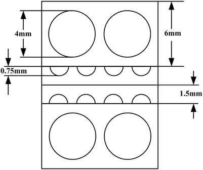
FIGURE 1. Internal structure of the PCHE.
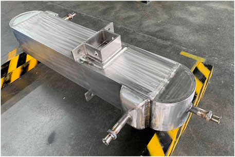
FIGURE 2. Picture of PCHE prototype with heat transfer power of 50 kW.
The performance verification test system of the heat exchanger consists of two test loops, namely, the supercritical carbon dioxide test loop and the sodium test loop, which provides test condition for each side. The test system is shown in Figure 3.
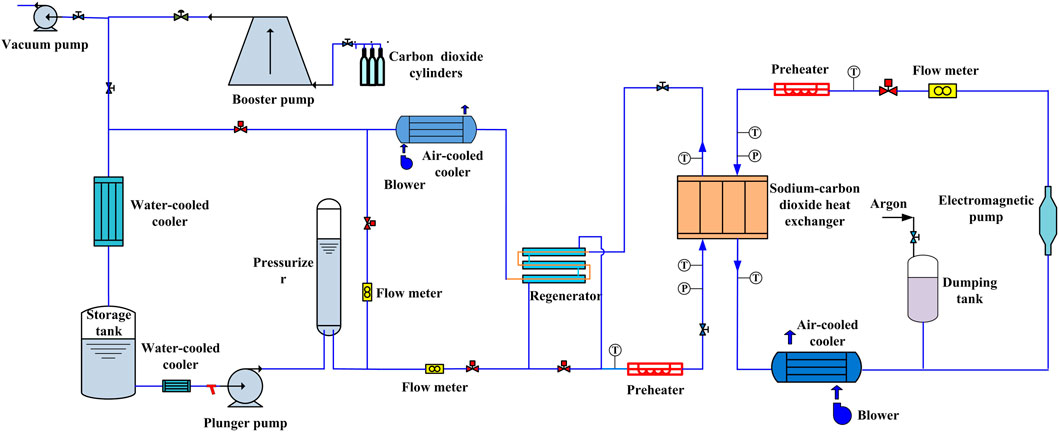
FIGURE 3. Test system of the performance of the prototype.
The carbon dioxide is supplied by a plunger pump with a maximum pressure of 25 MPa and a flow rate of 2 m3/h. The carbon dioxide flows through the pressurizer and regenerator, is heated by a preheater with a capacity of 120-kW DC, and then enters the heat exchanger. The carbon dioxide exchanges heat with the sodium in the heat exchanger. After the high-temperature carbon dioxide flows out of the heat exchanger, it is cooled by the air-cooled cooler with the capacity of 70 kW, is reduced the pressure by the pressure regulating valve and then further cooled by the water-cooled cooler with the capacity of 65 kW, and finally enters the storage tank. The pressure fluctuation generated during the operations is maintained and absorbed by the pressurizer in the test loop.
The sodium test loop is driven by an electromagnetic pump with a maximum flow rate of 1 m3/h, and the mass flow rate is measured by the electromagnetic flow meter. The sodium is heated by the preheater with a capacity of 100-kW AC and flows through the heat exchanger. The sodium exchanges heat with the carbon dioxide in the heat exchanger. The sodium is finally cooled by the air-cooled cooler with the capacity of 50 kW and returns to the inlet of the electromagnetic pump. The pressure fluctuation and the thermal expansion of the working fluid are maintained and absorbed by the dumping tank in the test loop.
The flow rate of the carbon dioxide is measured by a mass flow meter with the measuring range of 0–0.5 kg/s and the accuracy of ±0.2%, and the sodium is measured by an electromagnetic flow meter with the measuring range of 0–0.33 kg/s and the accuracy of ±0.5%. The pressures are measured by pressure sensors with the measuring range of 0–25 MPa and the accuracy of ±0.1% at the inlet and outlet of the heat exchanger. In addition, the inlet and outlet temperatures of the heat exchanger are measured by the thermocouples with the measuring range of 0–600°C and the accuracy of ±0.5°C. All the parameters are recorded by a data acquisition system.
In the test, the sodium side pressure was 0.1–0.2 MPa, the flow rate was 0.17–0.30 kg/s, and the inlet temperature was 490–520°C; the carbon dioxide side pressure was 15, 18, and 20 MPa, the flow rate was 0.21–0.24 kg/s, and the inlet temperature was 310–340°C. A total of 18 groups of steady-state experimental data were obtained.
During the test operation, the inlet pressure, mass flow rate, inlet and outlet temperature of the two sides, and the wall temperature of the heat exchanger were recorded. The experimental data were recorded every 1 s in the test system. Take the rated condition for an example, 1,800 continuous data points in the stable period are selected, and the average value of these data points is taken as the test data. The reduced test results are shown in Table 1.
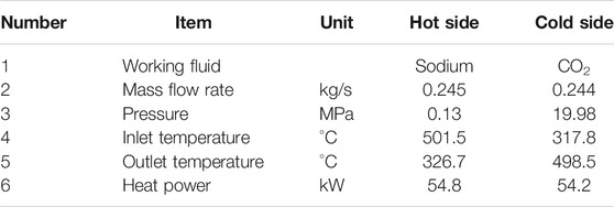
TABLE 1. Test results under rated condition.
The calculation equations of the heat transfer power on sodium side and carbon dioxide side are as follows,
where
The uncertainty in the test mainly comes from the systematic error and instrument accuracy, and the accuracy of instrument has been introduced above. The systematic error mainly includes the following aspects: 1) The temperature measuring points are arranged on the inlet and outlet pipes of the heat exchanger, and there is a certain deviation between the actual temperature and the measured value; 2) Because of heat dissipation, the heat transfer power on the sodium side will be greater than that on the carbon dioxide side, but the heat insulation is good, so that there is little difference between them; 3) The data acquisition system may produce errors in the process of signal conversion. By analyzing the test results under rated working condition, it can be seen that the accuracy of the pressure sensor is high; within the range of pressure error, the enthalpy of carbon dioxide changes little; and the main error is caused by temperature. Within the deviation of 0.5°C, the enthalpy difference is 0.62 kJ; according to the error transmission, the maximum error on the carbon dioxide side is 0.53 kW at 20 MPa. The specific heat of sodium is 1.33 kJ/(kg °C) at 501.5°C and 1.40 kJ/(kg°C) at 326.7°C; there is little difference between them, and the average value of the specific heat within the test temperature range is reasonable. In addition, considering the flow measurement error and temperature error, the maximum error on the sodium side is 0.54 kW. Considering the system error and heat dissipation, the heat transfer power on sodium side is 54.8 kW and that on carbon dioxide side is 54.2 kW, the relative error on both sides is within 1%. The difference of heat transfer power on both sides is 0.6 kW, the deviation of the heat balance is 1.09%, and the heat balance is good.
The heat transfer power of the heat exchanger under rated condition is 54.2 kW. According to the inlet and outlet temperature measured in the test, the total heat transfer coefficient of the heat exchanger under rated condition can be calculated. The calculation equations are as follows:
where
The heat transfer area is 7.3 m2, and taking the inlet and outlet temperatures measured in the test into the equation, the total heat transfer coefficient of the heat exchanger under rated condition is 1,264 W/(m2°C), and the designed total heat transfer coefficient is 1,301 W/(m2°C); the difference between the two values is small.
In order to study the temperature change of the fluid along the flow channel, 18 temperature measuring points were arranged on the three walls of the heat exchanger along the flow direction. In addition, temperature measuring points were arranged at the outlet of the heat exchanger to measure the temperature non-uniformity. All the temperature measuring points were arranged on the surface of the heat exchanger. The arrangement of the wall temperature measuring points is shown in Figure 4. Figure 5 shows the variation of the wall temperatures of the heat exchanger with the axial position.
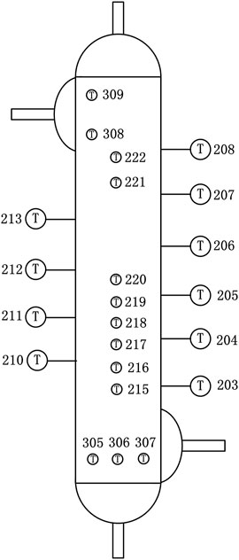
FIGURE 4. Wall temperature layout of the heat exchanger.
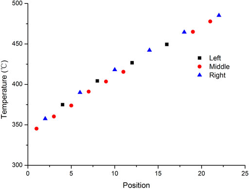
FIGURE 5. Wall temperature under rated working condition.
As can be seen from Figure 5, the wall temperature of the heat exchanger increases linearly in the axial direction and along the flow direction of carbon dioxide. The inlet wall temperatures T305 ∼ 307 of carbon dioxide side are 332.5, 330.4, and 328.7°C, respectively, and the outlet wall temperatures T308 and T309 of carbon dioxide side are 486.7 and 496.6°C, respectively. Because of the influence of cross flow, the temperature is non-uniform.
The test was conducted not only under rated condition but also under some other different experimental conditions. As shown in Figure 6, it shows the effect of different flow rates of sodium and carbon dioxide on the performance of the heat exchanger when the pressure of carbon dioxide is 15 MPa. The x-axis is the ratio of mass flow of sodium to carbon dioxide. As the flow ratio increases, the temperature difference at the inlet end on the sodium side (high temperature end) gradually decreases, and the temperature difference at the outlet end on the sodium side (low temperature end) gradually increases. This is because when the mass flow rate of sodium is small, the sodium side is cooled sufficiently, so the sodium outlet temperature is close to the carbon dioxide inlet temperature. When the mass flow rate of sodium is large, the carbon dioxide is heated sufficiently so that the carbon dioxide outlet temperature is close to the sodium inlet temperature. As can be seen from Figure 6, when the mass flow rate of carbon dioxide is constant, the heat transfer power of the heat exchanger changes little with the flow rate of sodium. However, the flow rate of sodium is constant, and the heat transfer power changes significantly with the flow rate of carbon dioxide.
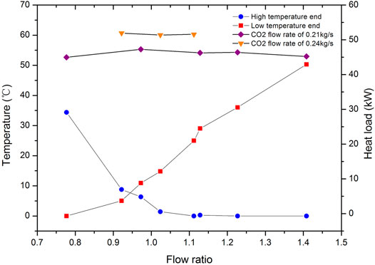
FIGURE 6. Variation of temperature difference and heat transfer power with the flow ratio.
The pressure influence of the carbon dioxide side on the heat transfer performance is also studied at same conditions. The results show that the heat transfer coefficient of the heat exchanger increases with the pressure increase of the carbon dioxide; when the pressure increases from 15.5 to 20 MPa, the heat transfer coefficient increases by 12.8%, as shown in Table 2. This is caused by the different physical properties of carbon dioxide at different pressures. Figure 7 shows the variation law of thermal conductivity of carbon dioxide under different pressures. It can be seen that the higher the pressure, the greater the thermal conductivity, so the greater the heat transfer coefficient under the same conditions.

TABLE 2. Pressure effect on the heat transfer performance.
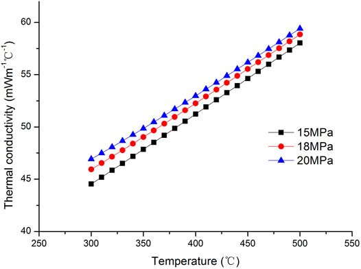
FIGURE 7. The thermal conductivity of CO2 varies with pressure and temperature.
In this paper, the experimental research on the prototype of sodium-supercritical carbon dioxide PCHE has been carried out under the rated condition and other different conditions. The influence of different parameters on the heat exchanger is studied, and the conclusions are as follows:
1) Under the rated condition, the heat transfer power is 54.2 kW, and the deviation is around 8%. The test results show that the prototype of the heat exchanger meets the design requirements;
2) The temperature difference of the high temperature end decreases with the increase of the flow ratio of sodium to carbon dioxide, and the temperature difference of the low temperature end increases with the increase of the flow ratio;
3) When the flow rate of sodium was constant, the heat transfer power changes significantly with the flow rate of carbon dioxide, the flow rate of carbon dioxide has a great effect on the heat transfer power; when the flow rate of carbon dioxide is constant, the effect of flow rate of sodium on heat transfer power is relatively small;
4) Under the same working conditions, the heat transfer coefficient of the heat exchanger increases with the increase of pressure of the carbon dioxide; when the pressure increases from 15.5 to 20 MPa, the total heat transfer coefficient increases by 12.8%.
The original contributions presented in the study are included in the article/Supplementary Material, further inquiries can be directed to the corresponding author.
DZ was mainly responsible for the test operation, data analysis, and paper drafting. MZ was mainly contributed to the data analysis. PL was mainly responsible for the numerical calculation. WL was mainly responsible for paper review and modification.
The present investigation is supported by the National Key R and D Program of China (2018YFE0116100).
The authors declare that the research was conducted in the absence of any commercial or financial relationships that could be construed as a potential conflict of interest.
All claims expressed in this article are solely those of the authors and do not necessarily represent those of their affiliated organizations or those of the publisher, the editors and the reviewers. Any product that may be evaluated in this article, or claim that may be made by its manufacturer, is not guaranteed or endorsed by the publisher.
The authors wish to thank the CIAE team who performed the test verification under rated condition and different other conditions and provided the test data for analysis.
Baik, S., Kim, S. G., Lee, J., and Lee, J. I. (2017). Study on CO2 - Water Printed Circuit Heat Exchanger Performance Operating under Various CO₂ Phases for S-CO₂ Power Cycle Application. Appl. Therm. Eng. 113, 1536–1546. doi:10.1016/j.applthermaleng.2016.11.132
Cheng, K., Zhou, J., Zhang, H., Huai, X., and Guo, J. (2020). Experimental Investigation of thermal-hydraulic Characteristics of a Printed Circuit Heat Exchanger Used as a Pre-cooler for the Supercritical CO2 Brayton Cycle. Appl. Therm. Eng. 171, 115116. doi:10.1016/j.applthermaleng.2020.115116
Dostal, V. (2004). “A Supercritical Carbon Dioxide Cycle for Next Generation Nuclear Reactors. Doctoral Dissertation. Cambridge, MA(USA): MIT.
Kim, I., No, H., Lee, J., and Jeon, B. (2012). Thermal Hydraulic Performance Analysis of the Printed Circuit Heat Exchanger Using a Helium Test Facility and CFD Simulations. Nucl. Eng. Des. 239 (11), 2399–2408. doi:10.1016/j.nucengdes.2009.07.005
Kim, I., and No, H. (2011). Thermal Hydraulic Performance Analysis of a Printed Circuit Heat Exchanger Using a Helium–Water Test Loop and Numerical Simulations. Appl. Therm. Eng. 31 (17-18), 4064–4073. doi:10.1016/j.applthermaleng.2011.08.012
Liu, S.-h., Huang, Y.-p., Wang, J.-f., Liu, R.-l., and Zang, J.-g. (2020). Experimental Study of thermal-hydraulic Performance of a Printed Circuit Heat Exchanger with Straight Channels. Int. J. Heat Mass Transfer 160, 120109. doi:10.1016/j.ijheatmasstransfer.2020.120109
Ngo, T. L., Kato, Y., Nikitin, K., and Tsuzuki, N. (2006). New Printed Circuit Heat Exchanger with S-Shaped Fins for Hot Water Supplier. Exp. Therm. Fluid Sci. 30, 811–819. doi:10.1016/j.expthermflusci.2006.03.010
Wang, J., Feng, Y., and Han, D. (2019). Review on Supercritical Carbon Dioxide Power Cycle Application in Sodium Cooled Fast Reactor. Nucl. Sci. Eng. 39 (2), 289–297. doi:10.3969/j.issn.0258-0918.2019.02.017
Yang, W. (2014). Gen IV Energy Conversion Systems——Research on Modeling of Supercritical Carbon Dioxide Brayton Cycle and Technology Readiness Assessment. Doctoral Dissertation. Xiamen(China): Xiamen University.
Keywords: printed circuit heat exchanger, supercritical carbon dioxide, Brayton cycle, test verification, nuclear reactor
Citation: Zhang D, Zhao M, Liang P and Li W (2022) Experimental Study on Prototype of Printed Circuit Heat Exchanger. Front. Energy Res. 10:835224. doi: 10.3389/fenrg.2022.835224
Received: 14 December 2021; Accepted: 28 January 2022;
Published: 17 March 2022.
Edited by:
Wei Ding, Helmholtz Center Dresden-Rossendorf, GermanyCopyright © 2022 Zhang, Zhao, Liang and Li. This is an open-access article distributed under the terms of the Creative Commons Attribution License (CC BY). The use, distribution or reproduction in other forums is permitted, provided the original author(s) and the copyright owner(s) are credited and that the original publication in this journal is cited, in accordance with accepted academic practice. No use, distribution or reproduction is permitted which does not comply with these terms.
*Correspondence: Dongxu Zhang, ZG9uZ3h1MjIxQDE2My5jb20=
Disclaimer: All claims expressed in this article are solely those of the authors and do not necessarily represent those of their affiliated organizations, or those of the publisher, the editors and the reviewers. Any product that may be evaluated in this article or claim that may be made by its manufacturer is not guaranteed or endorsed by the publisher.
Research integrity at Frontiers
Learn more about the work of our research integrity team to safeguard the quality of each article we publish.