- 1School of Electrical Engineering and Automation, Wuhan University, Wuhan, China
- 2State Grid Liaoning Electric Power Supply Company, Liaoning, China
- 3State Grid Jilin Electric Power Supply Company, Chuanying Power Supply Center, Jilin, China
This study proposes a novel voltage source converter (VSC)-based voltage dynamic regulatory device based on energy storage and virtual synchronous control, called as a rotating inertia and voltage stiffness compensator (RIVSC), to enhance grid voltage dynamics. In the proposed RIVSC, there is no inner cascaded current control, and the output voltage of the VSC, i.e., inner potential, is directly connected to the grid via a filter. Stiffness characteristic is featured in the inner potential of the RIVSC by the virtual synchronous control. On the basis of the stiffness characteristic, the RIVSC can naturally provide dynamic support for grid voltage. Compared to the traditional synchronous condenser, the proposed RIVSC is more flexible and contributes less short-circuit current. Compared to the existing power electronic-interfaced voltage regulatory device, dynamic support is natural without any time delay, and the proposed RIVSC can improve the dynamic performance of the grid voltage, which is helpful to alleviate the temporary overvoltage at the sending terminal. The basic principle, control methods, and application analysis are presented. Meanwhile, a 10 kW prototype is set up, and the experiment results validate the feasibility and effectiveness of the proposed RIVSC on improving grid voltage dynamics.
1 Introduction
With more and more renewable energy generations (RES) integrated into the grid, the equivalent inertia of the power system declines and the voltage regulation capability is weakened, which deteriorates the dynamic behavior of grid voltage (Du et al., 2019). Some issues and potential risks are appearing. The temporary overvoltage risk may raise some cascading failure in the sending terminal of HVDC with large-scale integration of RESs during lockdown or commutation failure, such as Qinghai and Gansu in China, and has been published in the study by (Zhao et al., 2016). The large-scale reactive power compensation is installed at the sending terminal to compensate the reactive power. However, the local voltage control is not fast enough to reduce the reactive power and leads to temporary reactive power excess, which is the immediate cause of the overvoltage. In other words, the temporary overvoltage is reactive power surplus raised by the dynamic mismatch of reactive power in the regional power grid of the sending terminal (Xue and Zhang, 2017; Liu et al., 2018; Lee et al., 2020; Varma and Mohan, 2020; Liu et al., 2021).
The shunt capacitor, SVC, and STATCOM are the main reactive power compensations at the sending terminal. The shunt capacitor is switched on or off with a mechanical switch to compensate the inductive reactive power consumed in the power system (Ramos and Tyll, 1989), which can provide large capacity and low cost-reactive power compensation, but the reactive power adjustment is not continuous, and the dynamic response is limited by the behavior of the mechanical switch. In recent years, the SVC (Zhang, 2010) and STATCOM (Hou et al., 2018) are developed as rapid reactive power compensators with power electronic technology, which has become the main stream of reactive power compensation due to the excellent dynamic performance. The local voltage control bandwidth and gain are attempted an increase for alleviating the temporary overvoltage, but the control bandwidth and gain of the voltage control are limited by stability constraint, and too high gain voltage control may cause some instability (Xiong et al., 2020), (Huang et al., 2012). A traditional synchronous condenser (SC) is installed at the sending terminal to alleviate the temporary overvoltage by its natural dynamic voltage support capability (Teleke et al., 2008), (Mendis et al., 2014), which is a reluctant solution. However, the traditional SC is very expensive, inflexible, and bull. More importantly, large-scale integrations of SC lead to the short-circuit current exceeding standard.
In recent years, the virtual synchronous control has been developed for the VSC to emulate the synchronous generator to cope with the issue of a low-inertia system. In the study by (Zhong et al., 2014), the synchronverter is proposed and controlled entirely according to the mechanical and electrical equations of synchronous generators (SGs) without any assumptions. It is able to provide the inertial response as SGs but seriously confine the controllability of VSCs. The virtual synchronous control based on the second-order motion equation is applied in DFIG-based WTs to enhance the operation of WTs in a weak grid and to provide inertial support (Wang et al., 2015), which is with a simple control structure and clear physical significance, but it may confront with severe difficulty on fault current limitation because it is without any current controls. Ref (Cao et al., 2018) develops a virtual synchronous control with the cascaded AC current and voltage controls, which is effective to reduce fault current, but its dynamic support capability by natural response is weakened. In summary, the virtual synchronous control has been developed for the improvement of grid frequency dynamics, but the impact on grid voltage dynamics is still not discussed, and the specialized reactive power dynamic compensator is still not reported.
In the study by (Shang et al., 2021a), the impact of the ac current-controlled VSC is discussed, and the negative effect of the ac current control on grid voltage is analyzed. In the study by (Shang et al., 2021b)- (Shang, 2019), a novel idea of compensation control was proposed to improve the grid frequency and voltage based on the inertia and stiffness compensation, but the rounded analysis and fault protection under the grid fault are not discussed. This study develops the theory analysis of the stiffness compensation and studies a virtual synchronous condenser (RIVSC) simultaneously for stiffness compensation to improve the grid frequency and voltage dynamics like the traditional SC by experiment validation. The RIVSC is consisted by the VSC and energy storage based on virtual synchronous control, more flexible than the traditional SC. On one hand, different from existing dynamic compensation, the RIVSC can naturally provide dynamic reactive power support prior to the functioning of the local voltage control based on stiffness compensation, which is effective to improve grid voltage dynamics. On the other hand, the existing virtual synchronous generator (VSG) is mainly focused on inertia and frequency regulation, whereas the proposed RIVSC focuses on grid voltage stiffness compensation and dynamic voltage regulation. The grid voltage stiffness introduced in this study means the resistant capability of grid voltage under the imbalance between injected and consumed reactive powers, which reflects the grid voltage dynamic characteristic and impacts on the rate of change of the grid voltage. The grid voltage resilience is different from the normal grid voltage control. The grid voltage control is to recover the balance between injected and consumed reactive powers after disturbed.
The rest of this study is organized as follows. The principles and control system of the static synchronous condenser are presented in Sections 2, 3. Then, the dynamic response characteristics and potential applications of the RIVSC are analyzed and discussed in Section 4. Experimental results are presented to validate the effectiveness and feasibility of the RIVSC in Section V. Finally, some conclusions are drawn in Section VI.
2 Principles of the Static Synchronous Condenser
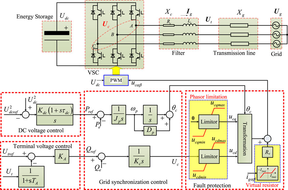
The study proposes a novel voltage source converter (VSC)-based voltage regulatory device based on energy storage and virtual synchronous control, called as the static synchronous condenser (RIVSC). The proposed RIVSC is composed by a VSC, an ES, and a control system, as depicted in Figure 1.
2.1 The VSC Model
Considering both terminal voltage and inner potential, i.e., the output voltage of a three-phase voltage source converter (VSC), the topology of the grid-connected VSC is depicted in Figure 1. The inner potential vector Uc of the VSC and terminal voltage vector Ut can be written as
where Uc and Ut are the magnitudes of the inner potential and terminal voltage. θc and θt are the corresponding phase angles.
In this study, the filter is an inductance. Ignoring the filter’s electromagnetic dynamic, the output current is expressed as
where Is is the VSC’s current. Xc is the filter’s impedance.
The instantaneous active and reactive power (Pe and Qe) of the VSC is calculated by
where utα, utβ, isα, and isβ are the components of instantaneous voltage and current in the αβ reference frame, respectively.
2.2 Grid Integration Control
In the proposed RIVSC, the inner potential is generated by the VSC, which is synchronized with the grid by the active and reactive power controls.
The active power control is responsible for regulating the inner potential’s frequency and phase. The inertial response is featured in the inner potential by a well-known swing equation of SGs, as shown in Figure 1. The energy source comes from the energy storage equipped in the DC-link.
where ωc and θc are the frequency and phase of the inner potential of VSCs, respectively. ωg is the grid frequency. Pref and Pe are reference and instantaneous power of VSCs, respectively. Jp is the virtual inertia coefficient, and Dc is the damping coefficient to enlarge the phase margin of the second-order control loop.
The reactive power control is responsible for regulating the inner potential’s magnitude, as shown in Figure 1. The controller is an integral.
where Uc is the inner potential’s magnitude. Qref and Qe are the reference and instantaneous reactive power of VSCs. Kc is the control coefficient of the reactive power control. With the increase in Kc, the change rate of the inner potential’s magnitude is decreasing under a certain reactive power disturbance.
Under a steady state, the active and reactive power controls regulate the output powers with no error. Under dynamic state, the intrinsic inertial response in active power control is able to provide dynamic support for the grid frequency as Figure 2A. Similarly, due to the integral link in the reactive power control, the magnitude of inner potential maintains the original movement, which can be called as stiffness. Therefore, the voltage difference is spontaneously generated with an additional reactive power output as Figure 2B. The dynamic support of the voltage is spontaneously and passively provided nearly without any time delay and grid condition estimation, which is helpful to improve the dynamics of the grid voltage.
2.3 Energy Storage Configuration and Control
The ES is connected into the DC-link of the VSC, and the VSC is integrated into the grid via a filter.
The stored energy in the DC-link is
where Es is the stored energy, and Udc is the voltage of the DC-link. In this study, the supercapacitor is selected as the energy storage; Cdc is the capacitor of the DC-link. Pin is the input active power. In the RIVSC, the input active power is zero, i.e., Pin = 0, and the energy storage is just required to provide energy support during the inertial response. Under steady state, the RIVSC exchanges with the grid with no active power; thus, the DC-side energy state and voltage is stable.
During the inertial response, the energy state of the RIVSC changes.
where Einertia is the energy change during the inertial response. Prate is the rate active power, and TJ is the equivalent time constant.
The energy state change behaves the DC voltage change. More energy storage will raise less DC voltage deviation. Ideally, more energy storage is better, but the cost should be considered.
The dynamic variant of the DC voltage of the RIVSC should be kept in appropriate scope, i.e.,
where
The maximum DC voltage should consider the tolerance of the Chopper. The DC voltage min should consider the limitation of the PWM.
The Minimum DC voltage Udcmin is
The phase dynamic is related to the active power flow and energy. The DC voltage control is designed as shown in
Figure 1 to regulate the active power reference according to the DC-side voltage deviation for maintaining the state of charge (SOC) of the supercapacitor and DC voltage stable.
where Kdc and τdc are the control gain and time constant.
2.4 AC Voltage Controls
The terminal voltage control aims to maintain the terminal voltage in a certain scope, which is designed as shown in Figure 1 by a proportional control. The terminal voltage control is designed to regulate the reactive power of the proposed RIVSC according to the terminal voltage deviation.
where KAT is the control gain. Ut and Ut∗ fnlowast are the terminal voltage and its reference, respectively.
2.5 Fault Protection Control Procedure
The inertia and stiffness of the RIVSC are beneficial for dynamic active and reactive power support, but the electromagnetic force increases due to the regulation rate of the inner potential decrease under the effect of the inertia and stiffness. With traditional current control, how to limit the fault current of the RIVSC is a very severe problem.
A current limitation method is presented as Figure 1. There are two parts in the current limitation method. This study combines the virtual resistance with a phasor limitation, which are used to reduce the rapid-transient and steady-state fault currents, respectively.
First, a virtual resistor is activated to limit the fault current during transient state when the output current of the RIVSC exceeds the current limit (Qoria et al., 2020).
where Rv and Ilimit are virtual resistor and current limitation. Rset is the value of the virtual resistor. Under normal conditions, the virtual resistor does not work.
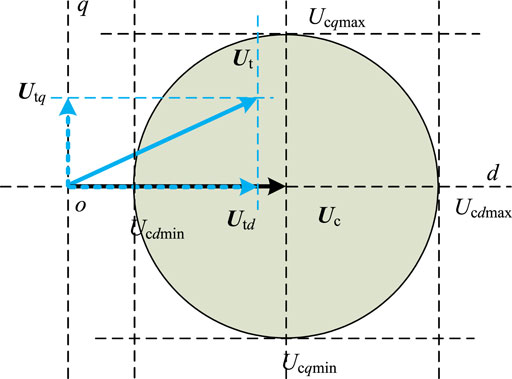
Second, a phasor limitation method is used to restrict the difference between the inner potential of the RIVSC and fault point, as shown in Figure 3.
The fault current of the RIVSC is projected into the inner potential reference coordinate frame as Figure 3.
where Idmax and Iqmax are the dq-axis max current limits.
During the fault operation, the inner potential is limited in the safe zone as in Figure 3.
The dynamic performances of the RIVSC under the grid fault condition are presented in Figure 4.
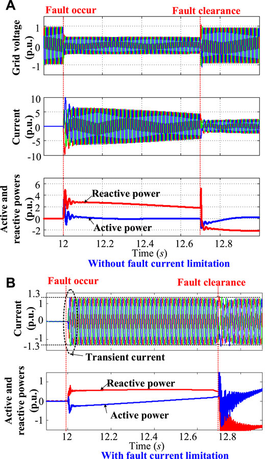
FIGURE 4. Performance of the RIVSC under grid fault condition. (A) Without fault current limitation. (B) With fault current limitation
As shown in Figure 4A, the fault current of the RIVSC rushes to about 10 times rated current without fault current limitation under grid fault, which is unbearable and damages the device. When the fault protection control proposed in this study is enabled, the fault current is less than 1.2 p.u. inside a safe operation range of the power electronic devices, as shown in Figure 4B. Based on the fault protection control, the RIVSC can provide the dynamic reactive power support for grid in a safe operation range, as shown in Figure 4B.
3 Voltage Stiffness Characteristic and Its Influence
3.1 Stiffness Characteristic
The stiffness characteristic means the inner potential’s capability of tolerating the reactive power difference between the actual reactive power and its reference over a time window. The stiffness coefficient Kc determines the stiffness value. With larger stiffness, the changing rate of the inner potential can be reduced under a certain reactive power imbalance condition. As shown in Figure 5A, the deviation rate of the inner potential is reduced with the increase of Kc under a certain reactive power disturbance, but the static deviation still keeps the same.
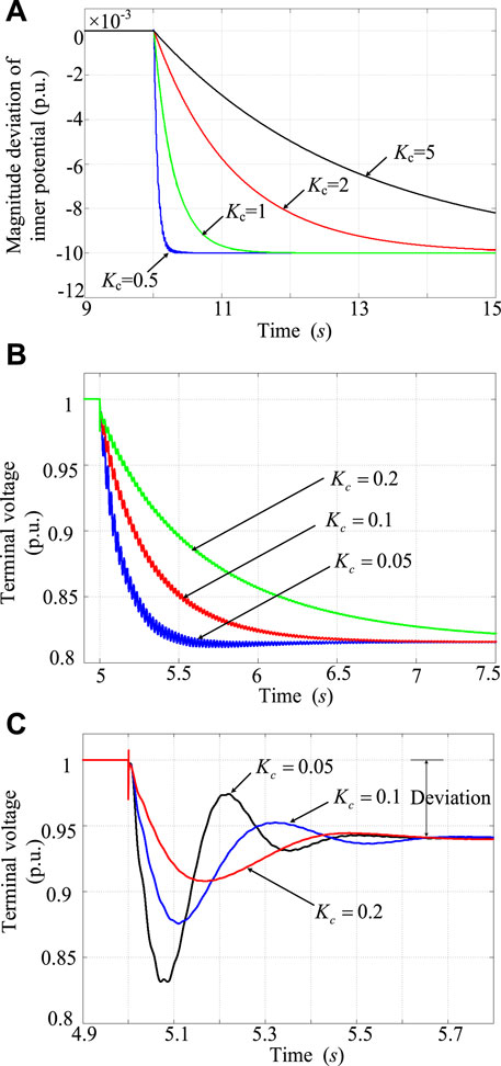
FIGURE 5. Dynamics of the inner potential and the AC voltage at the PCC bus. (A) Magnitude deviation of inner potential (B) without voltage control (C) with voltage control.
With the stiffness increase, the natural reactive power response of the RIVSC is helpful to reduce the change rate of the PCC voltage, as shown in Figure 5B. When the natural reactive power response of the RIVSC stiffness is combined with the normal voltage control, the static deviation of the PCC voltage is not improved, but the nadir is pulled up and enhanced, as shown in Figure 5C. As a result, the stiffness characteristic of the RIVSC and its natural reactive power response are beneficial to improve the voltage dynamics.
3.2 Influence on Grid Voltage Dynamics
This comparison is to highlight the grid voltage stiffness compensation which is quite different from the grid voltage control. The STATCOM is the well-known rapid control device of grid voltage via reactive power compensation and widely used in the bulk power system. Thus, the comparison is made by the STATCOM in this study.
As shown in Figure 6A, the voltage nadir is 0.917 p.u. and 0.957 p.u. with the STATCOM and RIVSC under the same voltage control gain and disturbance, respectively. But the voltage recovery is faster with the STATCOM than with the RIVSC. Figure 6B illustrates the reason of different voltage responses with the STATCOM and RIVSC. First, the STATCOM is equivalent to a controllable current source, and its reactive power slightly declines under disturbance, which will deteriorate the initial voltage deviation. However, the RIVSC provides more and faster reactive power responses under the effect of stiffness after disturbance, which is in favor of reducing the voltage deviation.
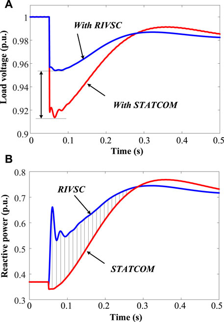
FIGURE 6. Potential application scenario for improving voltage dynamics. (A) Load voltage (B) reactive power.
4 Prototyping Testing
4.1 Experimental System in the Laboratory
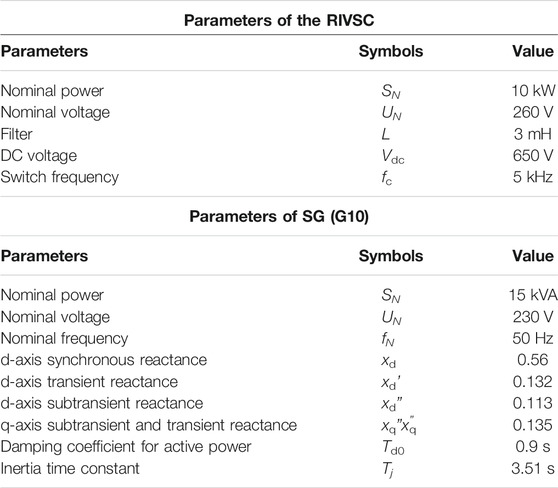
Experimental tests were performed in an experiment power system, as shown in Figure 7. The experiment system is established by a synchronous generator (G10) and a RIVSC. The distributed inductances and capacitors are used to emulate the parameters of the transmission lines (84XL and 85XL), and the resistance and induction motors are regarded as the loads (96LD, 97LD, and 98LD). The primary frequency regulation and auto voltage regulation are equipped in the synchronous generator (G10). In the experiment system, the voltage of the main network is 800V, and T1, T2, T3, T4, and T5 are the variances to couple the facilities into the main network. In addition, the dynamic characteristic of the transmission lines (84XL and 85XL) is equivalent to a 70-km high voltage transmission line with an impedance 12∠85°Ω. The breakers (46QF, 47QF, 48 QF, and 62 QF) are employed to switch on and off transmission lines and loads. The experiment system in physics can reflect more realistic dynamics to obtain more credible results. A power wave recorder is set in the control and dispatching center to collect and record the experimental data of the synchronous generator (G10), transmission network, and loads. The signals of the RIVSC are recorded by YOKOGAWA® ScopeCorders (DL850E). The main parameters are presented in Table A1 in Appendix A1.
4.2 Effects on Grid Voltage Dynamics
In this test, an induction motor in 96LD is launched directly coupled with the grid to emulate the reactive power disturbance. The reactive power characteristic of the inductive motor is presented according to the data of the power wave recorder, as shown in Figure 8A. The consumed reactive power sharply increases to about 6 kvar (inductive) when the induction motor is switched on (0 s). In 0–0.7 s, the consumed reactive power slowly declines and then rapidly decreases at the 0.7 s thereafter. In 0.7–1.0 s, the consumed reactive power rapidly climbs from 4 kvar (inductive) to 1 kvar (capacitive) under this characteristic of reactive power disturbance.
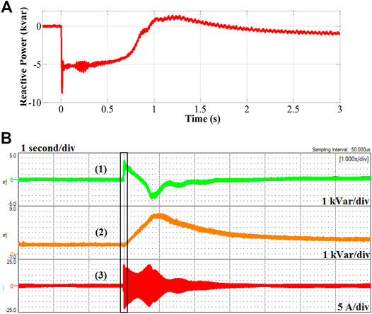
FIGURE 8. Experimental results of the dynamic reactive power response and currents during the reactive power disturbance raised by the launching of the induction motor in 96LD (1s/div). (A) Reactive power characteristics of the induction motor when launched and (B) Dynamic response of the RIVSC and voltage control. (1) Reactive power from the RIVSC (1 kvar/div), (2) Reactive power from the voltage control unit (1 kvar/div), and (3) Phase-a current of the RIVSC (5 A/div).
The dynamic behaviors of the RIVSC and the voltage control are presented in Figure 8B. With the sharp increase of the reactive power consumption when launched, about 4.2 kvar (capacitive) reactive power is provided by the dynamic reactive power response of the RIVSC without any time delays, while the reactive power of the voltage control unit climbs up much more slowly due to the limited control bandwidth and inevitable time delays, as shown in Figure 8B. Moreover, with the rapid decline of the consumed reactive power after launch, the voltage control cannot decline its output reactive power with enough dynamic response and leads to the reactive power surplus due to the limited control bandwidth and time delay, while the natural reactive power response of the RIVSC raised by its stiffness characteristic sharply declines and absorbs more.
Furthermore, Figures 9A,B show the dynamic behavior of the voltage with and without the RIVSC during disturbance of reactive power, respectively. At switching on of the induction motor, the voltage nadir is much higher (280 V) with the RIVSC than the one without the RIVSC (205 V), while the voltage climbs to 425 V without the RIVSC much higher than that with the RIVSC (405 V). Thus, the dynamic reactive power support of the RIVSC is effective to resist the rapid deviation of the voltage.
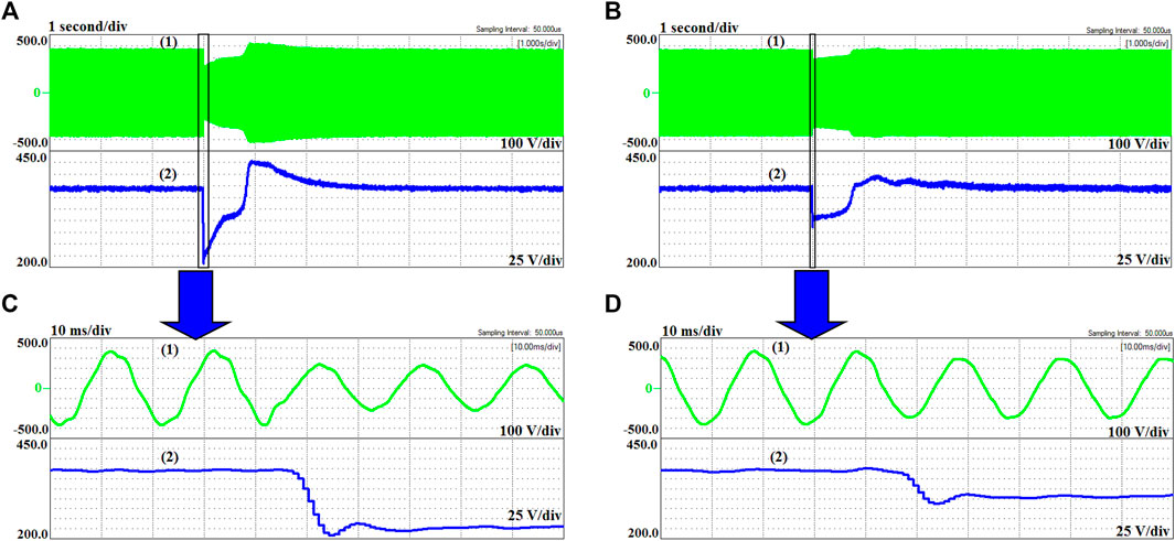
FIGURE 9. Experimental results of the PCC’s voltage during reactive power disturbance raised by the launching of the inductive motor in 96LD (1s/div). (A) Without the RIVSC. (B) With the RIVSC. (C) and (D) are the enlarged windows. (1) PCC’s ac voltage (line-to-line) (100V/div) and (2) PCC’s voltage magnitude (25V/div).
4.3 Fault Ride Through Operation
Figure 10A presents the performance of the RIVSC under grid fault, and Figure 10B is the corresponding zooming window. Grid voltage rapidly declines, and then, the fault current climbs rapidly but is still in the safe zone based on the fault protection control presented in this study. Experimental results illustrate that the fault protection control is effective to reduce the fault current. The case without the fault protection control cannot be implemented because the fault current may damage the facilities.
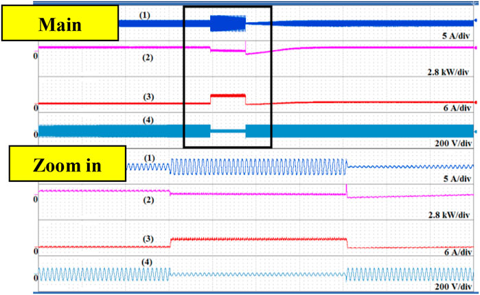
FIGURE 10. Experimental results of the dynamic performance of the RIVSC under grid fault. (1) is the fault current (2) and (3) are active and reactive powers of the RIVSC, (4) is the grid voltage.
5 Application in the Power System
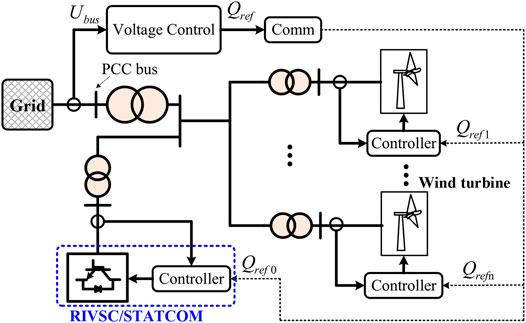
A potential application scenario is established. The RIVSC is combined with the voltage control of the wind farm, as in Figure 11 (Tapia et al., 2007). The voltage control regulates the reactive powers of the RIVSC and wind turbines (Hughes et al., 2005). With a switch off of a reactive load, simulation results of PCC’s voltage are depicted in Figure 12 to illustrate the influence of the RIVSC on the temporary overvoltage. Under the effect of the voltage control without the RIVSC, the PCC’s voltage without the RIVSC jumps over 1.12 p.u. and then gradually falls back. The temporary overvoltage may be raised by the sudden large change of the load flow, which harms the operation security of grid-connected devices. The traditional voltage control cannot immediately reduce the reactive power after disturbance; thus, the overvoltage lasts about 1 s, as shown in Figure 12A, which may trip off some sensitive devices, whereas with the RIVSC, the abundant reactive power is immediately absorbed under the effect of the RIVSC’s stiffness as shown in Figure 12B, which is able to alleviate the temporary overvoltage.
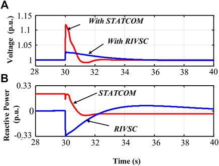
FIGURE 12. Simulated results of PCC’s voltage with and without the RIVSC. (A) PCC’s voltage. (B) Reactive power.
6 Conclusion
This paper presented a novel dynamic compensator called as the static synchronous condenser (RIVSC). The inertia and stiffness characteristics are featured in the RIVSC by the virtual synchronous control for dynamic active and reactive power support for the grid frequency and voltage. Simulation and experiment results validate the feasibility and effectiveness on improving the grid frequency and voltage of the proposed RIVSC. The main contributions of this study can be summarized as follows.
1) The basic principle and control system of the RIVSC is presented by the limited energy storage capacity. The virtual synchronous control is used based on the second-order equation and without the AC current control for better dynamic support capability, and the comprehensive fault current limitation method is proposed to reduce the fault current and keep the RIVSC operating in a safe zone.
2) The inertia and stiffness characteristics are featured in the proposed RIVSC by the virtual synchronous control, and the RIVSC can naturally provide the dynamic active and reactive powers to support the grid frequency and voltage with a better dynamic response than traditional inertia control based on the df/dt-method and voltage control.
3) The stiffness compensation of the RIVSC is first proposed and can be used as the supplement to the traditional voltage control to improve grid voltage dynamics, which is a potential application to alleviate the temporary overvoltage. It is validated that the RIVSC is effective to alleviate the temporary overvoltage.
4) The prototype of the RIVSC is set up, and the improving frequency and voltage dynamics are validated by the physical experiment systems with the more realistic dynamics.
In the future research, the topology for large capacity, control, and application of the proposed RIVSC requires deep study. The RIVSC is potential to replace the conventional STATCOM and synchronous condenser. There are some application scenarios, e.g., located at the sending terminal of the HVDC to alleviate the transient overvoltage, located at the distributed to reduce the voltage flicker to improve the power quality.
Data Availability Statement
The original contributions presented in the study are included in the article/supplementary material; further inquiries can be directed to the corresponding author.
Author Contributions
XD proposed the idea of the experiment. LS proposed the idea of voltage resilience and experimental devices.
Funding
The work is supported by the National Natural Science Funds of China (Grant No. 52007135).
Conflict of Interest
Author YT was employed by the company State Grid Liaoning Electric Power Supply Company. Author JL was employed by the company State Grid Jilin Electric Power Supply Company.
The remaining authors declare that the research was conducted in the absence of any commercial or financial relationships that could be construed as a potential conflict of interest.
Publisher’s Note
All claims expressed in this article are solely those of the authors and do not necessarily represent those of their affiliated organizations, or those of the publisher, the editors, and the reviewers. Any product that may be evaluated in this article, or claim that may be made by its manufacturer, is not guaranteed or endorsed by the publisher.
Appendix
References
Cao, Y., Wang, W., Li, Y., Tan, Y., Chen, C., He, L., et al. (2018). A Virtual Synchronous Generator Control Strategy for VSC-MTDC Systems. IEEE Trans. Energ. Convers. 33 (2), 750–761. doi:10.1109/tec.2017.2780920
Du, E., Zhang, N., Hodge, B.-M., Wang, Q., Lu, Z., Kang, C., et al. (2019). Operation of a High Renewable Penetrated Power System with CSP Plants: A Look-Ahead Stochastic Unit Commitment Model. IEEE Trans. Power Syst. 34 (1), 140–151. doi:10.1109/tpwrs.2018.2866486
Hou, X., Sun, Y., Han, H., Liu, Z., Su, M., Wang, B., et al. (2018). A General Decentralized Control Scheme for Medium-/High-Voltage Cascaded STATCOM. IEEE Trans. Power Syst. 33 (6), 7296–7300. doi:10.1109/tpwrs.2018.2865127
Huang, S-H., Schmall, J., Conto, J., Adams, J., Chang, Y., and Carter, C. (2012). “Voltage Control Challenges on Weak Grids with High Penetration of Wind Generation: ERCOT Experience,” in Proc. IEEE Power Energy Soc. General Meeting, San Diego, CA, USA, 22-26 July 2012 (IEEE), 1–7.
Hughes, F. M., Anaya-Lara, O., Jenkins, N., and Strbac, G. (2005). Control of DFIG-Based Wind Generation for Power Network Support. IEEE Trans. Power Syst. 20 (4), 1958–1966. doi:10.1109/tpwrs.2005.857275
Lee, G.-S., Kwon, D.-H., Moon, S.-I., and Hwang, P.-I. (2020). Reactive Power Control Method for the LCC Rectifier Side of a Hybrid HVDC System Exploiting DC Voltage Adjustment and Switched Shunt Device Control. IEEE Trans. Power Deliv. 35 (3), 1575–1587. doi:10.1109/tpwrd.2019.2949906
Liu, B., Li, Z., Chen, X., Huang, Y., and Liu, X. (2018). Recognition and Vulnerability Analysis of Key Nodes in Power Grid Based on Complex Network Centrality. IEEE Trans. Circuits Syst. 65 (3), 346–350. doi:10.1109/tcsii.2017.2705482
Liu, B., Li, Z., Dong, X., Yu, S. S., Chen, X., Oo, A. M. T., et al. (2021). Impedance Modeling and Controllers Shaping Effect Analysis of PMSG Wind Turbines. IEEE J. Emerg. Sel. Top. Power Electron. 9 (2), 1465–1478. doi:10.1109/jestpe.2020.3014412
Mendis, N., Muttaqi, K. M., and Perera, S. (2014). Management of Battery-Supercapacitor Hybrid Energy Storage and Synchronous Condenser for Isolated Operation of PMSG Based Variable-Speed Wind Turbine Generating Systems. IEEE Trans. Smart Grid 5 (2), 944–953. doi:10.1109/tsg.2013.2287874
Qoria, T., Gruson, F., Colas, F., Denis, G., Prevost, T., and Guillaud, X. (2020). Critical Clearing Time Determination and Enhancement of Grid-Forming Converters Embedding Virtual Impedance as Current Limitation Algorithm. IEEE J. Emerg. Sel. Top. Power Electron. 8 (2), 1050–1061. doi:10.1109/jestpe.2019.2959085
Ramos, A. J. P., and Tyll, H. (1989). Dynamic Performance of a Radial Weak Power System with Multiple Static VAR Compensators. IEEE Trans. Power Syst. 4 (4), 1316–1325. doi:10.1109/59.41681
Shang, L., Dong, X., Liu, C., and Gong, Z. (2021). Fast Regulation Control for Grid Frequency and Voltage Based on the Amplitude-Phase-Locked-Loop. IEEE Trans. Smart Grid, Early Access, 1. doi:10.1109/TSG.2021.3133580
Shang, L., Dong, X., Liu, C., and He, W. (2021). Modelling and Analysis of Electromagnetic Time Scale Voltage Variation Affected by Power Electronic Interfaced Voltage Regulatory Devices. IEEE Trans. Power Syst., 1. doi:10.1109/TPWRS.2021.3100606
Shang, L. (2019). “Rotational-inertia-and-voltage-stiffness Compensator to Improve Grid Voltage Dynamic,” in Proceedings of IEEE Sustainable Power and Energy Conference, Beijing, China, 21-23 Nov. 2019 (iSPEC).
Tapia, G., Tapia, A., and Ostolaza, J. X. (2007). Proportional-Integral Regulator-Based Approach to Wind Farm Reactive Power Management for Secondary Voltage Control. IEEE Trans. Energ. Convers. 22 (2), 488–498. doi:10.1109/tec.2005.858058
Teleke, S., Abdulahovic, T., Thiringer, T., and Svensson, J. (2008). Dynamic Performance Comparison of Synchronous Condenser and SVC. IEEE Trans. Power Deliv. 23 (3), 1606–1612. doi:10.1109/tpwrd.2007.916109
Varma, R. K., and Mohan, S. (2020). Mitigation of Fault Induced Delayed Voltage Recovery (FIDVR) by PV-STATCOM. IEEE Trans. Power Syst. 35 (6), 4251–4262. doi:10.1109/tpwrs.2020.2991447
Wang, S., Hu, J., and Yuan, X. (2015). Virtual Synchronous Control for Grid-Connected DFIG-Based Wind Turbines. IEEE J. Emerg. Sel. Top. Power Electron. 3 (4), 932–944. doi:10.1109/jestpe.2015.2418200
Xiong, L., Liu, X., Liu, Y., and Zhuo, F. (2020). Modeling and Stability Issues of Voltage-Source Converter Dominated Power Systems: a Review. Csee Jpes. early access. doi:10.17775/CSEEJPES.2020.03590
Xue, Y., and Zhang, X.-P. (2017). Reactive Power and AC Voltage Control of LCC HVDC System with Controllable Capacitors. IEEE Trans. Power Syst. 32 (1), 753–764. doi:10.1109/tpwrs.2016.2557342
Zhang, L. (2010).Modeling and Control of VSC-HVDC Links Connected to Weak Ac Systems. Ph.D. dissertation, School of Electrical Engineering. Stockholm, Sweden: KTH University.
Zhao, M., Yuan, X., Hu, J., and Yan, Y. (2016). Voltage Dynamics of Current Control Time-Scale in a VSC-Connected Weak Grid. IEEE Trans. Power Syst. 31 (4), 2925–2937. doi:10.1109/tpwrs.2015.2482605
Keywords: voltage stiffness, rotating inertia and voltage stiffness compensator (RIVSC), voltage dynamic, voltage regulation, overvoltage
Citation: Shang L, Han C, Dong X, Tian Y and Liu J (2022) Voltage Source Converter–Based Voltage Stiffness Compensator to Improve Grid Voltage Dynamics. Front. Energy Res. 10:835066. doi: 10.3389/fenrg.2022.835066
Received: 14 December 2021; Accepted: 03 January 2022;
Published: 02 February 2022.
Edited by:
Liansong Xiong, Nanjing Institute of Technology (NJIT), ChinaReviewed by:
Yuanzhu Chang, Polytechnique Montréal, CanadaXinshou Tian, North China Electric Power University, China
Ning Li, Xi’an University of Technology, China
Copyright © 2022 Shang, Han, Dong, Tian and Liu. This is an open-access article distributed under the terms of the Creative Commons Attribution License (CC BY). The use, distribution or reproduction in other forums is permitted, provided the original author(s) and the copyright owner(s) are credited and that the original publication in this journal is cited, in accordance with accepted academic practice. No use, distribution or reproduction is permitted which does not comply with these terms.
*Correspondence: Lei Shang, c2hhbmdsZWlAd2h1LmVkdS5jbg==
 Lei Shang
 Chunyi Han1