 Feng Xu
 Qingyang Ren
 Hao Ling3*
95% of researchers rate our articles as excellent or good
Learn more about the work of our research integrity team to safeguard the quality of each article we publish.
Find out more
ORIGINAL RESEARCH article
Front. Energy Res. , 08 April 2022
Sec. Carbon Capture, Utilization and Storage
Volume 10 - 2022 | https://doi.org/10.3389/fenrg.2022.833388
This article is part of the Research Topic CO2-Enhanced Shale Gas Recovery: Mechanisms and Coupling Behaviors View all 5 articles
The sealing problem of the cement sheath often appears in gas wells for underground energy exploitation, especially when horizontal multistage fracturing technology is used in the shale gas industry. In this article, according to the elastic–plastic mechanics and Mohr–Coulomb yield criteria, an analytical solution of the equations is obtained by considering the effect of pressure on the fluid column, volume shrinkage, or expansion and geological characteristics on the initial stress of the cement sheath. The analysis of the example indicates that the smaller the initial stress of the cement sheath, the lower its radial stress and circumferential stress, which is under the maximum inner casing pressure of 150 MPa. With the increase of initial stress of the cement sheath, it is easier for the first and second interfaces to enter the plastic and damage state for the cement sheath. The smaller the initial stress of the cement sheath, the earlier the damage appears, and it develops with the increase of inner casing pressure more quickly. When the initial stress of the cement sheath is less than 7.9 MPa, the damage factor finally reaches 1 with the increase of internal casing pressure; however, when the initial stress of the cement sheath is greater than 34.2 MPa, the damage factor always remains 0 with the increase of inner casing pressure. The results preliminarily revealed that the initial stress of the cement sheath plays a decisive role in promoting its integrity and may provide guidance for the choice of the formula of cement and construction methods in the oil field.
Energy is the cornerstone of human survival and human social development. Global unconventional oil and gas resources account for 80% of oil and gas resources and will become the main energy in the future (Xu et al., 2022). Cement slurry cementing is widely used in underground energy exploitation. Due to the influence of cement characteristics, formation pressure, temperature, and post-fracturing construction operations, the seal integrity of the cement sheath meets a serious challenge, which causes the plastic ring of the cement sheath yield; the first and second interface micro-seam joints and the annulus pressure are extremely prominent (Wang et al., 2013).
In the process of multistage fracturing of horizontal wells, the cement sheath is constantly affected by the cyclic alternation of low temperature (fracturing fluid) and high temperature (formation), which could cause shear, tensile, and interface separation damage easily, resulting in shale gas entering into the cement sheath fracture and generating annular pressure problems (Saint-Marc, 2008), as shown in Figures 1, 2. The first or second interface separation indicates bond failure at the inner/outer boundary of the cement sheaths for the plastic deformation of the cement sheath cannot be restored to the initial state under circulating pressure in casing, which results in discontinuous displacement of casing–cement sheath-formation. The shear damage indicates the shear stress of the cement sheath that exceeds the friction stress in the Mohr–Coulomb criterion. The tensile failure indicates that the tensile stress exceeds tensile strength. Therefore, it is essential to investigate the stress distribution of the casing–cement sheath-formation system during construction in cementing operations.
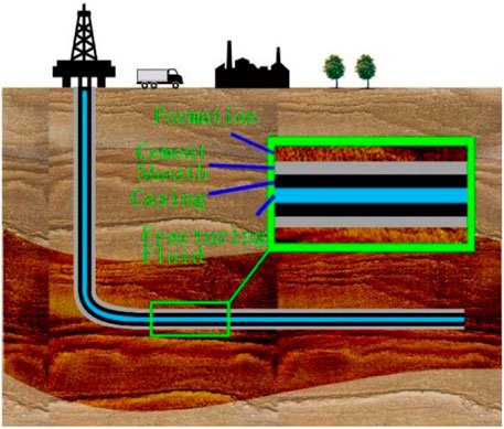
FIGURE 1. Diagram of a well in energy exploitation and storage.
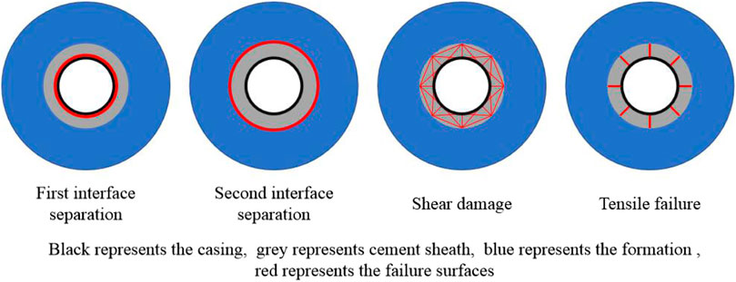
FIGURE 2. Failure types of the cement sheath.
Domestic and foreign scholars have performed a lot of research on the integrity of cement sheath seals (Liu et al., 2020; Chen et al., 2021). Zhang et al. (2017) studied the sealing characteristics of the cement sheath in the fracturing process by simulation experiments and found that with the increase of the number of fracturing alternating stress, the plasticity deformation continues to accumulate and eventually produces microcracks; Fang et al. (1995) and Yin et al. (2006) gave the elastic analytical solution of casing–cement sheath-formation under nonuniform ground stress under ideal conditions; Li et al. (2005a) analyzed the elastoplastic theory of casing, cement sheath, and shaft wall rock and gave the elastoplastic analytical solution. Deng et al. (1994) deduced the formula for calculating the stress state of the casing and cement sheath under the creep load of various nonuniform surrounding rocks; Jing et al. (2009) deduced the theoretical calculation formulas of thermal stress and thermal displacement of the casing–cement sheath-formation coupling system based on the theory of elastic mechanics and thermodynamics and analyzed the system heat, the radial distribution of stress, and thermal displacement; Xu et al. (2015) coupled the thermal stress and elastoplastic mechanics to give the analytical solution and numerical solution of the stress and deformation of the casing–cement sheath-formation system; Li et al. (2010) calculated the stress of the cement sheath and its deformation characteristics under high temperature and nonuniform stress conditions. Li et al. (2005b) carried out a theoretical calculation method to investigate the influence of the cement sheath elastic modulus on the stress state of the composite; Zhang et al. (2013) studied the impact of the elastic parameters of the cement sheath on the structural integrity of casing–cement sheath-formation by ANSYS software.
However, all of the aforementioned studies have applied the far-field stress directly to the casing–cement sheath-formation combination, neglecting the stress release of the wellbore after drilling and the entire process of stress application. Based on this, to study the mechanical characteristics of the whole process of cement solidification, the author defines the stress state of the cement sheath formed by solidification of the cement slurry in this article as the initial stress of the cement sheath, and at this moment, it receives equal radial and circumferential stress at each point. The cementing cement sheath-forming process includes the stress release of the wellbore after drilling, the cement slurry pressure causes the wellbore and the casing to deform coordinately, and the cement slurry solidification shrinkage or expansion, and the initial stress of the cement sheath is subjected to the liquid column pressure during the solidification process, volume shrinkage or expansion, formation characteristics, and other factors. In order to investigate the influence of different initial stresses on the mechanical characteristics of the casing–cement sheath-formation system after solidification of cement slurry, the mechanical model of the casing–cement sheath-formation system considering the initial stress state of the cement sheath is established by using the elastoplastic theory.
The cement sheath often exceeds hundreds of meters in the axial direction, and it is restricted deformation in the axial direction. The model of casing–cement sheath-formation can be simplified to the plane strain model. Before conducting research, the following assumptions need to be made on the model:
(1) During the study, it is assumed that the casing and formation are elastic materials because the formation stress does not exceed the yield stress of the casing and rock (Xu et al., 2017).
(2) During the study, it is assumed that the cement sheath is an ideal elastic–plastic material and meets the Mohr–Coulomb criterion (Xu et al., 2021).
(3) The initial stress formed by cement solidification is equal everywhere, that is, the first and second interface contact stresses are equal, and the specific parameters are shown in Figure 3;
(4) The casing is completely centered, that is, the casing and the cement sheath are concentric rings, and the cement is completely filled; this article adopts the elastic mechanical symbol convention, positive tensile stress, and negative compressive stress.
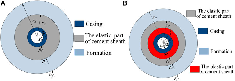
FIGURE 3. Casing–cement sheath-formation system model. (A) Assembly model after the cement setting. (B) Assembly model in hydraulic fracturing.
Figure 3A shows the physical size and stress state of the casing–cement sheath-formation system model after solidification and coordinated deformation of cement. Figure 3B shows the physical model and mechanical parameters of the composite during fracturing, that is, the physical model of Figure 3B is due to Figure 3A. The physical model is caused by the application of internal pressure in the casing. In the figure,
For cement sheaths with planar problems, the failure criterion is generally based on the Mohr–Coulomb yield criterion. Because the first and second interfacial stresses are equal after the cement stone solidifies, the calculated cement sheath satisfies
As shown in Figure 3, when the pressure
When Eqs 1, 2 are jointly solved and the boundary condition
where
When the cement sheath
The stress component of the elastic zone of the cement sheath (
When the elastic zone
The casing–cement sheath-formation system has continuity at the first and second interface displacements, since the stress state in Figure 3 is formed by the stress state of the (1) stress state and the internal pressure of the casing during the fracturing stage, and the casing is formed. The change in the displacement of the cement sheath-formation system is due to the application of the internal pressure of the casing, so the displacement should be the displacement change caused by the internal pressure of the casing. The actual displacement generated by the elastic zone fracturing process shall be the change of the displacement of the composite during the fracturing process subtracted by the displacement change of the composite during the solidification process of the cement stone:
According to the Lame formula (Jin and Chen, 2012), the radial displacement expressions of the casing, cement sheath, and borehole elastic region are as follows:
The displacement of the outer wall for the casing is:
The displacement of borehole wall is:
The displacement of the cement sheath elastic zone is:
where
In the plastic zone of the cement sheath, considering the condition of the plane strain model
Using Eq. 11, the aforementioned formula can be written as:
Through the integral formula (Eq. 12), the expression of the cement sheath plastic region
Considering the continuity of the first interface in the casing–cement sheath-formation system, the elastoplastic interface of the cement sheath, and the displacement at the second interface caused by the increase in the internal pressure of the casing, the relationship between the elastic–plastic interface stress of the cement sheath and the first and second interface stresses and by combining the formulas of Eqs 4, 6, 8–10, 13, the system of stress characteristic equations of the system assembly can be obtained.
Eq. 14 is a five-element equation for the unknown parameters
According to the current situation of the southwest shale gas well and the possible stress state in the future deep mining process, the physical and mechanical parameters of the casing–cement sheath-stratum combination are selected as shown in Table 1. The maximum site stress

TABLE 1. Physical and mechanical parameters of the casing–cement sheath- formation model.
The relationship between the elastoplastic interface radius and the casing internal pressure under different initial stress conditions of the cement sheath is shown in Figure 4. It can be found from the figure that the smaller the initial stress of the cement sheath, the easier it is to enter the plastic state, and as the internal pressure of the casing increases, the elastoplastic interface gradually expands outward from the first interface, and finally the entire cement sheath enters the plasticity. At the first interface, the initial stress of the cement sheath is increased from 0 to 50 MPa, and the internal pressure of the casing entering the plastic condition is increased from 33.89 to 203.46 MPa; also, at the second interface, the bottom hole pressure entering the plastic state is higher. When the initial stress of the cement sheath increases from 0 to 50 MPa, the internal pressure of the casing increases from 203.46 to 504.18 MPa.
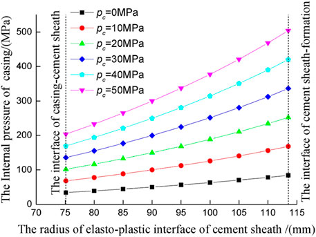
FIGURE 4. Relationship between the elastoplastic interface and casing pressure.
Figures 5, 6, respectively, show the radial and circumferential stress distribution of the cement sheath when the initial stress of different cement sheaths is 150 MPa inside the casing. When the local stress and the casing internal pressure are directly applied to the combination, the radial compressive stress of the cement sheath is between −102.6 MPa and −82.8 MPa, and the radial stress is greater than the initial stress of the cement sheath from 0 to 50 MPa; the stress is directly applied to the assembly. The circumferential stress is similar to the radial stress at 40–50 MPa. Regardless of whether the cement sheath is in an elastic or plastic state, the radial compressive stress decreases as the radius of the cement sheath increases.
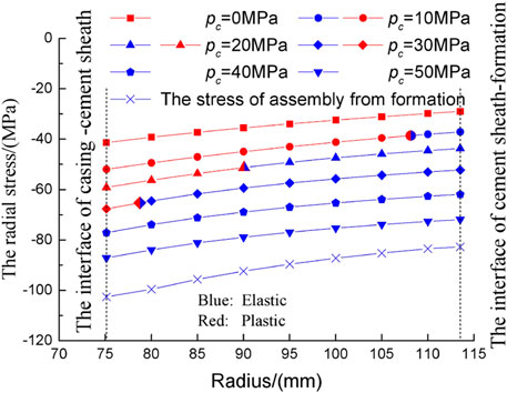
FIGURE 5. Radial stress distribution of the cement sheath on a casing pressure of 150 MPa.
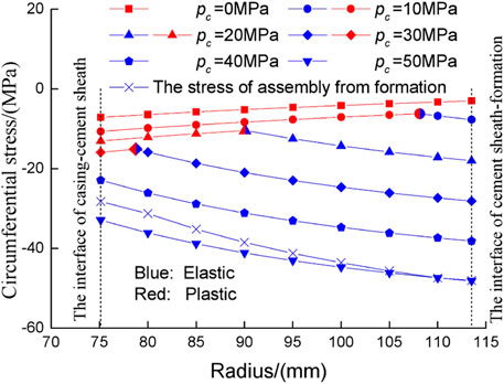
FIGURE 6. Circumferential stress distribution of the cement sheath on a casing pressure of 150 MPa.
When the initial stress is 0–50 MPa, the initial stress of the cement sheath is larger, and the radial stress is larger; the radial compressive stress is the largest at the first interface and is from -87.16 MPa to −41.37 MPa, and at the second interface, the stress is the smallest one, which is from −71.92 MPa to −29.02 MPa. For the circumferential stress, the variation law is directly related to the elastoplastic characteristics. It shows that as the radius of the cement sheath increases, the circumferential compressive stress of the plastic zone decreases, and the circumferential compressive stress of the elastic zone increases, mainly in three cases: 1) the cement sheath is in a fully plastic state. For example, the initial stress of the cement sheath is 0 MPa, the circumferential stress decreases with the radius of the cement sheath, and the maximum circumferential stress appears at the first interface, which is −7.13 Mpa; the minimum circumferential stress appears at the second interface, which is −3.01 MPa; 2) the inner side of the cement sheath is in a plastic state and the outer side is in an elastic state, i.e., the initial stress of the cement sheath is 10 MPa, 20 MPa, and 30 MPa, the circumferential compressive stress first decreases and then increases. The circumferential stress is the smallest at the elastoplastic interface, and the maximum circumferential stress is at the first or second interface, depending on the specific situation; (3) the cement sheath is in a fully elastic state, i.e., the initial stress of the cement sheath is 40 and 50 MPa, the circumferential stress increases with the radius of the cement sheath, and the minimum one appears at the first interface, which is from −22.90 MPa to −32.90 MPa; the maximum one appears at the second interface, which is from −38.15 MPa to −48.15 MPa.
During the fracturing construction process, as the internal pressure of the casing increases, the cement sheath in the elastic state gradually undergoes yield failure from the first interface, entering the plasticity. Then, the plastic volume gradually increases, and even the entire cement sheath finally enters the plastic state. In this article, the damage factor
Damage factor:
As shown in Figure 7,
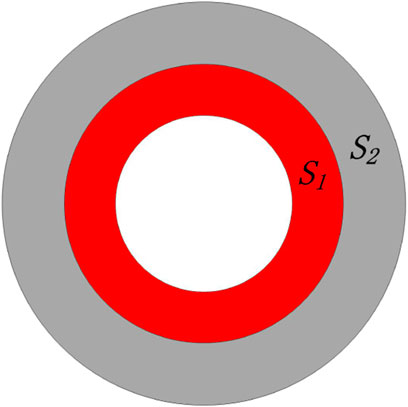
FIGURE 7. Schematic diagram of the elastoplastic zone of the cement sheath.
The damage results of the internal pressure of the casing under different initial stress conditions are calculated. As shown in Figure 8, the initial stress of the cement sheath has a significant influence on the evolution process of the damage factor during the internal pressure loading process. As the initial stress of the cement sheath increases, the damage appears later or even does not occur, and the rate of damage increases with the increase of internal pressure. When the initial stress is 0 MPa, the cement sheath is damaged when the internal pressure of the casing is 33.89 MPa. When it is only 83.99 MPa, the cement sheath damage factor reaches 1, indicating that the whole enters the plastic state. When the initial stress is 10, 20, and 30 MPa, the corresponding casing internal pressure is 67.81, 101.72, and 135.63 MPa, respectively. When the internal pressure reaching the maximum downhole casing pressure of the oil and gas well is 150 MPa, the damage factors are 0.84 0.34, and 0.08 and did not enter the plastic state as a whole. When the initial stress is above 40 MPa, even if the internal pressure reaches the maximum casing internal pressure of 150 MPa, the cement sheath can still maintain the damage factor of 0, that is, the cement sheath as a whole is in an elastic state.
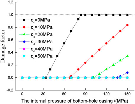
FIGURE 8. Relationship between the damage factor of the cement sheath and casing pressure.
In this article, considering the volume shrinkage, constant, and expansion of the cement slurry during the solidification process, assuming the initial stress state of the cement sheath is 0–50 MPa, a casing–cement sheath-shale formation model is established; the stress state of the cement sheath and the damage characteristics of the cement sheath during the fracturing process are deduced by the Mohr–Coulomb yield criterion. The conclusions are as follows:
(1) When the initial stress of the cement sheath is smaller, the radial stress and the circumferential stress are smaller, and the smaller the internal pressure of the casing causing the cement sheath to enter the plastic state, the more likely the damage occurs in the cement sheath.
(2) The damage factor is introduced. According to the example analysis, the smaller the initial stress of the cement sheath, the earlier the damage occurs, and the damage factor grows faster. When the initial stress of the cement sheath is less than 7.9 MPa, the damage factor
The original contributions presented in the study are included in the article/Supplementary Material, further inquiries can be directed to the corresponding authors.
FX: methodology, investigation, and writing–original draft. ZL: data collection and writing–original draft. QR: writing–review and editing. XZ and GY: supervision and validation. HL and HY: data collection. HW seriously participated in the research group Shu Yan, fitted and analyzed the collected data, and prepared for writing the paper.
Authors FX, ZL, and GY were employed by the company China Merchants Chongqing Communications Research & Design Institute Co., Ltd. Author HY was employed by the company Guangzhou Expressway Co., Ltd.
The remaining authors declare that the research was conducted in the absence of any commercial or financial relationships that could be construed as a potential conflict of interest.
All claims expressed in this article are solely those of the authors and do not necessarily represent those of their affiliated organizations, or those of the publisher, the editors and the reviewers. Any product that may be evaluated in this article, or claim that may be made by its manufacturer, is not guaranteed or endorsed by the publisher.
The authors would like to acknowledge the financial support of the National Key Research and Development Program of China (2018YFC1504903), the Key Projects of Chongqing Science and Technology Bureau (cstc2019jscx-gksbX0071 and cstc2019jscx-gksbX0072), and the Science and Technology Project of Jiangxi Provincial Department of Transportation (2020H0026 and 2020H0052).
Chen, Y., Yin, T., and Li, X. (2021). Experimental Investigation on Dynamic Mechanical Behavior and Fracture Evolution of Fissure-Filled Red sandstone after thermal Treatment. Eng. Geology. 295, 106433. doi:10.1016/j.enggeo.2021.106433
Chu, W., and Yang, Y. (2015). Calculation of Micro-annulus Size in Casing-Cement Sheath-Formation System under Continuous Internal Casing Pressure Change. Pet. Exploration Development 42 (3), 379–385. doi:10.1016/s1876-3804(15)30033-1
Deng, J., Wang, K., and Huang, R. (1994). Collapse Resistance O Foil Well Casing-Cement Mantle Combinatiton Subjected to Non-uniform Loading by Rock Creep. Chin. J. Rock Mech. Eng. 13 (2), 160–167. doi:10.1007/BF02657007
Fang, J., Zhao, H., and Yue, B. (1995). Analysis of Loading Property of Casing and Cement Sheath under Nonuniform Geologic Stress. J. China Univ. Pet. 19 (6), 52–57.
Jackson, P. B., and Murphey, C. E. (1993). Effect of Casing Pressure on Gas Flow through a Sheath of Set Cement. Amsterdam, Netherlands: SPE 25698-MS. doi:10.2523/25698-MS
Jing, L., Lin, C., and Yang, S. (2009). Theoretical Solution of thermal Stress for Cement Formation Coupling System. J. China Univ. Pet. 33 (2), 63–69. doi:10.3321/j.issn:1673-5005.2009.02.012
Li, J., Chen, M., and Liu, G. (2005a). Elastic-plastic Analysis of Casing-concrete Sheath-Rock Combination. Acta Petrolei Sinica 26 (6), 99–103. doi:10.1016/j.molcatb.2005.02.001
Li, J., Chen, M., and Zhang, H. (2005b). Effects of Cement Sheath Elastic Modulus on Casing External Collapse Load. J. China Univ. Pet. 29 (6), 41–44. doi:10.3321/j.issn:1000-5870.2005.06.010
Li, Y., Liu, S., and Wang, Z. (2010). Analysis of Cement Sheath Coupling Effects of Temperature and Pressure in Non-uniform In-Situ Stress Field. SPE, 131878. doi:10.2118/131878-ms
Liu, R., He, Y., Zhao, Y., Jiang, X., and Ren, S. (2020). Tunnel Construction Ventilation Frequency-Control Based on Radial Basis Function Neural Network. Automation in Construction 118, 103293. doi:10.1016/j.autcon.2020.103293
Saint-Marc, J. (2008). “Initial State of Stress: the Key to Achieving Long-Term Cement-Sheath Integrity,” in SPE Annual Technical Conference and Exhibition, Society of Petroleum Engineers. doi:10.2118/116651-ms
Wang, B., Yan, X., and Yang, X. (2013). Study on Leakage Rate of Natural Gas through an Abandoned Well in Depleted Natural Gas Reservoir Based on SCP. Sci. Technology Eng. 13 (26), 7749–7753. doi:10.3969/j.issn.1671-1815.2013.26.028
Xu, F., Tang, S., and Ren, Q. (2021). Experimental Study on the thermal Damage Characteristics of Cement Stone. Therm. Sci. 25, 3327–3335. doi:10.2298/tsci200618317x
Xu, F., Yang, C., and Guo, Y. (2017). Effect of Bedding Planes on Wave Velocity and AE Characteristics of the Longmaxi Shale in China. Arabian J. Geosciences 10 (6), 141–150. doi:10.1007/s12517-017-2943-y
Xu, F., Xu, Z., Tang, S., Ren, Q., Guo, Y., Wang, L., et al. (2022). Evolution of Physical and Mechanical Properties of Cementing Materials during Underground Energy Exploitation and Storage. J. Energ. Storage 45, 103775. doi:10.1016/j.est.2021.103775
Xu, H., Zhang, Z., and Shi, T. (2015). Influence of the WHCP on Cement Sheath Stress and Integrity in HTHP Gas Well. J. Pet. Sci. Eng. 126, 174–180. doi:10.1016/j.petrol.2014.11.028
Yin, Y., Cai, Y., and Chen, Z. (2006). Theoretical Solution of Casing Loading in Non-uniform Ground Stress Field. Chin. J. Theor. Appl. Mech. 38 (6), 835–842. doi:10.7623/syxb200604031
Zhang, J., Zhang, D., and Zhang, Q. (2013). Impact of Elastic Parameters of Cement Ring on Structural Integrity of Casing-Cement Ring-Strata Cementing Combination. Oil Drilling Prod. Technology 35 (5), 43–46. doi:10.3969/j.issn.1000-7393.2013.05.012
Zhang, L., Liu, R., and Zhou, S. (2017). Investigation on Sealing Failure and Improving of Cement Sheath under Simulated Staged Fracturing. Sci. Technology Eng. 17 (13). doi:10.3969/j.issn.1671-1815.2017.13.031
Keywords: cement sheath integrity, initial stress, Mohr–Coulomb yield criteria, theoretical solution, damage factor, shale gas
Citation: Xu F, Ren Q, Ling H, Yin H, Zhou X, Liu Z and Yang G (2022) Analysis of Stress State and Damage Characteristics of the Cement Sheath. Front. Energy Res. 10:833388. doi: 10.3389/fenrg.2022.833388
Received: 11 December 2021; Accepted: 21 February 2022;
Published: 08 April 2022.
Edited by:
Guowen Xu, Colorado School of Mines, United StatesReviewed by:
Hongyu Gu, Chengdu Geological Survey Center, ChinaCopyright © 2022 Xu, Ren, Ling, Yin, Zhou, Liu and Yang. This is an open-access article distributed under the terms of the Creative Commons Attribution License (CC BY). The use, distribution or reproduction in other forums is permitted, provided the original author(s) and the copyright owner(s) are credited and that the original publication in this journal is cited, in accordance with accepted academic practice. No use, distribution or reproduction is permitted which does not comply with these terms.
*Correspondence: Feng Xu, c2N4dWZlbmdAMTYzLmNvbQ==; Qingyang Ren, cXlyZW5AY3FqdHUuZWR1LmM=; Hao Ling, Mjc2NDg2ODcxQHFxLmNvbQ==
Disclaimer: All claims expressed in this article are solely those of the authors and do not necessarily represent those of their affiliated organizations, or those of the publisher, the editors and the reviewers. Any product that may be evaluated in this article or claim that may be made by its manufacturer is not guaranteed or endorsed by the publisher.
Research integrity at Frontiers
Learn more about the work of our research integrity team to safeguard the quality of each article we publish.